Publisher’s version / Version de l'éditeur:
Canadian Journal of Civil Engineering, 26, 2, pp. 156-167, 1999-04-01
READ THESE TERMS AND CONDITIONS CAREFULLY BEFORE USING THIS WEBSITE. https://nrc-publications.canada.ca/eng/copyright
Vous avez des questions? Nous pouvons vous aider. Pour communiquer directement avec un auteur, consultez la première page de la revue dans laquelle son article a été publié afin de trouver ses coordonnées. Si vous n’arrivez pas à les repérer, communiquez avec nous à [email protected].
Questions? Contact the NRC Publications Archive team at
[email protected]. If you wish to email the authors directly, please see the first page of the publication for their contact information.
NRC Publications Archive
Archives des publications du CNRC
This publication could be one of several versions: author’s original, accepted manuscript or the publisher’s version. / La version de cette publication peut être l’une des suivantes : la version prépublication de l’auteur, la version acceptée du manuscrit ou la version de l’éditeur.
For the publisher’s version, please access the DOI link below./ Pour consulter la version de l’éditeur, utilisez le lien DOI ci-dessous.
https://doi.org/10.1139/cjce-26-2-156
Access and use of this website and the material on it are subject to the Terms and Conditions set forth at
Behaviour of steel frames under fire conditions
Nwosu, D. I.; Kodur, V. K. R.
https://publications-cnrc.canada.ca/fra/droits
L’accès à ce site Web et l’utilisation de son contenu sont assujettis aux conditions présentées dans le site LISEZ CES CONDITIONS ATTENTIVEMENT AVANT D’UTILISER CE SITE WEB.
NRC Publications Record / Notice d'Archives des publications de CNRC:
https://nrc-publications.canada.ca/eng/view/object/?id=395f13ac-5ffd-4ada-ac8c-50d058797860 https://publications-cnrc.canada.ca/fra/voir/objet/?id=395f13ac-5ffd-4ada-ac8c-50d058797860Behaviour of steel frames under fire conditions
D.I. Nw osu and V.K.R. Kodur
Abstract: A state-of-the-art review of the behaviour of steel frame structures in fire is presented. Results from different
studies indicate that the behaviour of a complete structure is different from that of a single structural member under fire conditions from the point of view of fire resistance. Earlier studies also show that analysis and design of steel structures against fire based on their overall behaviour could lead to a reduction or the elimination of applied fire protection to certain structural members. The effects of continuity, restraint conditions, and load ratio on the fire resistance of frame structures are discussed. The beneficial aspects derived from considering overall structural rather than single-member behaviour in fire are illustrated through the analysis on two one-bay, one-storey, unprotected steel portal frames, a column, and a beam. Also comparison is made between the performance of a beam with different end restraints in fire. Results from the analyses indicate that the fire resistance of a member is increased when it is considered as part of a structure compared with when it is considered as a single member.
Key words: steel, frames, fire resistance, buckling, loads, overall structural behaviour.
Résumé : Cette article présente la pointe de la technologie en matière de comportement de structures à charpentes en
acier exposées au feu. Les résultats de différentes études indiquent que le comportement d’une structure complète est différent de celui d’un membre structurel unique, du point de vue de la résistance au feu. Des études précédentes démontrent également que l’analyse et la conception de structures en acier contre le feu, basées sur le comportement de l’ensemble, peuvent aboutir à une réduction ou à l’élimination de la protection contre le feu, appliquée à certains membres structurels. Les effets de la continuité, de conditions de restriction et du rapport de charge, sur la résistance au feu des structures à charpentes sont discutés. Considérer le comportement structurel de l’ensemble au lieu d’un membre unique exposé au feu, présente des avantages. Ces avantages sont illustrés par l’analyse de deux charpentes portales non-protégées, à une baie et à un seul étage, une colonne et une poutre. Une comparaison est également faite entre la performance d’une poutre avec différentes restrictions en bouts, exposée au feu. Les résultats des analyses indiquent que la résistance au feu d’un membre est augmenté, lorsqu’il est consideré en tant que partie d’une structure, plutôt qu’en tant que membre unique.
Mots clés : acier, charpentes, résistance au feu, flambage, charges, comportement structurel de l’ensemble.
[Traduit par la Rédaction] Nwosu and Kodur 167
When exposed to fire, steel structures will lose their stiff-ness and strength as a result of a deterioration in the proper-ties of steel. To limit this loss of strength and stiffness, external fire protection is provided to the steel structural members to satisfy required fire resistance ratings. The cur-rent practice of evaluating fire resistance is based on a stan-dard test (ASTM 1990; ULC 1989) and has the following drawbacks:
• Standard furnace tests do not simulate a range of typical structural conditions, such as size, restraint conditions, and loading, that are encountered in real practice.
• Data from such tests exhibit significant scatter due to slight differences in test procedure and characteristics of various furnaces.
• The standard fire, to which the members are exposed, does not represent all of the characteristics of real fires. • The fire resistant behaviour of an isolated structural
mem-ber is different to that of a complete structure because of factors such as continuity, interaction between members, and moment redistribution which are present in a com-plete structure.
In order to assess the realistic fire resistance of a struc-ture, therefore, the overall system should be considered un-der real fire conditions. Only limited experimental data on overall structural behaviour in real fire exist at present due to the complexity and cost of carrying out full-scale fire tests, and this has stimulated an interest in developing nu-merical models. The development of nunu-merical models, on the other hand, has provided an incentive to carry out full-scale tests.
During the past two decades, considerable attention has been directed to simulating the behaviour of a complete structure in fire by analytical and numerical methods. This paper presents a literature review of the overall behaviour of a structure when exposed to fire conditions, with emphasis
Received June 3, 1998.
Revised manuscript accepted September 22, 1998.
D.I. Nwosu and V.K.R. Kodur. Fire Risk Management
Program, Institute for Research in Construction, National Research Council of Canada, Ottawa, ON K1A 0R6, Canada. Written discussion of this article is welcomed and will be received by the Editor until August 31, 1999 (address inside front cover).
on steel-framed structures. The behaviour of an isolated mem-ber in fire is compared to the same memmem-ber when acting as a component member in a framework.
Overall structural behaviour in fire
In practice, structural failure during fire is not a frequent occurrence. Although the failure of an isolated individual member in fire implies that the member is no longer safe to sustain the applied load, the failure of some structural mem-bers in a complete structure during fire does not necessarily endanger the safety of the overall structure. Due to continu-ity, restraint conditions, and the interaction of members in a complete structure, an alternative load path is developed by the rest of the structure to bridge over the failed members, thus enhancing the fire performance of the complete struc-ture.
The above distinguishing characteristics between isolated individual members and a complete structure in fire are il-lustrated with a single statically determinate system (isolated simply supported beam) and statically indeterminate systems (a two-span symmetric continuous beam) as shown in Fig. 1. Both the simply supported and continuous beams are sub-jected to a uniformly distributed load, w.
For a simply supported beam, the maximum moment, 0.125wL2 (where L is the span length), will occur at the midspan, that is, the maximum stresses are in the central span of the beam; this implies that the central section will yield first when the beam is exposed to uniform heating. At this stage, a plastic hinge is formed and the beam will no longer offer any resistance to rotation. Thus, the beam be-comes unstable and collapse occurs. Therefore, one plastic hinge is sufficient for collapse to occur in a statically deter-minate beam.
For a continuous beam, with uniformly distributed load,
w, and span, L, the moments under elastic distribution are
0.125wL2over the central support and approximately 0.07wL2 in the span. At uniform heating, a hinge first forms in the section above the central support, causing the section to ro-tate freely. However, the formation of the hinge at this stage does not yet make the beam unstable and the beam can still sustain load under increased temperature. As the temperature increases, another plastic hinge forms in the span region be-tween the supports when the beam becomes unstable and collapse occurs. Since two hinges are required to cause col-lapse in the continuous beam and one for the simply sup-ported beam, the fire resistance of the continuous beam is greater than that of the simply supported beam, leading to better performance. The reason why the continuous beam is better at elevated temperature is due to continuity being uti-lized.
The same analogy can be extended to portal frames and to a whole building system where there is continuity through-out the system. Thus, considering the whole building system as a single entity leads to the realization of higher fire resis-tance.
Several studies have been conducted to investigate the overall behaviour of steel structures to determine the benefi-cial effects of interaction between elements, restraints, load ratio, fire severity, and load redistribution in a complete structure. Nwosu and Kodur (1997) have presented an exten-sive review of these studies. A brief discussion with some of the highlights on these studies is presented in this paper.
The inherent fire resistance of a steel frame was demon-strated in a fire test conducted by Cooke and Latham (1987) Fig. 1. Behaviour of determinate and indeterminate beams in fire: (a) simply supported beam; and (b) continuous beam.
on a two-dimensional, unprotected steel frame. The test, which was the first of its kind in Europe, showed that the performance of the frame is better than that of the individual members. The steel frame attained a 30-min fire resistance without the need for fire protection. The maximum steel temperatures were 775 and 600°C for the beam and the col-umn, respectively, at the end of the test. This improved per-formance was attributed to the beneficial effect of beam– column action on the beam and to the effect of the blocking in the web of the column.
Due to the high cost of providing facilities for fire tests in conjunction with the difficulties encountered in preparing tests to investigate the response of complete structures, few experimental studies on complete structures have been un-dertaken. One of these studies has been conducted on a full-scale eight-storey steel-framed composite building at the British Research Establishment (BRE) in Cardington, United Kingdom. The highlights of some of the fire tests carried out at this facility are as follows.
The results of a corner compartment test on an eight-storey, steel frame building with composite floor conducted to examine the behaviour of a multistorey steel-framed build-ing subject to real fires were presented by Lennon (1996). The bottom flange of an unprotected beam located along the middle of one of the corner compartments attained a temper-ature of 903°C after 114 min. The central deflection of the floor slab in the same compartment was found to be 269.4 mm after 130 min and recovered to 159.7 mm once the structure cooled back to ambient temperature. The strength of struc-tural steel at the temperature attained (903°C) by the beam in this test would be less than about 10% of its ambient tem-perature strength, yet failure did not occur and the beam did not attain instability. This behaviour was attributed to the composite action between the beam and the floor slab. Normally with the same beam tested as an individual mem-ber and under the same loading in a standard fire test, insta-bility would have been attained at a lower flange temperature in the range of 500–600°C. This also reflects the influence of the continuity and slab behaviour on the overall stability of the exposed beam when forming part of a composite frame.
The results of four tests, namely, restrained beam, plane frame, corner, and office fire (demonstration), carried out by British Steel on the eight-storey building at the Cardington test facility were presented by Kirby (1997). The heating re-gime was not considered to be important (provided the de-sired temperature can be achieved) in the first three tests (restrained beam, plane frame, and corner tests), since they were designed to investigate different aspects of structural behaviour. The results obtained from the three tests were ap-plied in the fourth test by creating a real fire in an office en-vironment. Steel temperatures approaching 900°C and 1000°C were realised in the restrained beam and corner tests, respec-tively. The test on the restrained beam ran for approximately 2.75 h. At this time the midspan deflection was 230 mm (L/35). Normally with the same level of loading applied in the standard test for the same beam acting as a single mem-ber, the deflection limit (L/30) would have been attained at a lower temperature of less than 700°C. This therefore reflects the influence of the continuity and slab behaviour on the
overall stability of the exposed beam when forming part of a complete frame.
The plane frame test was designed to evaluate the behav-iour of a series of beams and columns supporting the fourth floor across the full width of the building. At the end of this test (over a period of 2.30 h), the primary beams had at-tained a temperature 820°C in the lower flange with a maxi-mum deflection of L/34. The temperature in the exposed portions of the internal columns reached 750°C and, although they were still straight over the majority of their length, the heads and connections had grossly distorted and in effect had squashed the 200-mm clearance at the top of the fire protection. The plane frame test demonstrated that, although the extent of deformation in a column or some columns was well beyond the normal acceptable limits of a standard fire test on a single column, the structural stability of the whole frame was maintained by developing alternative load paths. The plane frame test further demonstrated the importance of providing protection to critical members (columns).
The corner test was designed to evaluate the membrane action developed in a composite (steel deck) floor system. During the test, the unprotected beams were heated to about 1000°C. At this temperature structural steel has less than 10% of its ambient-temperature strength, yet it was observed that despite this weakness failure did not occur and neither the primary nor secondary beams attained instability. This behaviour demonstrates that, with the composite action be-tween the beams and the floor slabs, there is improved per-formance in the overall behaviour of the frame under fire conditions.
The objectives of the fourth test (office demonstration test) were two-fold, namely, to demonstrate some of the im-portant observations in the first three tests in a more realistic fire scenario and to evaluate other aspects of structural be-haviour which were not addressed in the previous tests. In this test, a compartment was built on the first floor of the building to represent an open office and was fitted out with a series of work stations, furniture, computers, and filing sys-tems. The maximum fire and steel temperatures of 1150 and 1100°C, respectively, were recorded. At the end of the test, all combustible materials including the contents of the filing cabinets were completely burnt. Observation of the frame af-ter fire indicated that large deflections had occurred in the structure; however, the frame was found to be structurally stable and can still sustain the loads. It was also observed that as a result of the deformation, the integrity of the struc-ture had suffered severely. In addition to the above observa-tions the cooling stage indicated that very high stresses developed at the connections due to thermal contraction of the deflected beam.
Lawson (1990) presented the results of fire tests on eight beam-to-column connections typical of those used in mod-ern framed buildings. The test results demonstrated the robustness of these connections in fire and indicated that significant moments could be attracted to and sustained by these connections in fire conditions. These moments result in a reduction in the effective load ratio to which beams in a structure are subjected, leading to increased limiting temper-atures and reduced required amounts of fire protection. In some cases, it was demonstrated that 30 min of fire
resis-tance could be achieved in unprotected beams, and this was found to increase to 60 min in unprotected shelf-angle floor beams.
The results from a series of tests performed to establish the moment–rotation curves for a single (full flush endplate connection) connection arrangement at elevated tempera-tures were presented by Leston-Jones et al. (1997). In total, six tests were conducted, one at ambient temperature and five at elevated temperatures. One of the main purposes of the ambient temperature test was to determine experimen-tally the moment–rotation at this temperature (ambient) that will enable suitable load levels to be determined for the ele-vated temperature tests. The tests were restricted to single connection (full flush endplate) by the resources available and the number of tests required to accurately define the connection characteristics at elevated temperature. The fail-ure mechanisms obtained were compared with those in the existing design codes and a mathematical model was pro-posed based on the data obtained. In addition, the connec-tion characteristics were incorporated within existing software to assess the influence of connection characteristics on frame response. It was observed from the tests that both stiffness and moment capacity of the connection decreased with temperature, with a significant moment capacity reduc-tion in the range of 500–600°C. The tests indicated that it is possible to accurately produce connection moment – rotation curves at elevated temperatures for simple subassembly, and that incorporation of realistic connection characteristics within the analysis of structural assemblies at elevated tem-peratures may result in a significant improvement in fire re-sistance periods.
At present, considerable attention has been directed to simulating the behaviour of structures in fire by analytical and numerical approaches. During the last decade numerical models have been used more often to analyse the behaviour of structures under fire conditions. Some of the existing nu-merical studies with highlights are given as follows.
A numerical study to assess the effectiveness of using subassembly in predicting the behaviour of an unprotected plane composite steel–concrete frame under fire conditions was conducted by El-Rimawi et al. (1994). The program NARR2 (El-Rimawi 1993) for the analysis of two-dimen-sional frames at elevated temperature was used in perform-ing the analyses. The frame used for the studies was a section through the eight-storey five-bay by three-bay build-ing located at the BRE test facility in Cardbuild-ington, with fire compartments at levels 4 and 7. With two different loading conditions for each of the levels, the failure temperatures for the more critical outer beams at levels 4 and 7 were 680 and 750°C, respectively, for full-frame analysis assuming rigid connections for one of the load cases. These temperatures, which are higher than the limiting temperatures for single members (usually about 583°C), were attributed to the rigid-ity of the connections and the low load intensrigid-ity in the steel members. For load case 2, the pattern was found to be simi-lar, but failure temperatures reduced to approximately 660°C for both levels, a situation attributed to the increase in mem-ber’s load ratio. Predictions made with the subframe were in good agreement with those of the full frame for both rigid and semirigid connections. Overall, the performance of the
frame members in fire was better than that of isolated mem-bers under the same fire and load conditions.
Subframes were also successfully used in a finite element analysis study conducted by Wang et al. (1995) to predict the structural behaviour of a complete structure in fire. A comprehensive parametric study was carried out to investi-gate the various factors influencing steel frame behaviour under fire conditions. A comparison between the behaviour of the whole frame and that of the subframe indicated little difference in the fire endurance time predicted by the differ-ent structural models of each subframe. Resultant forces and nodal deformations of each member, for all structural mod-els, were compared, and the results indicated that for each subframe the choice of model has little influence on the re-sults. In general, the behaviour of the heated compartment as part of the whole frame was observed to be similar to that of the subframe behaviour, suggesting that subframes may be used to replace the whole frame. This implies that remote boundary conditions have little influence on the behaviour of each subframe.
A numerical simulation of a full-scale fire test on a loaded steel framework to illustrate the influence of lateral restraint, frame continuity, and thermal expansion was presented by Franssen et al. (1995). In one of the cases investigated using a half frame with appropriate boundary conditions, compres-sion force in the beam reached peak values of 124 kN and 43 kN when restraint was assumed to be full and nil, respec-tively. At the time of collapse, the axial compression force in the beam was reduced from 103 kN to 21 kN when lateral restraint was removed. The failure mode remained the same when compared to a complete frame modelled with the pres-ence of two springs and an initial imperfection (sway) of 0.8H/1000 (where H is the height of column). In a particular case to demonstrate the influence of frame continuity, the calculated fire resistance of the frame was increased by 24% when, instead of using the sum of separate members, it was considered as a whole structure.
Bailey et al. (1996) presented the results obtained from the computer simulation of a structural fire test on the eight-storey building located at the BRE test facility in Cardington. The computer program used was capable of analysing three-dimensional structures, including a represen-tation of the restraint to thermal expansion provided by concrete slabs. This program also accommodated varying temperature profiles across cross sections and along mem-bers, and it has been shown to be very accurate in large deflection problems, both at ambient and elevated tempera-tures. An analysis performed using this program indicated that the structure surrounding a fire zone has a major influ-ence on the performance of the directly heated members. In addition, the effect of the slab in the composite steel frame was found to be particularly important in providing continu-ity in its own plane and support against deflection.
An analytical study to investigate the influence of mem-brane action of a concrete floor slab on the behaviour of a steel framed composite building exposed to fire was conducted by Wang (1996). The membrane theory, which was an extension to that developed earlier by Kemp (1967), was applied to simulate a corner fire test conducted on the eight-storey building located at the BRE test facility in
Cardington. Accordingly, the stability of the floor slab was found to be insensitive to the fire load, and the analysis showed that a much higher fire load than that used for ex-perimental investigation could be resisted by the floor slab. An application of the extended theory to a demonstration test in a much larger fire compartment indicates that without fire protection to one of the main steel beams in the com-partment collapse would occur. That analysis further demon-strated that at 102 min, the deflections reached a maximum value when a secondary unprotected steel beam and steel decking lost their strength at temperatures of about 1000°C. The load on the floor slab above the beam was then resisted by the tensile membrane action of the concrete slab. This implies that after the failure of some structural members in a building due to fire the stability of the building can still be maintained as a result of the membrane action of the floor slab, which could develop an alternative load path to bridge over these failed structural members.
From the above literature survey (as well as that by Nwosu and Kodur 1997), it can be seen that under the same fire conditions the fire resistance of a complete structure is dif-ferent from that of a single structural member. The fire resis-tance of a member is improved when it is considered as an integral part of a complete structure. Factors such as connec-tions, continuity, load intensity, interaction between mem-bers, tensile membrane action of floor slabs, and fire loading type have a great influence on the local and overall collapse of a structure in fire.
To illustrate the behaviour of a structural member when acting as an isolated member and as a component of a struc-ture in fire, two numerical examples are presented on a one-storey steel frame. The first example compares the buckling load of an isolated column with that of the same column as a component of a frame under the same loading and heating conditions. The example adopts an eigenvalue solution pro-cedure in which the reduced values of modulus of elasticity at elevated temperatures are used to obtained buckling load multipliers at various temperature values.
The second example compares the time–deflection response of an isolated, simply supported beam with that of the same beam as a component of a frame. Also in this example, the effect of restraint conditions on the performance of a single beam in fire is investigated. These analyses were carried out using the computer program SAFIR.
Example 1
Problem definition
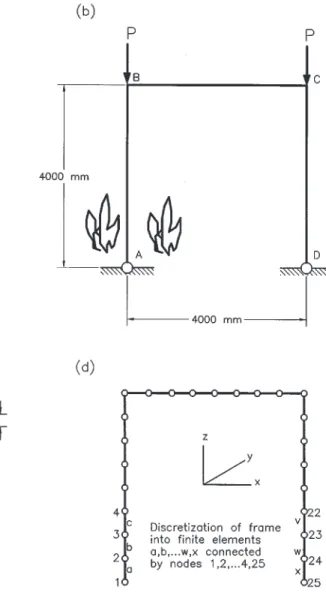
The geometry and dimensions of the column and frame used in the analysis are shown in Figs. 2a and 2b, with the shape and dimensions of the cross section of the structural members (columns and beams) depicted in Fig. 2c. A full frame was used in this study because of the nonsymmetric nature of the problem arising from the heat load, which was applied uniformly to only one column (column AB, Fig. 2b). The column and frame were discretized using a two-node beam element. Figure 2d shows a typical finite element discretization used for the analysis of the portal frame. The
element has three translational (tx, ty, tz) and three rotational (rx, ry, rz) degrees of freedom (DOF) at each of the nodes. Since the x–z plane constitutes the plane of the frame and the column, to be consistent with one of the assumptions to be stated later, that there is no deformation of the column heads normal to the plane of the frame, all translational DOF in the y direction and the rotational DOF about the x axis were restrained throughout the analysis. All other boundary conditions were applied depending on whether the frame was pinned-based (braced or unbraced) or fixed-based (braced or unbraced).
The analysis was carried out for the following cases: (1) an isolated pinned-ended column, (2) pinned-based por-tal frame without sway, (3) fixed-based porpor-tal frame without sway, (4) pinned-based portal frame with sway permitted, and (5) fixed-based portal frame with sway permitted.
The applied load on the column was 742 kN and remained constant throughout the analysis. The same load was applied at each column head for the frame analysis.
Assumptions
The following assumptions were used in the analyses: (1) column AB, as an isolated member and as an integral part of the frame, is uniformly heated across its section and along its entire length; (2) the unheated column CD and beam BC remain at ambient temperature; (3) the vertical loads on the column and on the portal frame are concentric; (4) the frame remains plane, that is, there is no deformation of the column normal to the plane of the frame.
In practice, however, even if the beam is isolated from the heated column, there would be indirect heat flow along the steel at the junction, thereby heating the end of the beam. For assumption 4 to be accomplished, care is taken in the orientation of the elements used in the finite element model-ling. In addition, it was assumed that the members will buckle about their weak axes when loaded and subjected to elevated temperatures. Therefore, the beam and the columns were ap-propriately oriented such that the latter assumption could be achieved.
Properties, materials, and geometry
The columns and the beams of the portal frame are of W150×37 and W250×45 wide flange sections, respectively. The properties of these sections are given in the handbook of the Canadian Institute of Steel Construction (1995) and the dimensions of the column and the frame for the different cases investigated are shown in Fig. 2.
The yield strength (fY0) and modulus of elasticity (E0) of steel at ambient temperature are 300 and 200 000 MPa, re-spectively. For the variation of these properties at high tem-peratures, the relationships proposed by Lie and Macauley (1984) and Lie and Almand (1990) were used.
Analysis procedure
There are usually two steps employed when studying the behaviour of a structural element or any structural assembly in fire. The first step is the calculation of temperature distri-bution in the structure as a function of time, and the second step is the calculation of the structural response at the ele-vated temperature. The exposure temperature distribution as-sumed was similar to that of the standard temperature curve
(ULC 1989). At different times (for example, 3, 5, 10, 15, 25, 30, 35, and 45 min), each temperature value was as-sumed to be uniformly applied to the column as a single member and as an integral part of the frame. In this way, the reduced Young’s modulus at elevated temperature was computed for use in the finite element analysis to determine the buckling load capacity of the column and frame as the temperature increased with time. The structural response (strength of structure) can be determined, either by using the critical temperature method, by an approach based on load deflection (stress–strain relations), or by stability analysis. The stability approach is presented in this paper for the study of the behaviour of a column and a frame in fire.
Buckling analysis
Before the analysis was carried out, a convergence study to determine the number of elements required for the finite element discretization was conducted. Based on this study, it was realized that eight elements on both the column and
beam would be sufficient to give accuracy in the structural stability problem that is adequate for practical purposes.
In the analysis, the maximum load that the column or the frame could support prior to instability or collapse as the temperature is increased is computed. The finite element for-mulation of the buckling problem is based on the matrix dis-placement method (Bathe 1982; Yang 1986; Zienkiewicz 1977), in which the primary unknowns were the generalized displacements (translations and rotations). These are related to the generalized forces (forces and moments) by the fol-lowing relationship:
[1] {F} = [K]{Q}
in which {F} is a vector containing the structure’s general-ized forces, [K] is the structure’s stiffness matrix, and {Q} is a vector containing the generalized structural displacements. They are obtained by assembling the element force vector, {f}, the element stiffness matrix, [k], and the element dis-placement vector, {q}, respectively.
Fig. 2. Column, frame, cross section, and finite element discretization for example 1: (a) single column, case 1; (b) portal frame, cases
2–5; (c) cross section; and (d) idealization for analysis. All dimensions are in millimetres; beam (column) = W250×45 (W150×37); yield stress = 300 kN/mm2.
The stiffness matrix of an element [k] is composed of two separate matrices: (i) the normal stiffness matrix associated with the bending deflection; and (ii) the geometric (or initial stress) stiffness matrix associated with the effect of the axial force on bending deflection. The geometric stiffness matrix allows for the destabilizing effect of the axial loads. For the whole structural system, the stiffness matrix is the sum of the normal, [K]S, and geometric, [K]G, stiffness matrices: [2] [K] = [K]S + [K]G
The point of instability occurs when the determinant of this overall stiffness matrix becomes zero:
[3] det[K] = 0
The calculation of buckling load with temperature rise is carried out in three stages. In the first stage, the deflections and stresses associated with the applied load are determined. These stresses are then used in the second stage to form the geometric stiffness matrix [K]G. Finally, the overall normal stiffness matrix [K]S and the geometric stiffness matrix are then used in the following equation:
[4] {[K]S + λ[K]G}{Q} = 0
in whichλis the unknown buckling load multiplier, and {Q} is the matrix describing the unknown buckling mode shape.
An eigenvalue solution process is employed to compute the buckling load multiplier,λ, which is the ratio of buckling load (Pcr) to the applied load (P) and {Q}.
Example 2
Problem definition
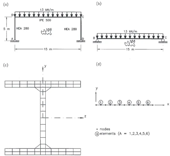
The structure considered is a one-storey frame previously analysed by Franssen and Dotreppe (1992) using the com-puter program CEFICOSS (comcom-puter engineering of the fire design of composite and steel structures). The frame with the finite element idealization, as illustrated in Fig. 3, was exposed to standard fire (ISO 1985) and analysed with SAFIR to obtain the time–deflection response as the heating progresses. In this analysis, all the members in the frame are heated during the entire duration of the analysis. The col-umns are assumed to be heated on all sides, whereas the beams are heated on three sides.
The beam of the frame (beam BC) has also been analysed as a single member for three-support conditions, namely, simple supports, rotational restraints, and axial end re-straints, to determine their influence on the fire resistance of steel beams.
Fig. 3. Frame, beam, and finite element discretization for example 2 (yield stress = 300 kN/mm2): (a) beam BC (as part of frame); (b) beam BC (as a single member); (c) typical section discretization for thermal analysis; and (d) typical member discretization for structural analysis.
Structure idealization and analysis procedure
The analysis was carried out using the computer program SAFIR, which was developed for the analysis of structures under fire conditions and is based on finite element method formulation. For thermal analysis, the cross sections of beams and columns are discretized with rectangular or trian-gular mesh and for structural analysis the beam and column members are discretized along their lengths.
Varying material properties in element can be used in the analysis, and this facilitates the analysis of steel, plane con-crete, or composite (steel–concrete or reinforced concrete) structures. The fire temperature, defined as a function of time, can be represented by either standard curves (ISO
1985; or ASTM 1990) or realistic fire growth curves which can be provided as input to the program.
The first stage in the analysis involves defining the tem-peratures in the cross sections of the members. Thus, the eventual presence of insulating materials, the moisture in concrete, and temperature-dependent material properties can be considered in the analysis. The second stage is the struc-tural analysis, in which temperatures from the thermal analy-sis are used as input to determine the mechanical behaviour of the structure. Various stress–strain relations are built into the program and thermal strain effects can be accounted for. Creep is implicitly included in the stress–strain relations. Residual stresses as well as large displacement effects can be considered.
The validity of SAFIR was carried out by comparing predictions from the model with test data by Rubert and Schaumann (1986), and good agreement between the test data and the model predictions was obtained (Nwosu et al. 1998).
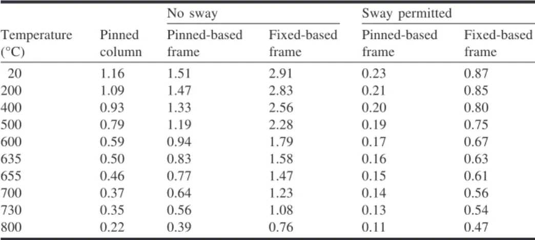
Table 1 summarizes the values of the buckling load multi-plier (λ) at various temperatures for the fire cases analysed. The results show that for all sway-permitted cases in the frame, the critical loads were lower than the applied load. This shows the importance of restraint against side sway in a frame if structural members are to have enhanced fire resis-tance performance when they are acting as an integral part of the frame.
Figure 4 (example 1) shows the variation of the buckling load multiplier with temperature for the pinned-ended tion for column and sway and nonsway pinned-based condi-tions for the frame. For the pinned-ended column acting as a single member, the buckling load was less than the 742 kN at about 400°C, whereas for the nonsway pinned-based frame the corresponding buckling load less than 742 kN was found at about 600°C. This translates into higher fire resis-tance of the column when it is an integral part of the frame. Also included in Fig. 4 (example 1) is the case where the frame is not braced against sway. In this situation, the fire resistance of the column as an isolated member is higher than that when it is a part of the frame. This indicates that
No sway Sway permitted
Temperature (°C) Pinned column Pinned-based frame Fixed-based frame Pinned-based frame Fixed-based frame 20 1.16 1.51 2.91 0.23 0.87 200 1.09 1.47 2.83 0.21 0.85 400 0.93 1.33 2.56 0.20 0.80 500 0.79 1.19 2.28 0.19 0.75 600 0.59 0.94 1.79 0.17 0.67 635 0.50 0.83 1.58 0.16 0.63 655 0.46 0.77 1.47 0.15 0.61 700 0.37 0.64 1.23 0.14 0.56 730 0.35 0.56 1.08 0.13 0.54 800 0.22 0.39 0.76 0.11 0.47
Notes: Applied load = 742 kN; buckling load = 742λkN.
Table 1. Buckling load multiplier (λ= Pcr/P) at various temperatures.
Temperature (oC ) 0 100 200 300 400 500 600 700 800 900 1000 P cr / P 0.0 0.5 1.0 1.5 2.0
pinne d-e nde d column pinne d-ba s e d fra me (no s wa y) pinne d-ba s e d fra me (s wa y pe rmitte d) Fig. 4. Buckling load multiplier as a function of temperature
the restraint of structures against lateral movement is impor-tant when considering the survival of that structure in fire conditions. Therefore, the enhancement of the column fire resistance could only be achieved when it is in a sway-prevented frame, which is the case in real practice.
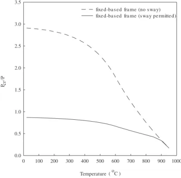
Figure 5 (example 1) shows the buckling load multiplier plotted against temperature for the case of a fixed-based frame, both braced and unbraced. Again the performance of the column in the fire is much more enhanced for the nonsway situation than for the unbraced case. The enhanced performance of the braced fixed-based frame over the un-braced frame is more obvious at temperatures between 20°C (ambient temperature) and 600°C. At 20°C, the buckling load multipliers are 1.16, 1.51, 2.91, and 0.87 for the single pinned-ended column, braced pinned-based frame, braced fixed-based frame, and unbraced fixed-based frame, respec-tively. This result indicates that the buckling load for the column in the fixed frame, with sway prevented, is about three times that of the pinned-end column acting as a single member in ambient temperature conditions. At an elevated temperature of about 400°C, the buckling load multiplier for the pinned-end isolated column is 0.93, whereas that of the fixed-based frame for the nonsway condition is 2.57, indi-cating that at this temperature (400°C) the single column is already at the verge of collapse, whereas the same column in the fixed frame condition can still maintain a load of about 2.5 times the applied load before buckling.
Figure 6 (example 1) shows the results of this study plot-ted in a bar chart to illustrate the time taken for the isolaplot-ted column and the pinned- and fixed-based frames without sway to attain instability in fire. If it is hypothetically as-sumed that failure of any of the above structural systems (the column and the frames) occurs in fire when the critical buckling load is attained, then the resistance times of the pinned- and fixed-based frames (nonsway situation) will be
higher than that of the isolated column. Figure 6 shows that, although the buckling load of the isolated column is about 80% of the applied load in 10 min at a temperature of 500°C, it takes approximately 25 and 45 min at temperatures of 650 and 800°C for the pinned- and fixed-based frames, respectively, to reach the same percentage of the applied load. This shows that the fire resistance of the column is im-proved when it is part of a structural system. The improve-ment in the fire resistance of the column while acting as an integral part of the frame is as a result of continuity, intertion of members, and the restraint acintertion present in the ac-tual system.
Figure 7 (example 2) shows the vertical deflections at the centre of beam BC as a single simply supported member and as a member of the frame. At the end of the analysis (17 min) for the beam acting as a single member, the midspan had deflected 1700 mm. At this same time (17 min), the midspan deflection of the beam as a member of the frame is 485 mm for the pinned-based condition and 332 mm for the fixed-base condition. Assuming that the lim-iting central deflection is L/30 or L/20, then the deflection of the beam as a single member (1700 mm) is greater than the deflection limit (L/20 = 750 mm or L/30 = 500) at failure time (17 min). On the other hand, the deflection of the beam as a member of the frame for both pinned- and fixed-based cases (485 and 332 mm, respectively) is less than the deflec-tion limit (L/20 = 750 mm or L/30 = 500 mm) at 17 min. Therefore, there is an enhancement in the beam resistance to fire when it is considered as an integral part of the frame compared with that as a single member. This improvement in the performance of the beam as a member of the frame is due to continuity between the beam and the columns.
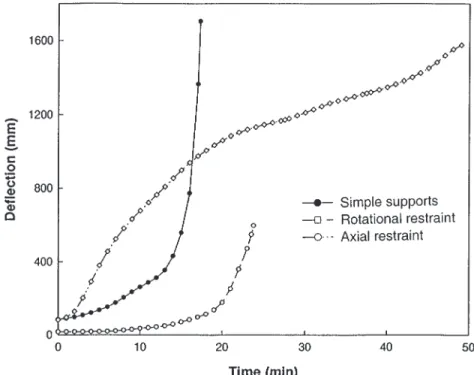
Figure 8 (example 2) shows the variation of midspan de-flection of beam BC as a single member under three types of restraint conditions, and illustrates the effect of end restraint Temperature (oC ) 0 100 200 300 400 500 600 700 800 900 1000 P cr / P 0.0 0.5 1.0 1.5 2.0 2.5 3.0 3.5
fixe d-ba s e fra me (no s wa y) fixe d-ba s e fra me (s wa y pe rmitte d)
d d
Fig. 5. Buckling load multiplier as a function of temperature
(fixed-base conditions: example 1).
Time (min) -10 0 10 20 30 40 50 60 P c r / P 0.0 0.5 1.0 1.5 2.0 2.5 3.0 pinne d column
pinne d-ba s e d fra me (no s wa y) fixe d-ba s e d fra me (no s wa y) Fig. 6. Variation of buckling load as a function of time
on the performance of a loaded steel beam in fire. The effect of providing axial restraint resulted in large midspan deflec-tions early in the heating process, and is attributed to the lack of allowance for axial expansion. A deflection of L/30 (500 mm) was reached after 7 min in the axial restraint con-dition compared with 14 and 23 min for simply supported and rotational restraint conditions, respectively. With a fur-ther increase in temperature, the rate of increase in midspan deflection for the axial restraint conditions is greater than that exhibited by the simply supported and rotational
re-straint conditions, until about 15 min. Failure in the simply supported beam occurred at about 17 min with the lower flange temperature of 580°C. For the rotational restraint con-dition, the failure time increase to 24 min with the lower flange temperature of 720°C, while the axial restraint condi-tion had a failure time of 49 min and a lower flange temper-ature of 900°C.
Figure 9 (example 2) shows the vertical deflection at the top of column CD for two end conditions (pinned-based and fixed-based) for the frame. The column for the pinned-end Fig. 7. Variation of vertical midspan deflection of beam BC in example 2 (single beam and beam in frame).
condition failed at about 17 min while that for the fixed-based condition failed at about 19 min. The increase in the vertical displacement at the top of the column before buck-ling in both cases is due to thermal elongation. This dis-placement, as seen in Fig. 9, rapidly goes to zero when buckling starts, and this demonstrates that the computer pro-gram SAFIR is a real simulation tool, since this is what is observed in a fire test.
Based on the information given above, the following con-clusions can be drawn:
• The fire resistance behaviour of a complete structure is different from that of a single structural member. • By considering factors such as structural interaction,
end restraint, continuity, and membrane action of the floor slab when analysing a complete structure under fire, better performance of a structure can be obtained. This is likely to lead to reduction in the cost of fire pro-tection.
• The examples presented shows that there is an improved performance of a member in fire if it is considered as an integral part of a frame rather than as a single member. It is shown (in example 1) that, at a temperature of about 400°C, the buckling load capacity of the fixed-based nonsway frame was approximately three times that of the pinned-based isolated column at the same temperature.
• End restraints, rotational or axial, generally increase the time before collapse of a beam in a fire.
• The design of a steel structure against fire based on its complete structural behaviour rather than on single members reflects the realistic scenario and is beneficial from the point of view of fire resistance.
The second author wishes to acknowledge the financial assistance provided by the North Atlantic Treaty Organisa-tion through NATO Collaborative Research award.
ASTM. 1990. Standard method of fire tests of building construc-tion materials. Standard ASTM E119-83, American Society for Testing and Materials, Philadelphia, Pa.
Bailey, C.G., Burgess, I.W., and Plank, R.J. 1996. Computer simu-lation of a full-scale structural fire test. The Structural Engineer,
74: 93–100.
Bathe, K.J. 1982. Finite element procedures in engineering analy-sis. Prentice-Hall Inc., Englewood Cliffs, N.J.
Canadian Institute of Steel Construction. 1995. Handbook of steel construction. 6th ed. Canadian Institute of Steel Construction, Willowdale, Ont.
Cooke, G.M.E., and Latham, D.J. 1987. The inherent fire resis-tance of a loaded steel framework. Steel Construction Today, 1: 49–58.
El-Rimawi, J.A. 1993. NARR2: a program for the structural analy-sis of 2-D frames at elevated temperature. Research Report, Department of Civil and Structural Engineering, University of Sheffield, Sheffield, United Kingdom.
El-Rimawi, J.A., Burgess, I.W., and Plank, R.J. 1994. Model stud-ies of composite building frame behaviour in fire. Fire Safety Science — Proceedings of the 4th International Symposium, Ottawa, Ont., June 1994, pp. 1137–1148.
Franssen, J.M., and Dotreppe, J.C. 1992. Fire resistance of col-umns in steel frames. Fire Safety Journal, 19: 159–175. Franssen, J.M., Cooke, G.M., and Latham, D.J. 1995. Numerical
simulation of a full scale fire test on loaded steel framework. Journal of Constructional Steel Research, 35: 377–408.
ISO 1985. Fire resistance tests — element of building construction. ISO 834, International Standard Organization.
Kemp, K.O. 1967. Yield of a square reinforced concrete slab on simple supports, allowing for membrane forces. The Structural Engineer, 45: 235–240.
Kirby, B.R. 1997. Large scale fire tests: the British Steel European Collaborative Research Programme on the Building Research Establishment 8-storey frame. Fire Safety Science — Proceed-ings of the 5th International Symposium, Melbourne, Australia, March 1997, pp. 1129–1140.
Lawson, R.M. 1990. Behaviour of steel beam-to-column connec-tions in fire. The Structural Engineer, 68: 263–271.
Lennon, T. 1996. Large compartment fire test. Proceedings of the 2nd Cardington Conference on Fire, Static and Dynamic Tests at the Large Building Test Facility, 12–14 March 1996, Cardington, United Kingdom, pp. 45–53.
Leston-Jones, L.C., Burgess, I.W., Lennon, T., and Plank, R.J. 1997. Elevated-temperature moment–rotation tests on steelwork connections. Proceedings of the Institution of Civil Engineers: Structures and Buildings, 122: 410–419.
Lie, T.T., and Almand, K.H. 1990. A method to predict the fire resistance of steel building columns. Engineering Journal of the American Institute of Steel Construction, 27: 158–167. Lie, T.T., and Macauley, B.A. 1984. Evaluation of the fire
resis-tance of protected steel columns. Division of Building Research, National Research Council of Canada, Ottawa, Ont., DBR Paper 1167, NRCC 23065.
Nwosu, D.I., and Kodur, V.K.R. 1997. Steel structures exposed to fire — a state-of-the-art report. Institute for Research in Con-struction, National Research Council of Canada, Ottawa, Ont., Internal Report No. 749, pp. 1–32.
Nwosu, D.I., Kodur, V.K.R., and Franssen, J.M. 1998. A user’s manual for computer program SAFIR. National Research Coun-cil of Canada, Ottawa, Ont., Internal Report. In press.
Rubert, A., and Schaumann, P. 1986. Structural Steel and plane frame assemblies under fire action. Fire Safety Journal, 10: 173–184.
ULC. 1989. Standard methods of fire endurance tests of building construction and materials. Standard CAN/ULC-S101-M89, Underwriters’ Laboratories of Canada, Scarborough, Ont. Wang, Y.C. 1996. Tensile membrane action in slabs and its
appli-cation to the Cardington tests. Proceedings of the 2nd Cardington Conference on Fire, Static and Dynamic Tests at the Large Building Test Facility, 12–14 March 1996, Cardington, United Kingdom, pp. 55–68.
Wang, Y.C., Lennon, T., and Moore, D.B. 1995. Behaviour of steel frames subject to fire. Journal of Constructional Steel Research,
35: 291–322.
Yang, T.Y. 1986. Finite element structural analysis. Prentice-Hall, Inc., Englewood Cliffs, N.J.
Zienkiewicz, O.C. 1977. The finite element method. 3rd ed. McGraw-Hill Book Company, London, United Kingdom.