Capturing the Human Figure Through a Wall
by
Chen-Yu Hsu
B.S., National Taiwan University (2013)
Submitted to the Department of Electrical Engineering and Computer Science
in partial fulfillment of the requirements for the degree of
Master of Science in Computer Science and Engineering
at the
MASSACHUSETTS INSTITUTE OF TECHNOLOGY
February 2017
Massachusetts Institute of Technology 2017. All rights reserved.
Signature redacted
A u th o r . . . ... . . . . ...
Department of Electrical Engineering and Computer Science
December 20, 2016
Certified by...
Accepted by
MASSACHUSETTS NSTITUTE OF TEgUN LYMAR 13
2017
LIBRARIES
Signature redacted
Dina Katabi
Professo
f Electrical Engineering and Computer Science
Thesis Supervisor
Signature redacted
/
0(I-eslie A. Kolodziejski
Professor of Electrical Engineering and Computer Science
Chair, Department Committee on Graduate Theses
Capturing the Human Figure Through a Wall
by
Chen-Yu Hsu
Submitted to the Department of Electrical Engineering and Computer Science on December 20, 2016, in partial fulfillment of the
requirements for the degree of
Master of Science in Computer Science and Engineering
Abstract
We present RF-Capture, a system that captures the human figure - i.e., a coarse skeleton - through a wall. RF-Capture tracks the 3D positions of a person's limbs and body parts even when the person is fully occluded from its sensor, and does so without placing any markers on the subject's body. In designing RF-Capture, we built on recent advances in wireless research, which have shown that certain radio frequency (RF) signals can traverse walls and reflect off the human body, allowing for the detection of human motion through walls. In contrast to these past systems which abstract the entire human body as a single point and find the overall location of that point through walls, we show how we can reconstruct various human body parts and stitch them together to capture the human figure. We built a prototype of RF-Capture and tested it on 15 subjects. Our results show that the system can capture a representative human figure through walls and use it to distinguish between various users.
Thesis Supervisor: Dina Katabi
Disclaimer
This project is joint work with another graduate student, Fadel Adib. The algorithms presented in this thesis were developed during brainstorming sessions between me and Fadel. I was responsible for the implementation and empirical evaluation of the system. I really enjoyed working with Fadel and appreciate all the help.
Acknowledgments
I am deeply indebted to my advisor, Dina, for influencing me the way to do research. I learned her passion
for finding answers to the unknowns and building systems with real impact. I thank her for her patience to spend a huge amount of time brainstorming with me, listening to my ideas, and challenging my way of thinking. Without her help and guidance, the work in this thesis would not be possible.
I also want to thank Fadel for being my mentor in my first year of graduate school. He not only showed
me the ropes of doing research but also taught me the way to become a successful graduate student. I still remember the countless nights we spent in the lab debugging our system and the crazy ideas that we came
up with while walking back to dorms together after mid-night.
I am really grateful for being a part of NETMIT and working with amazing colleagues/friends. I am
thankful to Zach for his insights on hardware and signals and also for being the nicest person I have met. Haitham and Omid always give me the best advice whenever I come to them. I also want to thank Rumen, Emad and Tommy for the good times we had solving exciting problems and building systems together.
I owe my thanks to Deepak, Mingmin, Ezz, Rahul, Lixin, Swarun, and Shichao for their friendship and
insightful discussions on various research topics. Many thanks to Mary for taking care of our orders always the fastest possible.
Outside of the lab, I want to thank all my friends for their warm companionship when I was lost and frustrated. They made my life at MIT much easier and more colorful than it would otherwise. I also owe my special thanks to Michelle for always being there to support me.
Lastly, but most importantly, I want to thank my family for their never-ending love and support. I dedicate this thesis to them.
Contents
1 Introduction 10
2 Related Work 13
2.1 Motion Capture Systems . . . . 13
2.2 Imaging and Reconstruction Algorithms . . . . 14
2.3 Radar Systems . . . . 14
2.4 Device-Free Localization and Gesture Recognition . . . . 15
3 Primer 17 3.1 Phase of RF signals . . . . 17
3.2 Antenna Arrays . . . . 17
3.3 FMCW Frequency Chirps. . . . . 18
3.4 Eliminating Static Reflectors . . . . 19
4 RF-Capture Overview 20 4.1 T he device . . . . 20
4.2 The challenge . . . . 20
4.3 The solution idea . . . 21
5 Coarse-to-Fine 3D Scan 23 5.1 Coarse-to-Fine Angular Scan . . . . 24
5.2 Coarse-to-Fine Depth Scan . . . . 24
6 Motion-based Figure Capture 6.1 Compensating for Depth
6.2 Compensating for Sway .
6.3 Body Part Segmentation 6.4 Skeletal Stitching . 7 Implementation 7.1 Hardware . . . . 7.2 Software . . . . 7.3 Calibration . . . . 8 Evaluation Environment 8.1 Participants . . . . 8.2 Experimental Environment . . . . 8.3 B aseline . . . . 9 Results
9.1 Body Part Identification and Tracking . . . .
9.1.1 Body Part Identification . . . .
9.1.2 Body Part Tracking . . . .
9.2 Human Figure Capture and Identification . . . .
9.2.1 Amount of Motion Required for Figure Capture . . . .
9.2.2 Sample Captured Figures . . . .
9.2.3 Human Identification . . . . 10 Conclusion . . . . . . . . . . . . . . . . 28 30 30 31 33 35 35 36 36 37 37 37 37 39 39 39 41 42 42 43 44 47
List of Figures
1-1 Through-wall Capture of the Human Figure. The sensor is placed behind a wall. It
emits low-power radio signals. The signals traverse the wall and reflect off different ob-jects in the environment, including the human body. Due to the physics of radio reflections, at every point in time, the sensor captures signal reflections from only a subset of the hu-man body parts. We capture the huhu-man figure by analyzing multiple reflection snapshots across time and combining their information to recover the various limbs of the human body. 11
3-1 Measuring Location with RF Signals. (a) Antenna arrays can be used to focus on signals
from a specific direction 0. (b) FMCW chirps can be used to obtain time-of-flight (i.e.,
depth) m easurem ents. . . . . 18
4-1 RF Reflections. (a) Only signals that fall along the normal to the surface are reflected
back toward the device. (b) The human body has a complex surface, but at any point in time only signals close to the normal to the surface are reflected back toward the device. (c) As the person walks, different body parts reflect signals toward the device and become visible to the device. . . . 21
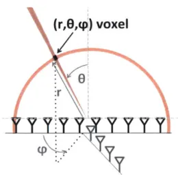
5-1 Scanning. A 2D antenna array with FMCW ranging can focus on any (r, 0, 0) voxel in 3D. 24
5-2 Coarse-to-Fine Angular Scan. We start by using a small number of antennas which gives
us a wide beam and coarse angular resolution. Then, we refine our estimate by using more antennas to achieve a narrower beam and finer resolution, but use that beam only to scan regions of interest. . . . . 25
5-3 Coarse-to-Fine Depth Scan. We start by using a small chunk of bandwidth which gives
us coarse depth resolution. Then, we refine our estimate by adding more bandwidth to achieve finer resolution, but use that bandwidth only to scan regions of interest. . . . 26
5-4 Coarse-to-Fine 3D Scan. We can partition and iterate jointly using chirps and antenna
arrays. In any given iteration, we only scan the small region identified by the previous iteration. . . . . 26
6-1 RF-Capture's heatmaps and Kinect skeletal output as a user walks toward the
de-ployed sensors. As the user walks toward the device, RF-Capture captures different parts
of his body at different times/distances since its antennas' perspective changes with re-spect to his various body parts. We rotate the Kinect output by 450 to visualize the angles of the limbs as the user moves. . . . . 29 6-2 Body Part Segmentation and Captured Figure. (a) shows the different regions used to
identify body parts, and (b) shows the captured synthesized from 25 time frames. . . . . . 33
7-1 RF-Capture's Hardware Schematic. The setup consists of a chirp generator connected
to a 2D antenna array via a switching platform. The figure shows the Tx chain, and two of the R x chains. . . . . 36
9-1 Body Part Identification Accuracy with Distance. The figure shows RF-Capture's
ac-curacy in identifying the moving body part as a function of the user's distance to the device. 40
9-2 Tracking the Human Hand Through Walls. RF-Capture tracks the subject's palm
through a wall while the Kinect tracks it in line-of-sight. . . . 41
9-3 Body Part Tracking Accuracy. The figure shows the CDF of RF-Capture's accuracy in
tracking the 3D trajectory of the subject's hand. . . . 41
9-4 Writing in the Air. The figure shows the output of RF-Capture (in blue) and Kinect (in
red) for two sample experiments were the subject wrote the letters "S" and "U" in mid-air. 42
9-5 Body Part Detection Accuracy. In these experiments, the user walks in exactly two
steps. The figure shows the percentage of experiments during which RF-Capture was able
9-6 Human Figures Obtained with RF-Capture. The graphs show examples of the human
figures generated by RF-Capture. Each column shows a different human subject, while each row shows figures of the same subject across different experiments. . . . 44
9-7 Identification Accuracy as a Function of the Number of Users. RF-Capture uses the
captured figures to identify users through classification. The accuracy decreases as the number of users we wish to classify increases. . . . . 46
Chapter 1
Introduction
Capturing the skeleton of a human body, even with coarse precision, enables many applications in com-puter graphics, ubiquitous computing, surveillance, and user interaction. For example, solutions such as the Kinect allow a user to control smart appliances without touching any hardware through simple ges-tures, and can customize their behavior by recognizing the identity of the person. Past work on skeletal acquisition has made significant advances in improving precision; however, all existing solutions require the subject to either carry sensors on his/her body (e.g., IMUs, cameras) or be within the line of sight of an external sensor (e.g., structured light, time of flight, markers+cameras). In contrast, in this thesis, we focus on capturing the human figure - i.e., coarse human skeleton - but without asking the subject to wear any sensor, and even if the person is behind a wall.
To achieve this goal, we build on recent advances in wireless research, which have shown that RF (Radio Frequency) signals can be used to find the location of a person from behind a wall, without requiring the person to hold or wear any device [6, 51, 41, 11]. These systems operate in a fashion similar to Radar and Sonar, albeit at much lower power. They emit wireless signals at very low power (1/1000 of WiFi) in a frequency range that can traverse walls; the signals reflect off various objects in the environment, including the human body, and they use these reflections to localize the person at any point in time. However, all past systems capture very limited information about the human body. Specifically, either they abstract the whole human body as a single-point reflector, which they track [6, 7, 51, 41], or they classify a handful of forward-backward gestures by matching them against prior training examples [45].
The challenge in using RF to capture a human figure is that not all body parts reflect the signal back to the sensors. Specifically, at frequency ranges that traverse walls, human limb curves act as ideal reflectors;
F _CAPTURE ALGORITHM
Sensor is Placed Behind a Wall Snapshots are Collected across Time Captured Human Figure
Figure 1-1: Through-wall Capture of the Human Figure. The sensor is placed behind a wall. It emits low-power radio signals. The signals traverse the wall and reflect off different objects in the environment, including the human body. Due to the physics of radio reflections, at every point in time, the sensor captures signal reflections from only a subset of the human body parts. We capture the human figure by analyzing multiple reflection snapshots across time and combining their information to recover the various limbs of the human body.
hence, they may deflect the signal away from the sensors rather than back to them. (This is because RF signals that traverse walls have a wavelength of multiple centimeters, which is larger than the surface roughness of human body parts, causing each part to act as a perfect reflector [10].) At every point in time, the RF sensors capture signals from only a subset of the human body parts, and the sensors lack semantics to understand which body part is reflecting the signal back at that instant. Furthermore, as a person moves, the reflecting limbs vary; for example, at some point, a person's left hand may reflect the signal back but not his right hand or his head, while at other times, his head may reflect the signal back but neither of his hands. To overcome this challenge, past systems that use radar techniques to reconstruct a skeleton require surrounding the human body with a very large antenna array that can capture the reflections off his/her body parts, similar to holographic systems deployed in airports.
In this thesis, we limit ourselves to a compact antenna array that sits in a corner of a room - like
a Kinect sensor - and captures the figure of a person behind a wall, as shown in Fig. 1-1. We present
RF-Capture, the first system that can capture the human figure when the person is fully occluded (i.e., in the absence of any path for visible light). RF-Capture has two main algorithmic components: The first component is a coarse-to-fine algorithm that efficiently scans 3D space looking for RF reflections of various human limbs and generating 3D snapshots of those reflections. The second component exploits the
I
fact that due to human motion, consecutive RF snapshots tend to expose different body parts and diverse perspectives of the same body part. Thus, this component introduces an algorithm that identifies human body parts from RF snapshots across time, and stitches multiple snapshots together to capture the human figure.
We leverage the captured figure to deliver novel capabilities. First, we show how the captured figure can be incorporated into a classifier to identify different subjects from behind a wall. Our classification accuracy is 95.7% when distinguishing between 5 users, and becomes 88.2% for 15 users. Second, we show that RF-Capture can identify which body part a user moves through a wall with an accuracy of
99.13% when the user is 3 m away and 76.4% when the user is 8 m away. Finally, we show that
RF-Capture can track the palm of a user to within a couple of centimeters, tracing letters that the user writes in the air from behind a wall.
We believe the above results present a significant leap towards human figure capture through walls and full occlusion. However, the current system still has limitations. First, our current model assumes that the subject of interest starts by walking towards the device, hence allowing RF-Capture to capture consecutive RF snapshots that expose various body parts. Second, while the system can track individual body parts facing the device, such as a palm writing in the air, it cannot perform full skeletal tracking. This is because not all body parts appear in all RF snapshots. We believe these limitations can be addressed as our understanding of wireless reflections in the context of computer graphics and vision evolves.
Chapter 2
Related Work
2.1
Motion Capture Systems
Past work for capturing the human skeleton relied on motion capture systems that either require instru-menting the human body with markers or operate only in direct line-of-sight to the human body. Specif-ically, marker-based methods place various types of sensors on the human body - including inertial, in-frared, RF, acoustic, or ultrasonic sensors - and capture the human skeleton by tracking these various markers, e.g., [49, 56, 59, 47, 1, 2]. On the other hand, past markerless methods use cameras and infrared-based techniques - including Kinect, multi-view cameras, moving cameras, and time-of-flight cameras
-and require a direct line-of-sight from the sensor to the person's body, e.g., [52, 22, 25, 21, 57, 44, 64].
In contrast to all this past work, RF-Capture focuses on capturing coarse human figures without instru-menting the human body with any markers and operates correctly even if the subject is behind a wall or furniture.
Prior art has also investigated motion capture in partial occlusions, e.g., [34, 27, 36, 43, 12, 58]. How-ever, these systems require the majority of the human body to be unoccluded from their sensors, and focus on estimating the positions of occluded limbs or missing markers by fitting a model. In contrast, since RF-Capture uses RF signals that can traverse occlusions, it works even when the person is fully occluded from its sensor, including scenarios where the subject is behind a wall.
2.2
Imaging and Reconstruction Algorithms
RF-Capture is related to past work on imaging hidden shapes using light that bounces off corner reflectors in the scene [55, 32, 26]. These past systems operate by estimating the time-of-flight of the object's re-flections bouncing off the corner. RF-Capture's reconstruction problem is closely related to such transient imaging techniques; this is because by pointing a time-resolved camera onto a white patch of a wall, that wall essentially becomes a lens-less image sensor with distance information. However, the reconstruction constraints - both in terms of bandwidth and number of sensors - are more stringent in the case of RF-Capture, which limits itself to 20 antennas and less than 2 GHz of bandwidth (while cameras use thousands of pixels and light has hundreds of THz of bandwidth). This allows these transient imaging techniques to achieve higher reconstruction accuracy. Furthermore, in contrast to these systems, RF-Capture only captures specular reflections because of the wavelength of RF signals it uses. However, because it uses RF signals that can traverse occlusions, RF-Capture does not require the placement of corner reflectors in the environment. Furthermore, unlike this past work, it does not require the hidden shape to be fully static during the acquisition time, and hence is evaluated on real human subjects.
Additionally, RF-Capture is related to past work in the Graphics and Vision community on specular object reconstruction [35, 29]. Specifically, for frequencies that traverse walls, reflections off the human body have specular properties. However, past work on specular reconstruction, which operates using visi-ble light, typically assumes the object to be static and non-deformavisi-ble and aims at recovering surface ge-ometry. In contrast, in RF-Capture, the setting is more complex since the object is moving and deformable, but the goal is simpler since we intend to recover a coarse figure as opposed to surface geometry.
2.3
Radar Systems
Radar systems were the first to use RF reflections to detect and track objects. The vast majority of the radar literature focuses on inanimate objects (e.g., planes, metallic structures), as opposed to humans. The radar literature that deals with human subjects can be classified into two categories. The first category is high-frequency imaging radar using terahertz [62], laser [8], or millimeter and sub-millimeter waves [15, 16, 9]. These systems are intrinsically different from ours since they operate at much higher frequencies, where the wavelength is comparable to the roughness of the surface, and hence the human body becomes a
scatterer as opposed to a reflector [10]. The advantage of these systems is that they can image the human skeleton at a high accuracy (as in airport terahertz security scanners). However, they operate at much shorter distances, cannot deal with occlusions like wall or furniture, and are expensive and bulky.
The second category uses centimeter-waves, i.e., its carrier frequency is around few GHz, similar to our system. These systems have significantly lower resolution than our design. In particular, see-through radar estimates the location of a human but does not reconstruct his/her figure [46, 13, 30, 63,
33, 18]. This includes commercial products, like Xaver-100, Xaver-400, Xaver-800, and Range-R [28].
Unlike RF-Capture, these systems cannot track individual limbs or construct a human figure. On the other hand, the few systems that aim to reconstruct the human body demonstrate their results on a doll covered with foil and require an antenna array larger than the imaged object [66]. In comparison to these systems, RF-Capture provides finer resolution, and allows capturing human figures with a granularity that is sufficient for distinguishing between a set of 15 people. Also, RF-Capture limits itself to a compact array about twice the size of a Kinect, as opposed to a large array that is of the size of the human body. In addition, unlike commercial products that target the military [28], which use restricted frequency bands and transmission powers only available to military and law enforcement, RF-Capture meets the FCC regulations for consumer devices.
Finally, RF-Capture's coarse-to-fine algorithm is inspired by radar lock and track systems of military aircraft, which first identify a coarse location of a target then zoom on its location to track it [20]. In contrast to these systems, however, RF-Capture does not separate searching from tracking into different phases at signal acquisition. Additionally, RF-Capture's goal of reconstructing a human figure differs from these past systems, resulting in differences in the underlying algorithms.
2.4
Device-Free Localization and Gesture Recognition
Advances in RF-based indoor localization have led to new systems that can track users without requiring them to carry a wireless transmitter, e.g., [6, 31, 7, 60, 45, 4, 14, 61, 65, 41, 51, 5]. Some of these systems have demonstrated the potential of using RF signals to recognize a handful of forward-backward gestures
by matching them against prior training examples [45]. Others have demonstrated using narrowband RF
signals to map major obstacles and building interiors through walls [17, 40, 23]. RF-Capture builds on this literature but extracts finer-grain information from RF signals. In particular, it is the only system that
can identify which human limb reflects the signal at any time. It is also the only system that can combine those limbs to generate a human figure from behind a wall.
Chapter 3
Primer
3.1
Phase of RF signals
An RF signal is a wave whose phase is a linear function of the traveled distance. By sampling the signal, we can record both its amplitude and its phase. The sampled signal can be represented as a complex discrete function of time t as follows [54]:
s, = A~e A', (3.1)
where r is the distance traveled by the signal, A is its wavelength, and A is its amplitude.
3.2 Antenna Arrays
Antenna arrays can be used to identify the spatial direction from which the RF signal arrives. This process leverages the knowledge of the phase of the received signals to beamform in post-processing as shown in Fig. 3-1(a). Mathematically, an N-element antenna array can compute the power P of signals arriving along the direction 0 as follows [42]:
N
P(O) Zsne] d , (3.2)
where s, is the wireless signal received at the n-th antenna, d is the separation between any two antennas, and A is the wavelength of the RF signal.
Beam Direction 0
Transmitted chirp Reflected chirp
#0 "
e0
6elay-d Time
(a) Antenna Array (b) Frequency Chirp
Figure 3-1: Measuring Location with RF Signals. (a) Antenna arrays can be used to focus on signals from a specific direction 0. (b) FMCW chirps can be used to obtain time-of-flight (i.e., depth) measure-ments.
Furthermore, the larger an antenna array is, the stronger its focusing capability is. Specifically, an
array of length L has a resolution AO = 0.886) [42].
3.3 FMCW Frequency Chirps
Frequency Modulated Carrier Wave (FMCW) is a technique that allows a radio device to measure the
depth of an RF reflector. An FMCW device transmits a frequency chirp -i.e., a periodic RF signal whose
frequency linearly increases in time, as shown in Fig. 3-1(b). The chirp reflects off objects in the environ-ment and travels back to the device after the time-of-flight. The device can measure the time-of-flight and use it to infer the depth of the reflector. To do so, the device leverages the linear relationship between time and frequency in chirps. Specifically, it measures the time-of-flight (and its associated depth) by measur-ing the frequency shift between the transmitted and received signal. Mathematically, a frequency chirp of slope k can be used to compute the signal power P emanating from a particular depth r as follows [38]:
T
P(r) = Zsse2lt , (3.3)
t=1
where st is the baseband time signal, c is the speed of light, and the summation is over the duration T of each chirp.
Specifically, a frequency chirp of bandwidth B has a depth resolution Ar = [38].
3.4 Eliminating Static Reflectors
To capture the human figure, we first need to separate human reflections from the reflections of other objects in the environment (e.g., walls and furniture). To do so, we use standard background subtraction, where subtraction is performed in the complex domain since an RF signal is a sequence of complex numbers (with magnitude and phase). Specifically, reflections of static objects remain constant over time and can be eliminated by subtraction. Hence, we collect the reflections of static objects before any human enters the room and subtract them from the received chirps at later times. Of course, this requires knowing whether there are humans in the room or not, which we achieve by leveraging past work on RF-based device-free localization which accurately detects and localizes humans [6].
Chapter 4
RF-Capture Overview
4.1 The device
RF-Capture is a system that captures the human figure - i.e., a coarse human skeleton - through walls. It operates by transmitting low-power RF signals (1/1000 the power of WiFi), capturing their reflections off different objects in the environment, and processing these reflections to capture the human figure. RF-Capture's prototype consists of a T-shaped antenna array, as shown in Fig. 1-1. The vertical segment of the "T" consists of transmit antennas and the horizontal segment of the "T" consists of receive antennas. The antennas are connected to an FMCW transceiver which time-multiplexes its transmission between the different transmit antennas, and which can be operated from a computer using a USB cable. The total size of the antenna array is 60 x 18 cm2.
In contrast to typical techniques for imaging humans such as visible light, x-ray, terahertz, and millimeter-wave, RF-Capture operates at lower frequencies between 5.46GHz and 7.24GHz. The advantage of op-erating at such relatively low RF frequencies is that they traverse walls. Additionally, opop-erating at these frequencies allows us to leverage the low-cost massively-produced RF components in those ranges.
4.2
The challenge
The key challenge with operating at this frequency range (5-7GHz) is that the human body acts as a reflector rather than a scatterer. As a result, at any point in time, our antenna array can capture only a subset of the RF reflections off the human body. To see why this is the case, consider the simplified
Cannot Capture Reflecflon
(a) Simple Reflector (b) Reflections off Human Body (c) Exploiting Motion to Capture Various Body Parts
Figure 4-1: RF Reflections. (a) Only signals that fall along the normal to the surface are reflected back toward the device. (b) The human body has a complex surface, but at any point in time only signals close to the normal to the surface are reflected back toward the device. (c) As the person walks, different body parts reflect signals toward the device and become visible to the device.
example in Fig. 4-1(a). Recall the basic reflection law: reflection angle is equal to the angle of incidence. Thus, while an antenna array can transmit signals towards the reflecting body, only signals that fall close to the normal to the surface are reflected back toward the array. In contrast, signals that deviate from the normal to the surface are deflected away from our array, making those parts of the reflector invisible to our device. The human body has a much more complex surface; however the same principle still applies, as illustrated in Fig. 4-1(b).
4.3 The solution idea
Our solution to the above problem exploits user motion to capture his figure. Specifically, while the antenna array receives reflections only from very few points on the user's surface, these points vary as the person moves, and trace the person's body. Fig. 4-1(b) and (c) illustrate this concept. The figures show that as the person walks, the relation between the incident signal and the normal to the surface for his various body parts naturally changes, providing opportunities for capturing the signals reflected from various body parts. Hence, we could capture the instantaneous RF reflections over consecutive time frames, relate them to each other to identify which reflections are coming from which body part, and combine their information across time and motion to capture the human figure.
In order to transform the above idea into a practical system, we need a design that satisfies two require-ments: on one hand, the system needs to achieve spatial resolution sufficient for constructing the human figure; on the other hand, the system should process the signals in real-time at the speed of its acquisition (as in Kinect).
The design of RF-Capture harnesses the above idea while satisfying our design requirements. Specifi-cally, the system has two key components:
e Coarse-to-fine 3D Scan: This component generates 3D snapshots of RF reflections by combining
an-tenna arrays with FMCW chirps. A key consideration in designing this algorithm is to ensure low computational complexity. Specifically, directly scanning each point in 3D space to collect its reflec-tions is computationally intractable. Thus, this component introduces a coarse-to-fine algorithm that
starts by scanning 3D reflections at coarse resolution, then zooms in on volumes with high power and recursively refines their reflections. The implementation of this algorithm is based on computing FFTs which allows it to achieve low computational complexity.
e Motion-Based Figure Capture: This component synthesizes consecutive reflection snapshots to
cap-ture the human figure. It operates by segmenting the reflections according to the reflecting body part, aligning them across snapshots while accounting for motion, and then stitching them together to cap-ture the human figure. In 9, we demonstrate that this approach can deliver a spatial resolution suffi-cient for capturing the human figure and its limbs through walls and occlusions.
Chapter
5
Coarse-to-Fine 3D Scan
RF-Capture uses a combination of a 2D antenna array and FMCW chirps to scan the surrounding 3D space
for RF reflections. However, since much of the 3D space is empty, it would be highly inefficient to scan
every point in space. Thus, RF-Capture uses a coarse-to-fine algorithm that first performs a coarse resolu-tion scan to identify 3D regions with large reflecresolu-tion power. It then recursively zooms in on regions with large reflected power to refine its scan. Below, we explain how this coarse-to-fine scan can be integrated with the operation of antenna arrays and FMCW.
Each voxel in 3D space can be uniquely identified by its spherical coordinates (r, 0, 0) as shown in
Fig. 5-1. By projecting the received signals on 0 and
#
using the 2D antenna array and on r using thefrequency chirp, we can measure the power from a particular 3D voxel. Mathematically, the power arriving from a voxel (r, 0,
#)
can be computed as:M N T
P(r, 0, #) = Z s,,,,ei2 teIi sin O(nd cos O+md sin) ,(5.1) Mn=1 11=1 t=1
where N is the number of receive antennas, and M is the number of transmit antennas, and sn,m,, is the signal received by receive antenna n from transmit antenna m at time t.
Equation 5.1 shows that the algorithmic complexity for computing the reflection power is cubic for every single 3D voxel. Thus, we want to minimize the number of 3D voxels that we scan while maintaining high resolution of the final 3D reflection snapshot. To do so, we refine the resolution of our antenna array
(r,O,q ) voxel
r~o(
Figure 5-1: Scanning. A 2D antenna array with FMCW ranging can focus on any (r, 0, q) voxel in 3D.
5.1
Coarse-to-Fine Angular Scan
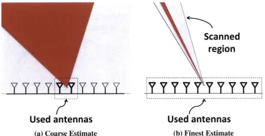
RF-Capture exploits an intrinsic property of antenna arrays, namely: the larger an array is, the narrower its beam, and the finer its spatial resolution. Thus, RF-Capture starts with a small array of few antennas, and uses more antennas only to refine regions that exhibit high reflection power. Fig. 5-2 illustrates this design. The figure uses a ID array for clarity. In the first iteration of the algorithm, RF-Capture computes power using signals from only the two middle antennas of the array, while ignoring the signal from the other antennas. This results in a small aperture, and hence a very wide beam. Using this wide beam, RF-Capture localizes the person to a wide cone as shown by the red region in Fig. 5-2(a). In the next iteration, it incorporates two more antennas in the array. However, in this iteration, it does not need to scan the entire angular space, but rather only the space where it had detected a person in the previous iteration (i.e., the red region in Fig. 5-2(a)). The algorithm proceeds in the same manner until it has incorporated all the antennas in the array and used them to compute the finest possible direction as shown in Fig. 5-2(b).
While the above description uses a ID array for illustration, the same argument applies to 2D arrays. In particular, our 2D array has a T-shape. Thus, in each iteration, we refine the resolution by including an extra antenna from the vertical segment and two antennas from the horizontal segment.
5.2
Coarse-to-Fine Depth Scan
Scanned
region
Used antennas
Used antennas
(a) Coarse Estimate (b) Finest EstimateFigure 5-2: Coarse-to-Fine Angular Scan. We start by using a small number of antennas which gives us a wide beam and coarse angular resolution. Then, we refine our estimate by using more antennas to achieve a narrower beam and finer resolution, but use that beam only to scan regions of interest.
width it uses.
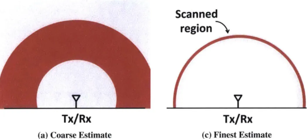
Specifically, it starts by using a small chunk of its bandwidth, which would result in very coarse resolution as shown in Fig. 5-3(a). It then localizes the person to a wide spherical ring. In the following iteration, it uses a larger amount of bandwidth but scans only the spherical ring where it identified the reflector. It proceeds iteratively until it has used all of its bandwidth, as shown in Fig. 5-3(b).
But, what does it mean for us to iteratively increase the bandwidth? Similar to our antenna array iterative approach, we still collect all the data, but process it selectively. Specifically, recall that a fre-quency chirp consists of a signal whose frefre-quency linearly increases over a sweep as shown in Fig. 3-1(b). Whereas all the samples of a sweep collectively cover the entire bandwidth, a subset of those samples covers a subset of the sweep's bandwidth. Similar to iteratively adding more antennas to our processing, RF-Capture iteratively adds chirp samples to achieve finer depth resolution.
5.3
Additional Points
A few points are worth noting:
* RF-Capture performs the above iterative refinement in both FMCW bandwidth and antenna arrays simultaneously as shown in Fig. 5-4.
Scanned
region N
Tx/Rx
Tx/Rx
(a) Coarse Estimate (c) Finest Estimate
Figure 5-3: Coarse-to-Fine Depth Scan. We start by using a small chunk of bandwidth which gives
us coarse depth resolution. Then, we refine our estimate by adding more bandwidth to achieve finer resolution, but use that bandwidth only to scan regions of interest.
Scanned
region
Used antennas
Figure 5-4: Coarse-to-Fine 3D Scan. We can partition and iterate jointly using chirps and antenna arrays.
In any given iteration, we only scan the small region identified by the previous iteration.
which assumes that the signals received by the different antennas are all parallel. To improve the final accuracy of reconstruction and achieve higher focusing capabilities, we use a more complex model in the final iteration of the coarse-to-fine algorithm [48]. Specifically, the power from an (x, y, z) voxel in 3D space can be expressed as a function of the round-trip distances r(nn) (x, y, z) to each
transmit-receive pair (m, n) as follows:1
(5.2)
M N T ,, , _,,z
m=1 n=1 t=1
9 Finally, the coarse-to-fine algorithm (in our current implementation) allows RF-Capture to generate
one 3D snapshot (a 3D frame) of the reflection power every 75ms on Nvidia Quadro K4200 GPU. This represents a speedup of 160, 000x over a standard non-linear projection of Eq. 5.2 which requires on average 200 minutes for rendering a single time snapshot on the same GPU platform. Furthermore, because the switched antenna array has a signal acquisition time of 80ms, the 75 ms rendering time allows RF-Capture to generate a new 3D snapshot within the same signal acquisition period. In addi-tion, it results in a frame rate that is sufficient to continuously track human motion across time. Being able to assume that reflecting bodies smoothly move across a sequence of 3D frames is important for identifying human body parts and tracking them, as we explain in the next section.
'The inverse square law is implicit in S,,,,t and doesn't need to be inverted in the phased array formulation. This is a
standard approximation in antenna arrays since the phase varies by 27 every wavelength, which is a much bigger effect than changes in amplitude. Accounting for the minute variations in amplitude can produce minor sidelobe reductions, but is often negligible [48].
Chapter 6
Motion-based Figure Capture
Now that we have captured 3D snapshots of radio reflections of various human body parts, we need to combine the information across consecutive snapshots to capture the human figure. This process involves the following four steps:
1. Compensation for Depth: Since RF-Capture collects 3D snapshots as the user moves, the subject's
body is at different depths in different snapshots. Therefore, RF-Capture needs to compensate for differences in depth before it can combine information across consecutive snapshots.
2. Compensationfor Swaying: As the person walks, his body naturally sways. To combine information across consecutive snapshots, RF-Capture has to compensate for this swaying and re-align the 3D voxels across snapshots.
3. Body Part Segmentation: Recall that each of the 3D snapshots reveals a small number of body parts.
In the next step, RF-Capture segments each snapshot to extract the body parts visible in it and label them (e.g., head, chest, left arm, left hand, etc.).
4. Skeletal Stitching: In the final step, RF-Capture uses a simple model of the human skeleton to
combine the detected body parts across a few consecutive snapshots and capture the human figure. In what follows, we describe each of these steps in detail. To make the exposition clearer, we describe these steps by applying them to the output of an experiment collected with RF-Capture. In this experiment, the RF-Capture sensor is behind a wall. We ask a user to walk toward the RF-Capture device starting from
a distance of about 3 m from the sensor. The antennas of RF-Capture are positioned at 2 m above the ground, so that reflections from humans arrive along upward directions.
I
-
p ~ I 1. 0) 03 CO 1.5 -0.53 E MA >' 0. nm~etes x-'Ixis Yaetis x-a"xis Yideties ~ .
-(a) Heatmaps obtained when slicing each 3D snapshot at its estimated depth
2 2 2 -1.5 1.5 1.5 . CO . . xis 0etes6 0.9 -1 0 E >O -1 0 0 - . 0.9 -U3 0 3 0. 0.9 V - -.3 0 3
x-axis ?meter0. x-axis meter x-axis Neters) x-axis ?etE
(b) Output after deconvolving the images with the depth-dependent point-spread function
0.6 0.9 rs) 1.8-1 1.5-. 1.2-1 0.0.9.9 0.6 0.3-0 27 24 21 -0.3
baseline for comparisoi
3.1 2.8 2.5 -0.3 x
(c) Kinect skeletal tracking as a
1.5-1.2 S0.9 0.6-0.3 0 -023
A
Figure 6-1: RF-Capture's heatmaps and Kinect skeletal output as a user walks toward the deployed sensors. As the user walks toward the device, RF-Capture captures different parts of his body at different times/distances since its antennas' perspective changes with respect to his various body parts. We rotate the Kinect output by 450 to visualize the angles of the limbs as the user moves.
U
U
3.3 0.3 t8 1 Z 1.2 S0.9 0.6 0.3 0 1.8 1.5 -1.2 S 0.9 -0.6 0.36.1
Compensating for Depth
When imaging with an antenna array, an object looks more blurry as it gets farther away from the array. This is because the beam of an antenna array has the shape of a cone, and hence is wider at larger distances. Since our 3D snapshots are taken as the subject walks towards the array, the subject is at different depths in different snapshots, and hence experiences different levels of blurriness across snapshots. Thus, before we can combine a subject's reflections across RF snapshots, we need to compensate for his change in depth.
To do so, we first need to know the subject's depth in each snapshot. This is easy since our snapshots are three-dimensional by construction -i.e., we know the depth of each voxel that reflects power. Of course, the human body is not flat and hence different body parts exhibit differences in their depth. However, these differences are relatively small. Thus, for our purpose, we take the median depth of the RF reflections in each 3D snapshot, and consider it as the person's depth in that snapshot.
Next, we compensate for depth-related distortion by deconvolving the power in each snapshot with the point spread function caused by the antenna-array beam at that depth. The point spread function is computed directly from the array equation, Eq. 5.2, and the deconvolution is done using the Lucy-Richardson method [37].
Fig. 6-1 illustrates this process. The top row shows different RF snapshots as the person walks towards the antenna array. The snapshots are plotted by slicing the 3D snapshot at the median depth for the reflected signals, and showing the power as a heat map, where red refers to high reflected power and dark blue refers to no reflection. It is clear from this row that reflected bodies look wider and more blurry at larger depths. The second row shows the same snapshots after compensating for depth distortion. These snapshots are less blurry and more focused on the actual reflection points.
6.2
Compensating for Sway
Next, RF-Capture compensates for the user's sway as he walks by using the reflection from his chest as a pivot. Specifically, because the human chest is the largest convex reflector in the human body, it is expected to be the dominant reflector across the various snapshots, enabling us to identify it and use it as a pivot to center the snapshots. From an RF perspective, the human chest is said to have the largest radar cross section [19]. Indeed, the heatmaps in Fig. 6-1(b) show a dominant reflection (dark red) around the
height of the subject's chest (z = 1.4m).
To align the snapshots, we first determine the dominant reflection point in each snapshot. In most snapshots, this would correspond to the human chest. We then perform robust regression on the heights of these maxima across snapshots, and reject the outliers.' This allows us to detect snapshots in which the chest is not the most dominant reflection point and prevent them from affecting our estimate of the chest location. Once we have identified the chest location in each snapshot, we compensate for minor sways of the human body by aligning the points corresponding to the chest across snapshots.
Note that aligning the human body across snapshots makes sense only if the human is walking in the same direction in all of these snapshots. Thus, RF-Capture considers the trajectory of the point with the highest reflection power on the human body, and performs the above alignment only for periods during which the human is walking toward the device without turning around.
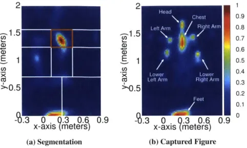
6.3 Body Part Segmentation
After identifying the human chest as a pivot and aligning the consecutive snapshots, we segment the areas around the chest to identify the various human body parts.
Specifically, RF-Capture defines a bounding region centered around the subject's chest. For example, Fig. 6-2(a) shows the rectangle in orange centered around the detected subject's chest. (This is the second image from Fig. 6-1(b) after sway compensation.) Using the chest as a pivot, RF-Capture automatically segments the remainder of the heatmap into 8 regions, each corresponding to a different body part of interest. The first region constitutes the rectangle below the chest, which corresponds to the user's lower torso, while the region above the chest corresponds to the subject's head. The regions to the left and right of the chest correspond to the arms and the hands. Finally, the regions below the torso correspond to the subjects' legs and feet. In our implementation, we specify the width of the torso region to 35 cm, and the height of the upper torso (chest) to 30 cm, while the lower torso is 55 cm. These numbers work well empirically for 15 different adult subjects with different ages, heights, builds, and genders. We envision that exploiting more powerful segmentation and pose estimation algorithms - such as those that employ recognition or probabilistic labeling, e.g., [39, 52, 24] - would capture better human figures. Such 'To perform robust regression, we use MATLAB's default parameters, i.e., bisquare weighting function with a tuning constant of 4.685, and eliminate outliers whose heights are more than two standard deviations away from the mean.
techniques are left for future work.
Once RF-Capture performs this segmentation, the blobs in the heatmaps of Fig. 6-1(b) become more meaningful, and can be automatically assigned body part labels. For example, for the heatmap generated at 2.8m, it can now automatically detect that the blob to the left of the chest is the right arm, and the blob below it is the right hand. On the other hand, the heatmap at 2.2m shows the subject's left hand and his head, but none of his right limbs.
To gain a deeper understanding into the segmented images, we use a Kinect sensor as a baseline. The Kinect is placed in the same room as the moving subject, while the RF-Capture sensor is outside the room. Both devices face the subject. We plot in Fig. 6-1(c) the output of Kinect skeletal tracking that corresponds to the RF snapshots in Fig. 6-1(b). We rotate the Kinect skeletal output by 450 in Fig. 6-1(c) so that we can better visualize the angles of the various limbs. We also perform a coordinate transformation between the RF-Capture's frame of reference and the Kinect frame of reference to account for the difference in location between the two devices. Comparing Kinect's output with that of RF-Capture, we note the following observations:
" RF-Capture can typically capture reflections off the human feet across various distances. This is
be-cause the feet reflect upward in all cases, and hence they reflect toward RF-Capture's antennas.
" It is difficult for RF-Capture to capture reflections from the user's legs. This is because even as the legs move, they deflect the incident RF signals away from the antenna array (toward the ground) rather than reflecting them back to the array since the normal to the surface of the legs stays almost parallel to the ground. (Note that placing the antenna array on the ground instead would enable it to capture a user's legs but would make it more difficult for the array to capture his head and chest reflections.) " The tilt of a subject's arm is an accurate predictor of whether or not RF-Capture can capture its
re-flections. For example, in the third snapshot of Fig. 6-1(c) (i.e., at 2.3m), the subject's right arm (color-coded in pink) is tilted upward; hence, it reflects the incident signal back to RF-Capture's an-tennas allowing it to capture the arm's reflection. Indeed, this matches RF-Capture's corresponding (third) heatmap in Fig. 6-1(b). On the other hand, the subject's left arm (color-coded in red) is tilted upward in the fourth snapshot (i.e., at 2.2m), allowing RF-Capture to capture its reflections in the corresponding heatmap.
2 2 1
Head
Chest 0.9 Left Arm Right Arm 0.8
1.5 -1.5 0.6 aD 1 4 5 10.3
0.E
0. 0.1 Feet0. V3 0 Q. 3 0.6 0.9 -. 3 0 .0.3 .O0.9x-axis (meters) x-axis (meters)
(a) Segmentation (b) Captured Figure
Figure 6-2: Body Part Segmentation and Captured Figure. (a) shows the different regions used to identify body parts, and (b) shows the captured synthesized from 25 time frames.
6.4 Skeletal Stitching
After segmenting the different images into body parts, RF-Capture stitches the various body parts to-gether across multiple snapshots to capture the human figure. We distinguish between two types of body reflectors: rigid parts and deformable parts:
" Rigid Parts, i.e., head and torso: Once RF-Capture compensates for depth and swaying, these
struc-tures do not undergo significant deformations as the subject moves. Hence, RF-Capture sums up each of their regions across the consecutive snapshots (i.e., sum up their reflected power). Doing so pro-vides us with a more complete capture of the user's torso since we collect different reflection points on its surface as the user walks. Furthermore, we found that such a more complete capture of the torso is very helpful in identifying users as we show in 9.
" Deformable parts, i.e., arms andfeet: RF-Capture cannot simply add the segments corresponding to
the human limbs across snapshots. This is because as the human moves, his arms sway back and forth, and adding the different snapshots together results in smearing the entire image and masking the form of the hand. Instead, our approach is to identify the highest-SNR (signal-to-noise ratio) segment for each body part, and select it for the overall human figure. This is because a higher SNR indicates less sensitivity to noise and hence higher reliability.
Finally, to ensure that the resultant figure is smooth, we perform alpha blending [53]. Fig. 6-2(b) shows the result of synthesizing 25 frames together, collected over a span of 2 seconds as the user walks towards our antenna setup. The figure shows that by combining various snapshots across time/distance, RF-Capture is capable of capturing a coarse skeleton of the human body.
Chapter
7
Implementation
7.1 Hardware
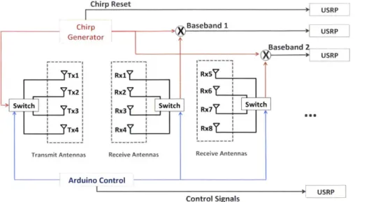
A schematic of RF-Capture's hardware is presented in Fig. 7-1. It has the following components:
" FMCW Chirp Generator: We built an FMCW radio on a printed circuit board (PCB) using
off-the-shelf circuit components, and based on the design in [6]. The resulting radio can be operated from a computer via the USB port. It generates a frequency chirp that repeatedly sweeps the band 5.46
-7.24 GHz every 2.5 ms. The radio has an average power of 70pWatts, which complies with the FCC regulations for consumer electronics in that band [3].
" 2D Antenna array: (shown in Fig. 1-1): The antenna array consists of 16 receive antennas (horizontal section of the T) and 4 transmit antennas (vertical section of the T); the antennas are log-periodic with 6dBi gain. This multiple-transmit multiple-receive architecture is equivalent to a 64-element antenna array. The overall array dimension is 60 cm x 18 cm.1
" Switching Platform: We connect all four transmit antennas to one switch, so that at any point in time,
we transmit the chirp from only one antenna. Similarly, we connect every four receive antennas to one switch and one receive chain. Each receive chain is implemented using a USRP software radio equipped with an LFRX daughterboard. The sampled signals are sent over an Ethernet cable to a PC
'The antenna separation is 4 cm, which is around A. Such separation is standard for UWB arrays since the interference region of grating lobes is filtered out by the bandwidth resolution [50].
Chirp Reset Chirp Generator Tx1' I Tx2 witch T Tx4 Transmit Antennas Arduino Cc Rx1 :Rx2 I Switch Rx3 Rx4 Receive Antennas sUSRP Baseband 1B n2 Baseband USRP :Rx5 :Rx6 Switch Rx7 Rx8 Receive Antennas
Control Signals USRP
Figure 7-1: RF-Capture's Hardware Schematic. The setup consists of a chirp generator connected to a
2D antenna array via a switching platform. The figure shows the Tx chain, and two of the Rx chains.
for processing. This design allows us to use a single transmit chain and only four receive chains for the entire 2D antenna array.
7.2
Software
RF-Capture's algorithms are implemented in software on an Ubuntu 14.04 computer with an i7 processor,
32GB of RAM, and a Nvidia Quadro K4200 GPU. We implement the hardware control and the initial
I/O
processing in the driver code of the USRP. The coarse-to-fine algorithm in 5 is implemented usingCUDA GPU processing to generate reflection snapshots in real-time. In comparison to C processing, the GPU implementation provides a speedup of 36 x.
7.3 Calibration
FMCW and antenna array techniques rely on very accurate phase and frequency measurements. However, various hardware components - including filters, wires, switches, and amplifiers - introduce systematic phase and frequency offsets. To make sure these offsets do not introduce errors for our system, we perform a one-time calibration of the system where we connect each of the Tx and Rx chains over the wire and estimate these offsets. We then invert these offsets in software to eliminate their effect.
Chapter 8
Evaluation Environment
8.1
Participants
To evaluate the performance of RF-Capture we recruited 15 participants. Our subjects are between 21-58 years old (u = 31.4), weigh between 53-93 kg (i = 78.3), and are between 157-187 cm tall (p = 175).
During the experiments, the subjects wore their daily attire, including shirts, hoodies, and jackets with different fabrics. The experiments were conducted over a span of 5 months; the same subject had different clothes in different experiments. These experiments were approved by our IRB.
8.2
Experimental Environment
All experiments are performed with the RF-Capture sensor placed behind the wall as shown in Fig. 1-1.
The experiments are performed in a standard office building; the interior walls are standard double dry walls supported by metal frames. The evaluation environment contains office furniture including desks, chairs, couches, and computers. The antennas are located 2m above the ground level, ensuring that the device is higher than the tallest subject.
8.3
Baseline
We use Kinect for baseline comparison. In our experiments, both Kinect and RF-Capture face the subject, but Kinect is in line-of-sight of the subject, while the RF-Capture sensor is behind the room's wall. We
use Kinect's skeletal output to track the subject, and we perform a coordinate transformation between RF-Capture's frame of reference and Kinect's frame of reference.
Chapter 9
Results
RF-Capture delivers two sets of functions: the ability to capture the human figure through walls, and the ability to identify and track the trajectory of certain body parts through walls. Below, we evaluate both functions in detail.
9.1
Body Part Identification and Tracking
9.1.1
Body Part Identification
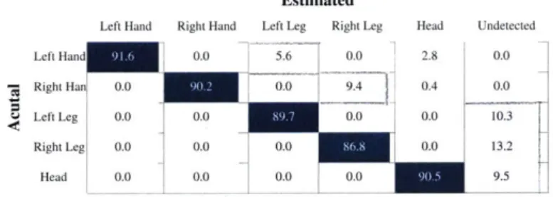
We first evaluate RF-Capture's ability to detect and distinguish between body parts. We run experiments where we ask each of our subjects to walk toward the device (as shown in Fig. 1-1), stop at her chosen distance in front of it, then move one of the following body parts: left arm, right arm, left foot, right foot, and head. The subject can stop at any distance between 3m and 8m away from RF-Capture. We perform
100 such experiments. Throughout these experiments, the subjects performed different movements such
Estimated
Left Hand Right Hand Left Leg Right Leg Head Undetected
Left Hand 00 5.6 0.0 2.8 0.0
Right Ha 0.0 001 4 0.4 0.0
Left Leg 0.0 00 00 0.0 10.3
Right Leg 00 0.0 0.0 0.0 13.2
Head 0.0 0.0 0.0 0.0 9.5
Table 9.1: Confusion Matrix of Body Part Identification. The table shows the classification accuracy of the various body parts at 5 m.
80 100 99.13 97.72 91.60 .S00916 87.44 80 78.53 76.48 a. 60 0 0 -3 4 5 6 7 8
Distance (in meters)
Figure 9-1: Body Part Identification Accuracy with Distance. The figure shows RF-Capture's accuracy in identifying the moving body part as a function of the user's distance to the device.
as: nodding, waving an arm, sliding a leg, or rotating a hand in place.
Classification: We would like to identify which body part the subject moved by mapping it to the
seg-mented 3D snapshots. Hence, in each experiment, we collect the reflection snapshots as the user walks and process them according to the algorithms in 5 and 6 to capture the segmented body parts. Then, we fo-cus on the snapshots after the user stops walking, and moves one limb while standing still. We determine the location of the body part that the user has moved. We compare the identified body part against the user's reported answer for which body part she/he moved after she/he stopped walking and was standing still.
Results: Fig. 9-1 plots the classification accuracy among the above 5 body parts as a function of the user's distance to the RF-Capture sensor. When the user is at 3 m from the antenna setup, the classification accuracy is 99.13%. The accuracy gradually decreases with distance, and reaches 76.48% when the user is 8 m away.
To better understand the source of the errors, we show the confusion matrix in Table 9.1 for the case where one of our subjects stands 5 m away from RF-Capture. The table shows that most errors come from RF-Capture being unable to detect a user's body part motion. This is because while the user did move his limbs, some of these motions may have not altered the reflection surface of the limb to cause a change detectable by the antennas. The other main source of classification errors resulted from misclassifying an upper limb as a lower limb, as opposed to confusing a left limb with a right limb. For example, the right leg and right hand are confused in 5.6% of the experiments, while the right hand and the left hand are never confused. The reason is that our antenna array is wider along the horizontal axis than the vertical axis, as can be seen in Fig. 1-1. Hence, the antenna has a narrower beam (i.e., higher focusing capability)