Publisher’s version / Version de l'éditeur:
ASHRAE Transactions, 99, 1, pp. 1119-1127, 1993
READ THESE TERMS AND CONDITIONS CAREFULLY BEFORE USING THIS WEBSITE. https://nrc-publications.canada.ca/eng/copyright
Vous avez des questions? Nous pouvons vous aider. Pour communiquer directement avec un auteur, consultez la
première page de la revue dans laquelle son article a été publié afin de trouver ses coordonnées. Si vous n’arrivez pas à les repérer, communiquez avec nous à PublicationsArchive-ArchivesPublications@nrc-cnrc.gc.ca.
Questions? Contact the NRC Publications Archive team at
PublicationsArchive-ArchivesPublications@nrc-cnrc.gc.ca. If you wish to email the authors directly, please see the first page of the publication for their contact information.
NRC Publications Archive
Archives des publications du CNRC
This publication could be one of several versions: author’s original, accepted manuscript or the publisher’s version. / La version de cette publication peut être l’une des suivantes : la version prépublication de l’auteur, la version acceptée du manuscrit ou la version de l’éditeur.
Access and use of this website and the material on it are subject to the Terms and Conditions set forth at
Characteristics of diffuser air jets and airflow in the occupied regions
of mechanically ventilated rooms: a literature review
Li, Z. H.; Zhang, J. S.; Zhivov, A. M.; Christianson, L. L.
https://publications-cnrc.canada.ca/fra/droits
L’accès à ce site Web et l’utilisation de son contenu sont assujettis aux conditions présentées dans le site
LISEZ CES CONDITIONS ATTENTIVEMENT AVANT D’UTILISER CE SITE WEB.
NRC Publications Record / Notice d'Archives des publications de CNRC:
https://nrc-publications.canada.ca/eng/view/object/?id=86c1fa7d-3058-40d9-b9d6-a94351e6b43f https://publications-cnrc.canada.ca/fra/voir/objet/?id=86c1fa7d-3058-40d9-b9d6-a94351e6b43fCha ra c t e rist ic s of diffuse r a ir je t s a nd a irflow in t he oc c upie d
re gions of m e c ha nic a lly ve nt ila t e d room s: a lit e ra t ure re vie w
N R C C - 3 6 1 1 7
L i , Z . H . ; Z h a n g , J . S . ; Z h i v o v , A . M . ;
C h r i s t i a n s o n , L . L .
J a n u a r y 1 9 9 3
A version of this document is published in / Une version de ce document se trouve dans:
SHRAE Transactions, 99, (1), ASHRAE Winter Meeting (Chicago, IL, USA,
January-23-93), pp. 1119-1127, 93 (
http://www.nrc-cnrc.gc.ca/irc
The material in this document is covered by the provisions of the Copyright Act, by Canadian laws, policies, regulations and international agreements. Such provisions serve to identify the information source and, in specific instances, to prohibit reproduction of materials without written permission. For more information visit http://laws.justice.gc.ca/en/showtdm/cs/C-42
Les renseignements dans ce document sont protégés par la Loi sur le droit d'auteur, par les lois, les politiques et les règlements du Canada et des accords internationaux. Ces dispositions permettent d'identifier la source de l'information et, dans certains cas, d'interdire la copie de documents sans permission écrite. Pour obtenir de plus amples renseignements : http://lois.justice.gc.ca/fr/showtdm/cs/C-42
CH-93-12-1
CHARACTERISTICS OF DIFFUSER AIR JETS
AND AIRFLOW IN THE OCCUPIED REGIONS
OF MECHANICALLY VENTILATED
ROOMS-A LITERATURE REVIEW
Z.H. Li
J.S. Zhang, Ph.D.
Associate Member ASHRAE
A.M. Zhivov, Ph.D., P.E.
Member ASHRAE
L.L.
Christianson, Ph.D., P.E.
Member ASHRAE
ABSTRACT
In this paper, previous research findings on the charac-teristics of diffuser air jets and airflow in the occupied regions as well as their relationships are reviewed and summarized. Results from differem sources are compared. It was found that it is possible to predict velocity, turbu-lence, and temperature characteristics in the occupied region based on the characteristics of diffuser air jets. However, methods that can quantify the effect of internal obstructions such as office partitions and furniture and the location of heat sources need to be developed.
INTRODUCTION
Proper air distribution is important to achieve satisfac-tory thermal comfort and air quality in the occupied regions of ventilated rooms. Airflow patterns and distributions of velocity. temperature, and turbulence intensity in a ventilat-ed room are primarily determinventilat-ed by the momentum and trajectory of the diffuser air jet and its mixing with and entrainment of room air. Therefore, understanding the characteristics of diffuser air jets and their relations to the airflow conditions in the occupied regions is essential to the selection of diffuser type, sizing, and location. The objec-tive of this paper is to review and summarize the recent research findings in the studies of diffuser air jets and the characteristics of airflow in the occupied region and their relationships and to identify research needs in this area. CLASSIFICATION OF DIFFUSER AIR JETS
Diffuser air jets have different characteristics when they are supplied from different types of diffusers, or under different conditions (initial air temperature, room geometry
and size, supply direction, etc.) . When the temperature of the supplying air jet is equal to the temperature of the air in th·e room, the jet is called an isothermal jet. When there is temperatut:e difference between the incoming air jet and the room air, the jet is called a nonisothermaljet. When the jet is discharging into a large open space (not influenced by walls and ceilings), the jet is called a free jet, whereas when the incoming air jet is attached to a ceiling or wall, it is called an attached jet, ceiling jet (attached to a ceiling), or wall jet (attached to a wall). Furthermore, if the incom-ing air jet is affected by the reverse flow in the room caused by the jet itself, it is called a confined jet.
Depending on the types of diffusers, diffuser air jets can be classified as follows:
1. Compact jets: from grilles, nozzles or other round openings, square openings, or rectangular openings with small aspect ratios. These jets are considered axisymmetric.
2. Linear jets: from slots or rectangular openings with large aspect ratios. These jets have two-dimensional characteristics.
3. Radial jets: from diffusers where the axial flow from a cylindrical chamber is deflected in all 360 degrees. 4. Incomplete radial jets: from grilles having diverging
vanes.
5. Conical jets: from a cone-type or regulated multi-diffuser.
6. Swirling jets: from diffusers that can form vortexes. CHARACTERISTICS OF THE DIFFUSER AIR JETS Isothermal Free Jets
Intensive studies have been performed on velocity decay of isothermal free jets (e.g., Nottage et al. 1952a,
Zhenhai H. Li is a research assistant, Alexander M. Zhivov is a visiting professor, and Leslie L. Christianson is a professor and director of the Bioenvironmental Engineering Research Laboratory, University of Illinois, Urbana-Champaign. Jianshun S. Zhang is a research associate at the Institute for Research in Construction, National Research Council Canada, Ottawa, Ontario.
1952b, 1952c; Tuve 1953; Koestel et al. 1950; Grimitlyn 1970; Shepelev 1961; Baturin 1972; Jackman 1973; Nielsen and Moller 1987). Diffuser air jets can usually be divided into four zones. Zone 1, the initial zone, and zone 2, the transition zone, are usually very short. Zone 3 is of most importance from an engineering point of view. The velocity decay of the centerline of linear jets in this zone can be described by Equation 1 and the velocity decay of compact, incomplete radial, and radial jets can be described by Equation 2: y"
セ@
Yo == K1 (1) y"=
K1.fXO (2) Yo X where V, centerline velocity at x;V0 average velocity at discharge;
H0 effective width of diffuser;
K1 centerline velocity decay constant;
x
distance to the diffuser face on the jet centerline;Ao
effective area of diffuser,Ao
= C4 Ac;Cd discharge coefficient (usually between 0.65 and
0.90);
Ac diffuser free area.
Zone 4 is a terminal zone where the residual velocity decays quickly into large-scale turbulence. Within a few diameters, the axial velocity subsides to the range below 50 fpm. Although this zone was studied by several researchers (Madison and Eliot 1946; Weinhold 1969), its characteris-tics are still not well understood.
Figure 1 shows the velocity decay of four typical jets with diffuser area
Ao
=
0.4 ftl described by Equations 11120
tlCOllf>LETE RADIAL JET
9 13 17 21 2S f X
Velocity decay of the centerline of isothermal jets.
and 2 at the following typical values: for linear jets, K1 = ,
2.2; aspect ratio
=
100; H0=
0.063 ft; for compact jets,K1 = 5.7; for radial jets, K1 = 1.1; for incomplete radial
jets, K1 = 2.0. At the same effective area of the diffuser, the velocity decay described by Equation 1 (linear jet) is
slower than that by Equation 2 at greater values of
x
whenthe K1 values are similar. Because the velocity decay of
Equation 1 varies with the square root of
x,
there is littlechange in velocity decay when increasing
x
at a greatervalue. The velocity decay of a compact jet is much slower than that of radial jets because, within a given distance, compact jets usually experience less shear stress than radial
jets due to their shapes. Since K1 values are directly
proportional to velocity decay and the key factor
determin-ing the velocity decay, accurate measurement of K1 of
diffusers is crucial in designing ventilation systems.
Nonisothermal Free Jets
Velocity Decay and Throw For vertically projected nonisothermal linear jets, it was found that the calculation of velocity decay and throw can be done using the following equations (Shepelev 1961; Grimitlyn 1970):
Y"
セッ@
- == K - K Y. 1 X II 0 (3) K == [1 ± l.Sセa@
( ..!_ )312]113 (4) " K:z 1 ' H 0where K2 = temperature decay constant of the jets. The
" ±"
sign should be positive when the buoyant force is inthe same direction as the initial force, and negative when they are not.
For other vertically projected nonisothermal jets (compact, incomplete radial, and conical), the following equations can be used (Shepelev 1961; Grimitlyn 1970):
Y.,
==K,ffO K
(5)Yo x II
K,.
=
[1 ±2.SK:z Ar
{
___!.__ )"]1/3 (6)K;l
o
.fAo
The velocity decay for sill-mounted grilles can be described by the following equations (Jackman 1971; Regenscheit 1970): V
go
x
.2 = 5.4-+2.15Ar
0( - -5.4) V0x
H0 (7) (8) wherex = distance from grille measured vertically up to the
ceiling and then horizontally across the room from the wall/ceiling comer;
.!1t0
=
temperature of supply air minus temperature of return air;T = mean absolute temperature of air.
The velocity decay rates described in Equations 3, 5, and 7 are compared in Figure 2 at the following conditions:
.!110 = 20°Ri T = 527°R; Y0 = 600 fpm; A0 = 0.4 ft2; for
linear jets, K1 = 1.8,
K,
= 1.7, andH
0 = 0.063; forcompact jets, K1 = 5.3 and K2 = 3.4. All vertical jets are
considered to be directed upward.
From Figure 2 we can see that, although the forms of Equations 3 and 7 for cooled linear jets are different, there is not much difference in the actual velocity decay rates, therefore, either form can be used when calculating the velocity decay. There is much difference, however, in the velocity decay rates between compact jets and linear jets. The velocity decay rate of the linear jet is most rapid. Velocity decay of heated jets is much slower than that of cooled jets because of the gravitational force (Figure 2).
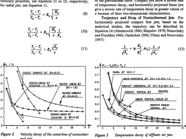
Temperature Decay
Temperature decay of the jetscan be calculated by the following equations (Grimitlyn 1970; Shepelev 1961): For linear jets, horizontally or vertically projected, use Equation 9 or 10, respectively; for compact, incomplete radial, and conical jets, horizontally or vertically projected, use Equation 11 or 12, respectively; for radial jets, use Equation 11.
0.7 0.6 0.5 0.4 0.3 0.2 0.1 T:x-T,
セッ@
= A ;
-T0-T,x
T"- T,.(XO
- - =K. T0 - T, 2x
(9) (10) (11)ヲ
セvセOセv
PセイMMMMMMMMMMMMMMMMMMMMMMMMMMMMMセ@
I£ATED UOR .£T (Kl = 1.8) I£A ltD eot.I'ACTr
(Kt;;;,'i3) 21 2!1 rt X (12) whereT.,
= centerline temperature of the jet at the distance ofx;
T, = return temperature;
T0
=
supply temperature at the diffuser.The curves of temperature decay described by these equations are shown in Figure 3. Again, it is assumed that .!1t0
=
20°R; T = 527°R; Y0=
600 fps; andAo
= 0.4 ftl;for linear jets, K1 = 1.8, K2 = 1.7, and H0 = 0.063; for
compact jets, K1 = 5.3 and K2 = 3.4; for radial jets, K2 =
1. 7. Vertical jets are all considered to be directed upward. It is interesting to note that the temperature decay rates of radial jet and vertically projected linear jets (cooled) are most rapid and they follow almost the same curve, though the temperature decay equations for these two jets are different (Equations 10 and 11). Actually, these two kinds of jets can use the same equation. From Figure 3, it can be seen that vertically projected cooled jets can achieve more rapid temperature decay rates than horizontal jets because of the gravitational force. Compact jets show a slower rate of temperature decay, and horizontally projected linear jets give a slower rate of temperature decay at greater values of
x because of their two-dimensional characteristics.
Trajectory and Drop of Nonisothennal
Jets Forhorizontally projected compact free jets, based on the analytical studies, the trajectory can be described by Equation 14 (Abramovich 1960; Shepelev 1978; Nosovitsky and Posokhin 1966; Omelchuk 1966; Filney and Nosovitsky
QセVWIZ@ (13) 0.8 (r 0.7 . 0.6 K1= !1.3• K2= 3.4
·o.s
0.4 0 • .3 0.2 0.1 0 5 9 17 21 25 ft XFigure 2 Velocity decay of the centerline of nonisother- Figure 3 mal jets.
Temperature decay of diffuser air jets.
where if
z
coefficient, determined by diffuser type, size, etc.; distance below the ceiling at which the maximum velocity in the air jet occurs.
This equation has been verified by experiments (Stein 1953; Koestel 1955; Grimitlyn 1969; Jackman 1970).
For inclined jets, an additional term can be added to the trajectory equation (Shepelev 1961):
X
セ@
(X)3z
= -エァHBセI@
± 1jr2
Aro
-lAo
.fA"o
K1lAo
(14)
where
a0
=
angle of an inclined jet.Experiments were conducted for inclined jets with different types of nozzles and grilles (Grimitlyn et al. 1987) to investigate the coefficients of the trajectory equations. It was found that the mean value of the coefficient if obtained from experimental data was 0.47 ±0.06. The accuracy of these values was suggested to be sufficient for designing the trajectory of inclined ventilation jets at an angle of ao S
±45°.
Effects of Ceilings/Walls
Isothermal ceiling jets were found to attach to the ceiling and flow along it if the initial jet axis was close to the ceiling due to the "Coanda' effect (Nottage et al. 1952a, 1952b, 1952c; Tuve 1953). The spread of the jet in the traversing direction was found to be reduced when the axis of a long jet was too close to the ceiling and parallel to it. The angle of divergence of the jet perpendicular to the wall was slightly less than one-half the angle of a free conical jet (Tuve 1953).
It was found that if an edge of the nozzle was in contact with the plane (the ceiling), so long as the axis of the nozzle formed an angle less than 40
°
to 45°
with the plane, the jet would cling to the plane and spread over it. But if the edge of the jet was shifted away from the plane, air entrainment would occur on all sides of the jets, and the jet did not cling anymore (Baturin 1972). If the jets attached to a ceiling or a wall, K1 became larger than the free jets. The values of K1 were approximately those of the free jets multiplied by 1.4 (Nottage et al. 1952a, 1952b, 1952c; Miller 1990). When the temperature of the attached air jet is lower than the temperature of the ambient air, this jet will remain attached to the ceiling until the downward buoyancy force becomes greater than the upward static pressure ("Coanda" force). At this point, the jet separates from the ceiling and begins curving downward.In designing a cooling ventilation system, careful calculation is needed to keep cold air from dropping directly into the occupied region. The distance to the diffuser face 1122
from the separation point of the jet (X:) was found to be inversely proportional to the Archimedes number at the diffuser face (Equation 16). For slot diffusers, a1 = 1.6 ·
Ao
0.s, b1 =
0.5
(Kirkpatrick et al. 1991), and a1 = 2.5H0 and b1 = 2/3 (Rodahl1977). For several different types of diffusers, a1=
0.63 · (K1A0t·
5
, b1
=
112 (Anderson et al.1991), and a1 = 1.5 · K1 •
Ao
0•5, b1 = 112 (Nielsen andMoller 1987). It was also found that a cold air jet traveling a distance of about 60% of the room length before separat-ing was regarded as sufficient to avoid uncomfortable drafts in the occupied zones.
According to theoretical analysis and experiments (Grimitlyn 1970), the separation distance of jets could be expressed by the following equations. For compact and incomplete radial jets, Equation 16 could be used; for linear and radial jets, Equations 17 and 18 should be used.
xセ@
= al (-l-)6' (15)Ar
0X
6"'
O.SSK1JAo
jセaイ
P@
(16)X
セ@ = 0.4KI4/3 Ho HセaイッIRQS@ (17)X
6 = 0.4$ K1JA'o
jセaイ
P@
(18)It is interesting to note that Equation 17 is similar to Equation 15 where b1 = 2/3 (Rodahl1977), and Equations 16 and 17 are similar to Equation 15 where b1
=
0.5 (Kirkpatrick et al. 1991; Anderson et al. 1991; Nielsen and Moller 1987). It should be pointed out that the constants of the equations are quite different even if they have similar forms.Effect of Confinement
The· influence of the reverse flow in the room on the centerline velocities,
v.<C,
and the temperature differential,lit'", can be expressed by the coefficient
Kc
(Baharev and Troyanovsky 1958; Grimitlyn and Pozin 1973):where
1
llt=
llt -zc z K c (19) (20)at"
= temperature difference between the centerline of the jet and the occupied region.The values of K, are available from gmphs (Grimitlyn and Pozin 1973).
AIRFLOW AND TEMPERATURE CHARACTERISTICS IN OCCUPIED REGIONS
Prediction of Mean Air Velocity in Occupied Region
Jet Momentum Number The jet momentum number
(Jm), jet momentum divided by room volume (Equation 21), of diffusers was reported to be proportional to air velocities at a level one foot above the floor (lj) for high-aspect-ratio slot diffusers and perforated tubes located at the center of the ceiling (Ogilvie and Barber 1989):
Jm
= - -
QiUI (21)gV, where
Q, = incoming volume flow rate; g = gmvity;
u,
= incoming air velocity;v,
= room volume.A good linear relationship between the jet momentum number and the mean air velocity at 1 ft above the floor
(Vp fpm) was confirmed through isothermal experiments in a full-scale room measuring 30 ft X 23 ft X 9 ft (Ogilvie and Barber 1989) (Table 1, Equation 23). It was concluded that a value of Jm of 7.5 X 10⁻⁴ or greater was needed to
maintain the incoming air jet attached to the ceiling and
provide energy for mixing. Experiments by Randall (1980) in a full-scale room measuring 12 ft X 25 ft X 7.5 ft under nonisothermal conditions (temperature difference between -2° and -13°F,jet momentum number 2 to 161 X 10-4) revealed a best-fit curve (expressed in jet momentum number, Jm, Table 1, Equation 24). The difference between Equations 23 and 24 was not significant if Jm was between 4 X 10⁻⁴ and 40 X 10-4 as for Equation 23. But the difference became larger when Jm increased.
Momentum of Jet
The room average velocity, Va,was found to be highly correlated with the jet momentum (M) of the diffuser per unit room volume (Y,) (Miller 1976). Regression was done using Equation 25 (Table 1), based on the 286 tests from 5 different diffusers and 2 different room sizes, 20 X 12 X 9 ft, and 10 X 12 X 9 ft. The constants a and b were found to be dependent on diffusers. The a's varied from 0.604 to 2.02 and the b's
from 0.325 to 0.543. It was suggested that each diffuser use its own regression equation for prediction of room average velocity. It was observed that there was larger uncertainty
when the average room velocity was low.
The mean air velocity in occupied regions (VR, fpm) has been correlated with the momentum of the jet (M, lb,) and room geometry (Table 1, Equations 26 through 29) (Jackman 1970, 1971, 1973). It can be seen that at the same momentum, linear diffusion would result in lower room air velocity.
Jet Initial Velocities The room average velocity, Va,
was found to be linearly varied with the diffuser outlet velocities (Miller and Nevins 1972). This relation was also found to be dependent on the diffuser types and it was
TABLE 1
Equations for Predicting Mean Air Velocity in Occupied Region
I
NoI
EquationsI
ErrorI
ConditionaI
1 V1=21.3+31496Jm (23) R2,..95 4xl0-c< =Jm< =40x10-c, linear
diffusers, perforated tube•, ceiling level (Ogilvie et al. 1989)
2 V1=995xJm·"' (24) R2=0.85 2x10-c < =Jm < = 16lxl0 .. (Randall1980)
3 V セ。HmI「@
-
286 tests from five types of.
セ@ (25) Diffusers(High sidewall diffusen, lighttroffers, cones, slots, and sill grill) (Miller 1976)
4
-
sidewall-grilles; room: 30 x 16 x 10 ft;vNセセ]sQsNoセ@
M (26) grill location: 0.66 ft belowB•H ceiling (Jackman 1970)
5
Jl: セRVQNPH@ セ@
l"
--
sill-grilles; Location: 3 .3 ft high alongII BH (27) the sidewall (Jackman 1971)
6 VR=ll5.6W·· (28)
--
circular ceiling diffuser (Jackman 1973)7 VR=71.5M0·• (29)
-
linear ceiling diffuser (Jackman 1973)8
v.
l uNR=0.026 Two side-wall slots (Fissore 1991)カNセセ]エNャャォv PQ {Q@ +(1 K セI PNウI@ (30)
Ynt2
indicated that room volume would affect the slopes of the regression lines. The mean air velocity in the occupied regions, VR, was correlated to the initial diffuser velocities (Vol> Vm) (Table 1, Equation 30). The test model room measured 8.2 X 14 X 9ft. Slots were located 1.6 ft above the floor on the sidewall. The Reynolds number was from 1,500 to 6,000 and the Archimedes number wa up to 0.03 (Fissore and Liebecq 1990, 1991).
Turbulent Characteristics and Air Distribution
Standard Deviation The standard deviation (SD) of local air velocity fluctuations was found to have a linear correlation with the local mean air velocity,
a,
to a certain extent (Thorshauge 1982; Sandberg 1987). But different studies resulted in different regressions (Hanzawa et al. 1987, results of 20 typically ventilated spaces; Kovanen et al. 1987, field measurement in 24 offices and dwellings). At a level close to the floor, the linear relationship became weaker. Therefore, measurement of both the mean velocity and the standard deviation is usually needed to describe the airflow characteristics more accurately.Energy Distribution and Turbulence Intensity Turbulence intensity has been found to have a significant effect on human thermal comfort (Fanger et al. 1988; Melikov et al. 1987). Turbulence in a ventilated room is generated mainly in the diffuser air jet region due to the interaction of the jet with the room air and with the surface of the ceiling and walls or floor (Zhang et al. 1992). This turbulence is then transported to the occupied region by convective flow, but, at the same time, the turbulence is also damped due to the viscous effect. Therefore, turbulent kinetic energy in the occupied region is usually significantly smaller than in the jet region. However, the turbulence intensity in the occupied region may be high due to the low mean velocity there. D epending on the diffuser types, diffuser velocities, and the relative location between the jet and the occupied region, the average turbulence intensity may vary from 10 % to 40 % (Sandberg 1987; Zhang et al. 1992).
Turbulent kinetic energy within the room covers a wide range of frequencies, usually from 0.05 to 100Hz. But the turbulent kinetic energy of airflow in the occupied region is distributed mainly in the low-frequency range
if
<
10 Hz) (Zhang et al. 1992; Sandberg 1987). Hanzawa et al. (1987) used a linear function to correlate turbulence intensity with the local mean air velocity, but the correlation coefficients were low, ranging from 0.293 to 0.503 (Kovanen et al. 1987).Velocity and Temperature Distribution Over Space The velocities at all measuring points were found to be normally distributed (Thorshauge 1982; Zhang 1991). The standard deviation of velocity distribution over the occupied zone (SDEV) was found to be influenced mainly by the mean air velocity VR, and temperature distribution was found very close to Gaussian distribution (Fissore and
1124
Liebecq 1991). Equations 31 and 32 could be applied when one or two slot diffusers were used, and error could be estimated by a/VR = 0.0053:
SDEV = 0.33 VR (22)
SDEV = 0.30 VR (23) The distribution of temperature differences, llt, between the temperatures in the occupied region (T0, , ) and
the temperature of the jet at the point where it enters the occupied region (T.,) was found to be close to the Gaussian assumption (Grimitlyn et al. 1986). The standard deviation of this distribution H。セ@ was found to be proportional to the temperature difference (flt..) between
T.:
and the mean value of the temperature in the occupied region, qiJ.J=
K, flt". K,was found to be about 0. 8 for compact and conical ceiling jets, and about 1.5 for radial ceiling jets and for compact sidewall jets.
Internal heat load may have a significant effect on the room air distribution (Christianson et al. 1990). The buoyancy effect would cause the jet to fall more quickly and then cause a higher spatial average of mean air velocity in the occupied region. The heat load was also found to contribute to turbulence production and increase turbulent kinetic energy and turbulence intensity in the occupied region (Zhang 1991). Internal obstructions was found to affect the flow pattern and air distribution, as well as the mean air velocities in the occupied region (Zhang 1991).
Discussion
It can be summarized from the above analysis that the key factor affecting the mean air velocity in the occupied region was considered to be the momentum of the incoming jet. Room size and geometry and diffuser types and
loca-tions were also considered to be important, but it seems difficult to quantify all of them. Internal heat load and obstructions may also affect the mean air velocity of the occupied region, but few experimental results of these factors were built into the prediction models. For the existing. models, good prediction results could be expected if the ventilation conditions are close to the test conditions under which these equations were generated. A data base is needed to correlate the mean air velocity in the occupied regions with jet momentum, etc., under various ventilation conditions. With this data base, it will be possible to predict the mean air velocity in the occupied regions at the design stage.
Since turbulence in the occupied region is transported mainly from the jet region where it is generated, a relation-ship exists between the turbulence in the occupied region and the flow characteristics of the diffuser air jets, room geometry, and internal obstructions. Therefore, it is possible to develop a method that can use the jet character-istics to predict the turbulence intensity as well as the mean velocity and temperature in the occupied regions.
CONCLUSIONS
1. It is possible to predict the velocity and temperature characteristics of the jets at the point where they enter the occupied region using the current jet theory. However, further research is needed to relate the jet characteristics to the airflow and temperature in the occupied region. It is especially important to quantify the effects of room geometry, obstructions, and room partitions in order to have a better understanding of room air motion and predict the thermal comfort condi-tions in occupied regions during the design stage.
2. The mean air velocity in the occupied region has been
correlated with the jet momentum, jet momentum number, and room sizes. The effects of diffuser types and location, internal heat loads, and obstructions need to be studied and built into prediction models. A data base built on various ventilation systems and room geometries will help to produce consistent prediction models.
3. A relationship exists between the airflow turbulence in the occupied region and the characteristics of diffuser air jets. Research is needed to develop a method that can predict the turbulence intensity as well as mean velocity and temperature in the occupied regions.
REFERENCES
Abramovich, G.N. 1960. The theory of turbulent jets.
Moscow: Fizmatgiz.
Anderson, R., V. Hassani, A. Kirkpatrick, K. Knapp-miller, and D. Hittle. 1991. Experimental and
compu-tational visualization of cold air ceiling jets. ASHRAE
Journal 33(5).
ASHRAE. 1989. 1989 ASHRAE handbook-Fundamentals,
chapter 31. Atlanta: American Society of Heating, Refrigerating and Air-Conditioning Engineers, Inc.
Baharev, V., and V. Troyanovsky. 1958. Principles of
heating and ventilating systems design with concentrat-ed air supply. Moscow: Profizdat.
Baturin, V. V. 1972. Fundamentals of industrial ventilation,
3d enlarged ed. New York: Pergamon Press.
Christianson, L.L. J.S. Zhang, and G.L. Riskowski. 1990.
Similitude modeling of non-isothermal flow in rooms
with internal obstruction. Room Vent '90, Oslo,
Nor-way, June 13-15.
Fanger, P.O., A.K. Melikov, H. Hanzawa, and J. Ring.
1988. Air turbulence and sensation of draught. Energy
and Buildings 12: 21-39.
Filney, M., and A. Nosovitsky. 1967. Air supply by free
compact jets. Proceedings of High Schools
"Con-struction and Architecture" #2.
Fissore, A.A., and G.A. Liebecq. 1990. Experimental study of air jets pathways in large slot ventilated
spaces. Room Velll '90. Engineering Aero- and
Ther-modynamics of Ventilated Rooms. Second International Conference, Oslo. Norway, June 13-15.
ASH RAE Transactions: Symposia
Fissore, A.A., and G.A. Liebecq. ·1991. A simple empiri-cal model for predicting velocity distributions and
comfort in a large slot-ventilated space. ASHRAE
Transactions 97(2).
Glauert, M.B. 1956. The wall jet. Journal of Fluid
Me-chanics 1: 625.
Grimitlyn, M. 1969. Modeling and designing of air
distri-bution devices. In Filtration of Industrial Exhausts and
Problems of Air Distribution. Leningrad: Occupational Safety Institute under the AUCCTU.
Grimitlyn, M. 1970. Zurluftverteilung in Raumen.
Luft-und Kaltetechnik 5.
Grimitlyn, M. 1982. Air distribution in enclosed spaces.
Moscow: Stroiisdat.
Grimitlyn, M., and G. Pozin. 1973. Determination of
parameters for the jet in a confined space following
blocked- or through flow pattern. Proceedings of
Research Institutes for Labor Protection VTsSPS 91. Grimitlyn, M., A. Zhivov, and S. Kondrashov. 1986.
Specific air distribution in the premises with increased requirements for the uniformity of temperature field in
the occupation zone. In Intensification of Production
and Increased Application of Artificial Cold. Theses of conference. Leningrad: Technological Institute of Refrigeration Industry.
Grimitlyn, M., A. Zhivov, andY. Kelina. 1987.
Experi-mental studies of non-isothermal free jet. Occupational
Safety Problems and their Solutions-Collected Papers of the Occupational Safety Institutes under the A UCCTU. Moscow: Profizdat.
Hanzawa, H., A.K. Melikov, and P.O. Fanger. 1987. Airflow characteristics in the occupied zone of
ventilat-ed spaces. ASHRAE Transactions 93(1): 524.
Jackman, P.J. 1970. Air movement in rooms with side-wall
· mounted grilles. Heating and Ventilating Research
Association. Laboratory Report No. 65.
Jackman, P.J. 1971. Air movement in rooms with siii-mounted grilles. Heating and Ventilating Research Association. Laboratory Report No. 71.
Jackman, P.J. 1973. Air movement in rooms with ceiling-mounted diffusers. Heating and Ventilating Research Association. Laboratory Report No. 81.
Kirkpatrick, A., T. Malmstrom, K. Knappmiller, D. Hittle, P. Miller, V. Hassani, and R. Anderson. 1991. Use of
low temperature air for cooling of buildings.
Proceed-ings 1991 Building Simulation Conference.
Koestel, A., P. Herman, and G. Tuve. 1950. Research report 1404-Comparative study of ventilating jets
from various types of outlets. ASHVE Transactions 56:
459.
Kovanen, K., 0. Seppanen, K. Siren, and A. Majanen. 1987. Air velocity, turbulence intensity and fluctuation frequency in ventilated spaces. Room Vent '87, Stock-holm, Sweden, June 10-12.
Madison, R.D., and W.R. Eliot. 1946. Throw of air from
slots and jets. Heating, Piping, and Air Conditioning
11: 108.
Melikov, A.K., H. Hanzawa, and P.O. Fanger. 1987. Mean velocity and turbulence intensity in ventilated and unventilated spaces. Room Vent '87, Stockholm, Sweden, June 10-12.
Miller, P.L. 1976. Final report to U.S. Army Construction Engineering Research Laboratory. Mechanical Engi-neering Department, Kansas State University. Miller, P.L. 1990. Diffuser selection for cold air
distribu-tion system design practices guide. Research report to Electric Power Research ·Institute. Mechanical Engi-neering Department, Kansas State University.
Miller, P.L., and R.G. Nevins. 1972. An analysis of the p.erfonnance of room air distribution systems. ASHRAE Transactions.
Nielsen, P.V., and A.T. Moller. 1987. Measurement on buoyant wall jet flows in air conditioned rooms. Room Vent '87, Stockholm, Sweden.
Nosovitsky, A., and V. Posokhin. 1966. Inclined fountains of heated and chilled air, created by non-isothermal jets supply. Heat, Gas Supply and Ventilation. Kiev: Budivelnik.
Nottage, H.B., J.G. Slaby, and W.P. Gojsza. 1952a. ASHVE Research Report No. 1458-0utlet turbulence intensity as a factor in isothermal-jet flow. ASHVE Transactions 58: 343.
Nottage, H.B., J.G. Slaby, and W.P. Gojsza. 1952. A smoke-filament technique for experimental research in room air distribution. ASHVE Transactions 58: 399. Nottage, H.B., J.G. Slaby, and W.P. Gojsza. 1952.
ASHVE Research Report No. 1459-Exploration of a chilled jet. ASHVE Transactions 58: 357.
Ogilvie, J.R., and E.M. Barber. 1989. Jet momentum number: An index of air velocity at floor level. Build-ing Systems: Room Air and Air Contaminant Distribu-tion, L.L. Christianson, ed. Atlanta: American Society of Heating, Refrigerating and Air-Conditioning Engi-neers, Inc.
Omelchuk, V. 1966. Laws of non-isothermal jet develop-ment, banded by gravity forces. Journal of Water Supply and Sanitary Technique 2.
Randall, J.M. 1980. Selection of ventilation systems and penning layouts for piggeries based on the cooling effects of air speed and temperature. J. Agric. Engr. Res. 25: 169-187.
Regenscheit, B. 1970. Die Archimedes-Zahi-Kenzah zur . beurteilung von Raumstromungen. Gesundhheits Jngenieur 91(6).
Rodahl, E. 1977. The point of separation for cold jets flowing along the ceiling. CLIMA 2000. Belgrade, Yugoslavia.
Sandberg, M. 1987. Velocity characteristics in mechan-ically ventilated office rooms. Room Vent '87, Stock-holm.
Shepelev, I. 1961. Air supply ventilation jets and air fountains. In Proceedings of the Academy of Construc-tion and Architecture of the USSR 4. . Shepelev, I. 1978. Air dynamics of air flows in rooms.
Moscow: Stroyizdat. 1126
Stein, M. 1953. Studies on air jets. Journal of the Institute of Heating and Ventilating Engineers 21.
Thorshauge, J. 1982. Air velocity fluctuations in the occupied zone of ventilated space. ASHRAE Transac-tions 88(2): 753.
Tuve, G.L. 1953. ASHVE Research Report No. 1476-Air velocity in ventilating jets. ASHVE Transactions 59: 261.
Weinhold,
K., R.
Dannecker, and U. Schwiegk. 1969. Uber Auslengungsverfahren von Liiftungsdecken. Luft-und KlllretecJmick 2: 78-84.Zhang, J.S. 1991. A fundamental study of two dimensional room ventilation flows under isothermal and non-isothermal conditions. Unpublished Ph.D. thesis, University of Illinois at Urbana-Champaign.
Zhang, J.S., G.J. Wu, and L.L. Christianson. 1992. Full-scale experimental results on the mean and turbulent characteristics of ventilation flows. ASHRAE Transac-tions 98(2).
DISCUSSION
Avnit Singh, Deparlment of Mechanical Engineering,
University of South Carolina, Columbia: KoestePs work was elaborated upon by Dr. Azer in the area of cooled jets. Why were they not referred to? Those equations seem to be
different from the equations shown.
Zbenhai Li: Koestel's work was referred to in this paper, although the forms of the equations may look different because we put the equations from different sources into one consistent form. Studies from different sources may only be good for certain test conditions. We combined and compared the results from different sources in order to generate consistent analysis, as shown in the figures of this paper.
Kenneth Elovitz, Engineer, Energy Economics,
Inc.,
Foxboro, MA: One early slide showed the velocity of a vertically upward projected cooling jet leveling off at about 20% of initial velocity. This implies that a jet of air could reach the moon at some steady velocity. How can that be? Li: These equations can only be applied at certain ventila-tion condiventila-tions and, of course, within a certain limit of length.
Albert
J.
Heber, Associate Professor, Department ofAgricultural Engineering,
Kamas
State University,Manhattan:
Should the variablex
in the jet throw equationsbe measured from the' diffuser face or the location of the vena contracta? It seems that it should be defined as the distance from the vena contracta in the purest sense since
the maximum momentum of the jet occurs at that point.
Would you please comment on that?
Ll:
F'or some
.·typesof
.diffosem
tho
vema contracta
ia
the
diffuser
face.For the
セ@win
エィセエ@veDa ccmtracta
is
uoi
the
ctiff\asei:
r.,
dro
tOtal iUStallQO·
X •
1:Hs セ@by
X
+
Xo•
:Since
zone
3
is the.one of most interest.
to
us,
where X is セ@
pater
tltaQJG,
セ@is
セャ・」エ・、@far
simplicity.