HAL Id: hal-02186370
https://hal.univ-lorraine.fr/hal-02186370
Submitted on 17 Jul 2019
HAL is a multi-disciplinary open access
archive for the deposit and dissemination of
sci-entific research documents, whether they are
pub-lished or not. The documents may come from
teaching and research institutions in France or
abroad, or from public or private research centers.
L’archive ouverte pluridisciplinaire HAL, est
destinée au dépôt et à la diffusion de documents
scientifiques de niveau recherche, publiés ou non,
émanant des établissements d’enseignement et de
recherche français ou étrangers, des laboratoires
publics ou privés.
Sizing Supercapacitor for Direct Hybridization with
Polymer Electrolyte Membrane Fuel Cell
Divyesh Arora, Melika Hinaje, Caroline Bonnet, Stephane Raël, François
Lapicque
To cite this version:
Divyesh Arora, Melika Hinaje, Caroline Bonnet, Stephane Raël, François Lapicque.
Siz-ing Supercapacitor for Direct Hybridization with Polymer Electrolyte Membrane Fuel Cell.
2018 IEEE Vehicle Power and Propulsion Conference (VPPC), Aug 2018, Chicago, France.
�10.1109/VPPC.2018.8605027�. �hal-02186370�
XXX-X-XXXX-XXXX-X/XX/$XX.00 ©20XX IEEE
Sizing supercapacitor for direct hybridization with
polymer electrolyte membrane fuel cell
Divyesh Arora GREEN and LRGP University of Lorraine and CNRS
Nancy, France [email protected] Melika Hinaje GREEN University of Lorraine Nancy, France [email protected] Caroline Bonnet LRGP
University of Lorraine and CNRS Nancy, France [email protected] Stéphane Raël GREEN University of Lorraine Nancy, France [email protected] François Lapicque LRGP
University of Lorraine and CNRS Nancy, France
Abstract—An efficient solution to accommodate fuel cell (FC)
systems to the dynamic loads met in transport applications consists in hybridizing the FC with a storage device, such as batteries or supercapacitors. Among all possible configurations, direct hybridization with supercapacitors offers substantial advantages in terms of mass, volume, reliability, efficiency and cost. The present article investigates the influence of supercapacitor sizing on FC efficiency. For this purpose, a FC electrical model based on mass and charge transport equations, associated with a supercapacitor electrical model including porosity effects, are used to compute the hybrid source responses to an urban dynamic load profile. Simulated results, which demonstrate how increasing supercapacitor can enhance FC efficiency, are validated by experimental tests carried out on a 100 cm2 single FC fed with dry hydrogen and humidified air.
Keywords—PEM fuel cell modeling, supercapacitor modeling, direct hybridization, energy efficiency, dynamic load cycling.
I. INTRODUCTION
Fuel cells (FC) are one of the promising technologies in transport applications [1]. Compared to batteries, they present higher energy densities, up to several kWh.kg-1, so greater autonomy than battery electric vehicles, and they are not subjected to one of the main issues of those vehicles, i.e. fast charging. However, their power densities in transient regime remain limited by the substantial response times of their ancillaries (such as flow controllers, air compressor). As a consequence, FC are not well suited to the rough current and power profiles met in transport applications. In particular, load peaks can induce transient gas starvation which may cause irreversible degradations [2].
A widespread solution to accommodate FC systems to dynamic loads consists in hybridizing the FC with a power source, such as lithium-ion battery of power type, or supercapacitor (SCAP). Such an association enables to submit the FC only to slow regimes transients, by managing power peaks through the storage device. Furthermore, one can take advantage of hybridization for FC power downsizing, and for regenerative breaking. Many examples of hybridized FC
systems, most often dedicated to electric vehicle applications, as in [3-6], but also to tramway applications, as in [7] and [8], and even to aircraft applications [9], can be found in the literature. Generally, these systems involve batteries and/or supercapacitors as storage device, and a DC/DC power electronic converter to connect the storage device, whether to the FC, or to a DC link. This way to proceed clearly offers a high degree of freedom for energy control and management within the hybrid source (HS). However, using an interface converter for coupling the storage device to the fuel cell leads to an increase in weight, volume, and cost, in addition to higher risk of failure and energy losses.
These drawbacks can be avoided by direct (or passive) hybridization, which simply consists in connecting directly the storage device to the fuel cell. For this purpose, electric double layer supercapacitors are generally used because of their adaptable voltage, but some works, e.g. [9], also deal with FC/batteries association without converter. Another major advantage provided by direct hybridization, compared to active hybridization, is production of FC current nearly free of high frequency (HF) and low frequency (LF) harmonics. The first ones are generated by the DC/DC converter generally involved in FC systems to boost the FC voltage to the required level, and the second ones can be generated by the DC/AC converter which supplies AC motors in transport applications. In both cases, direct hybridization naturally enables to supply current harmonics by the storage device, its impedance being by principle significantly lower than the FC one.
The present article deals with direct hybridization of a single polymer electrolyte membrane fuel cell (PEMFC) with a supercapacitive device. Some previous works have already investigated this configuration. In [10], a specific study is conducted upon current sharing during load steps. In particular, this article puts to the fore the importance of all series resistances in short time. In [11], theoretical and experimental investigations demonstrate that a single PEMFC can operate as a perfect current source, controlled by the hydrogen flow rate. An interesting consequence of this property is that no pre-charge device is required for such a hybridization
configuration. At last, recent experimental results about long-period runs under cyclic operation show that hybridizing directly a single PEMFC with supercapacitor does not lead to further ageing of the fuel cell components [12].
In this study, our purpose is to investigate, in terms of energy features, the direct hybridization of a single PEMFC and a supercapacitive device. More particularly, this work focuses on the effects of the storage device capacitance on FC current and voltage responses, and on electrical losses, produced energy, hydrogen consumption, and FC efficiency. Simulation has been employed for this purpose. Fuel cell and supercapacitor models are presented in section II. Section III details and discusses simulation results, obtained by submitting either the fuel cell alone, or FC/SCAP direct hybrid source with various values for the storage device capacitance, to a current profile based on the European Harmonized Fuel Cell Dynamic Load Cycle (FC-DLC). Some experimental results are presented in section IV, and compared to the simulated ones.
II. MODELING OF PEMFC/SUPERCAPACITORS DIRECT
HYBRIDIZATION
A. Single PEM Fuel Cell Model
The core of a fuel cell is a system involving multi-physics coupling phenomena: mass transport in electrodes and membrane, charges transport in the membrane, and electrochemical kinetics at reactive sites. Fuel cell performance also depends on distribution of reactive gases and thermal management. Numerous mathematical models, as those presented in [13], [14] and [15], have been developed to describe these phenomena locally, through partial differential equations (PDE) involving space and times. These models are accurate but unsuitable for a system approach. That is the reason why some electrical circuit models have been established, such as in [16] and [17]. However, most of the circuit models are of "small signals" type, which means that they are strictly valid close to the considered operating point, because of the non-linearity of the fuel cell.
For investigating and analyzing direct hybridization of PEMFC and supercapacitors, this work relies upon a previous PEMFC electrical model based on a 1D analog representation of mass transport phenomena in gas diffusion layers (GDL) and membrane [18]. Although it can be considered of circuit type, this model is fundamentally based on transport partial differential equations (PDE). As a result, it naturally includes large signal description, fuel cell non-linearity, and influence of operating conditions (temperature, gas flow rates, pressure, and humidity) on fuel cell voltage. Furthermore, the use of electrical analogy for the formulation of transport PDE enables the implementation of the model in simulation software Saber® commonly used in electrical engineering to design systems.
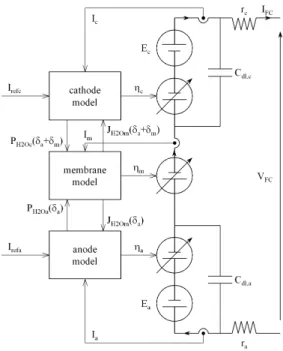
Assumptions and simplifications in the present model are: 1) constant and homogeneous cell temperature, 2) single phase gas mixtures, 3) one-dimensional mass and charge transports, 4) gas-tight and homogeneous membrane, 5) catalyst layers treated as interfaces. Fig. 1 depicts the structure of the PEMFC model. It consists in two sub-models coupled to each other.
Fig. 1. PEM fuel cell model.
The first one (on left) computes mass transport in GDL and membrane. It calculates gas flows and partial pressures in GDL, water content and water flow in the membrane, as a function of operating condition at gas inlets (gas flow rates, pressures, and humidity) and cell temperature. Outputs are electrochemical overvoltages at membrane/electrode interfaces, and voltage drop across the membrane. The second one (on right) is a standard electrical scheme, computing the fuel cell voltage versus fuel cell current, equilibrium potentials and overvoltages, and feeding back the transport sub-model with fuel cell current and faradic currents at electrodes. One will find in previous work [18] all details of the model: basic equations, parametric laws, analog formulation, implementation in Saber® software, experimental validation.
Gas flow rates at electrode inlets are represented by two signals, Irefa and Irefc, according to:
⋅ ⋅ ⋅ = ⋅ ⋅ = c refc air a refa H V F I d V F I d ζ ζ 21 . 0 1 4 2 0 0 2 (1)
where V0 is the molar volume, and ζa and ζc are the stoichiometric coefficients at anode and cathode, respectively. Both signals Irefa and Irefc are calculated from a reference signal
Iref which represents the fuel cell limit current according to
Faraday's law, as follows:
( )
( )
( )
( )
( )
( )
⋅ = ⋅ = s I s f s I s I s f s I ref c refc ref a refa (2)s being the Laplace variable, and fa and fc being the transfer
functions representing the time responses of anode and cathode gas flow regulators, respectively.
B. Supercapacitor Model
Supercapacitors are electrical storage devices that offer high power density compared to conventional batteries. Their energy storage principle is based on electric double layer, which is of electrostatic nature. Therefore, they are able to store or yield a large energy amount within a short period of time, and their lifetime is known to be quite long, about one million full charge-discharge cycles. Many models have been established to describe and explain the capability of supercapacitors. At low frequencies, simple RC models are often good enough to describe with a reasonable accuracy the supercapacitor electrical behavior [19]. Nevertheless, high accuracy at high frequencies is also needed here, in order to evaluate correctly power sharing between PEMFC and supercapacitors, at a step load current. Therefore, a supercapacitor electrical model has been used taking into account porosity effects, typically by means of a RC transmission line [19] [20].
Fig. 2 presents the electrical scheme of the supercapacitor model. It is composed of a series resistance RHF, and a
capacitive transmission line characterized by two parameters, the total line capacitance C, and the total line resistance R. For sake of simplicity, neither the capacitance non-linearity nor the charge redistribution phenomenon (which takes place in very long time) are taken into account. Model implementation in Saber® software is achieved, by means of the line discretization in n = 50 elements. Manufacturer data usually give the rated capacitance of the device, which can be considered as the line capacitance C, the high frequency resistance RHF, and the low
frequency resistance RBF. As demonstrated in [20], the line
total resistance R can be deduced from RHF and RBF as follows:
(
RBF RHF)
R= 3⋅ − (3)
C. Hybrid Source Model
Direct hybridization of a PEMFC and a supercapacitor simply consists in paralleling these two devices. In such a case, it is crucial to consider the resistance of the connection, as far as this parameter greatly influences the power sharing in short time [10], and time constant of the filtering effect introduced by supercapacitors.
Fig. 3 depicts the electrical scheme of the hybrid source. It is composed of the two models previously described, connected in parallel through a resistive element standing for voltage drops across wires and contacts that achieve the direct electrical link between the fuel cell and the supercapacitive device. This element is characterized by an ohmic resistance
RW.
Fig. 2. Supercapacitor model.
Fig. 3. Hybrid source model.
III. SIMULATION RESULTS AND DISCUSSION
In this section, simulation allows investigation on the effects of the storage device capacitance on fuel cell and supercapacitor contributions to energy production, and on the efficiency of the hybrid source, in particular in comparison with the case for which the fuel cell is not hybridized. For this purpose, we have submitted either the fuel cell alone, or the hybrid source, to a current profile based on the European Harmonized Fuel Cell Dynamic Load Cycle (FC-DLC). This operating cycle, which is 20-minute long, is a standard for the energy demand in urban transport [21]. Focus is particularly put on energy features, e.g. FC RMS current IFCRMS (which
represents an important part of losses in both fuel cell and connections), FC mean power PFCMEAN, hydrogen consumption,
and FC yield.
A. Model Parameters
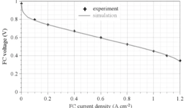
PEMFC model parameters are extracted either from literature (parametric laws used for gas and water diffusion coefficients, electro-osmotic drag in the membrane, water sorption at membrane/electrode interfaces, and membrane ionic conductivity are given in [18]), or from experimental setup (see section IV.a) and characterization tests (in particular for GDL and membranes thicknesses, additional ohmic resistances, cathode exchange current density). Fig. 4 compares the experimental polarization curve of the 100 cm2 single PEMFC installed on our test bench, and the associated simulated results. The single fuel cell was fed with dry hydrogen and humidified air (relative humidity: 57 %) at pressure close to ambient, with hydrogen and air stoichiometric factors maintained at 1.2 and 2.5 respectively. Cell temperature was set to 55 °C. Within the current density range of the current profile used in this study, i.e. [0 A.cm-2 , 1 A.cm-2], the gap between experiment and modeling does not exceed 8 mV.
Fig. 4. Polarization curve of the single PEMFC under test. In black: experience, in grey: simulation. Cell temperature: 55 °C. Gas supply conditions: ambient pressure, dry hydrogen, HRC = 57%, ζa = 1.2, ζc = 2.5.
For supercapacitor model parameters, typical data of 3000 F power devices (RHF = 0.5 mΩ, RBF = 1 mΩ) have been
used. For other values of rated capacitance, RHF and RBF are
calculated according to an inversely proportional dependence on capacitance, as far as the main sizing factor of supercapacitors is the active surface.
Finally, the internal connection resistance of the hybrid source is simply measured on our test bench, by averaging the quantity
(
VFC −VSC)
/IFC over a complete dynamic load cycle,carried out with a 3000 F supercapacitor. The value obtained for RW is 3.5 mΩ.
B. Operating conditions used for simulation
FC temperature is set to 55 °C. The 100 cm2 cell is supplied with dry hydrogen and humidified air (HRc = 57 %) at ambient
pressure, with the following stoichiometric factors: ζa = 1.2 and ζc = 2.5. As schemed in Fig. 1, flow regulator transient responses are estimated by linear transfer functions. Devices employed in our test bench can be modeled, for the anode one by a first order with a response time of 1 s, for the cathode one by a second order with a response time of 5 s.
Flow rates, defined by (1) and (2), are most often computed as a proportional function of FC current (IREF = IFC), according
to Faraday's law and stoichiometric factors. However, as usually done in FC-DLC operation for safety reasons, a minimum level IREFMIN is considered for IREF, and therefore for
gas flow rates. In our study, IREFMIN is set to 20 A, which more
generally corresponds to 0.2 A.cm-2 for the gas supply safety level. Furthermore, in the non-hybridized configuration (FC alone), for which fuel cell current is identical to load current, gas flow rates are anticipated a few seconds before each positive current step, in order to avoid starvation during flow regulator transient. An anticipation time of 5 s, corresponding to time response of the cathode flow regulator, is used.
The FC-DLC current profile imposed to either the PEMFC alone, or the hybrid source, is presented in Fig. 5. Its minimum, maximum, mean and RMS values, over a 20-minute cycle, are 0 A, 100 A, 27.7 A, and 38.3 A, respectively.
C. Current and Voltage Waveforms vs Supercapacitor Size
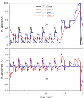
Fig. 5 presents current waveforms over a FC-DLC cycle, obtained in steady state for different values of the storage device capacitance: fuel cell alone (in black), C = 100 F (in grey), C = 1000 F (in blue), and C = 9000 F (in red). "Steady state" means here that the hybrid source response to the current profile is periodic. This has been checked by computing
ISCMEAN over a complete cycle (ISCMEAN is equal to 0 A at steady
state), and is generally reached after the first cycle.
Evidently, increasing the capacitance enhances the smoothing effect introduced by supercapacitor on FC current. This can obviously be observed in long time, through a slower variation of IFC and a significant reduction in IFC amplitude
(100 A if the fuel cell is used alone, 73 A if it is hybridized with a 9000 F supercapacitor). As a consequence, one can predict the reduction in IFCRMS and associated losses in FC and
hybrid source internal connections, along with the capacitance increase.
Fig. 5. Simulated current waveforms over a FC-DLC cycle. (a): FC current, (b): supercapacitor current. Black curve: FC alone, grey curves: C = 100 F, blue curves: C = 1000 F, red curves: C = 9000 F.
Another major outcome is the intensification of the minimum FC current along the cycle (FC alone: IFCMIN = 0 A,
C = 9000 F: IFCMIN = 12 A), from which a more efficient use of
hydrogen can be expected, through the lowering of H2 over-consumption induced by the safety level IREFMIN. The
supercapacitor smoothing effect can also be put to the fore in short time, with higher contribution of supercapacitor to load current steps: below 28 % at C = 100 F, about 81 % at
C = 1000 F, and up to 97 % at C = 9000 F. In this latter case,
nearly no discontinuity is observed on FC current.
Fig. 6 shows simulated FC voltage responses over a FC-DLC cycle, obtained in steady state for different values of the capacitance C. As previously, these curves highlight the smoothing effect introduced by supercapacitor. Indeed, enlarging the storage device capacitance leads to a slower VFC
evolution, and to reduction in VFC amplitude (FC alone: ΔVFC = 520 mV, C = 9000 F: ΔVFC = 280 mV). In short time, it
can also be observed that the sharp VFC variations that occur at
load current steps when FC is used alone, are replaced by milder voltage transitions under strong hybridization, as a consequence of slow FC current transients.
Fig. 6. Simulated FC voltage waveforms over a FC-DLC cycle. Black curve: FC alone, grey curves: C = 100 F, blue curves: C = 1000 F, red curves:
Furthermore, one can determine on FC voltage responses the minimum value CMIN for the storage device size, above
which no gas flow rate anticipation is required (no risk of starvation during positive load current steps). In the case treated here, CMIN is about 200 F. If the minimum level IREFMIN
is set to 5 A, which corresponds to the measurement range of the hydrogen flow controller used in our test bench, a 600 F supercapacitor is required to avoid starvation.
D. Energy Features vs Supercapacitor Size
As previously mentioned, the FC RMS current, computed in steady state over a complete cycle as follows:
( )
1/2 0 2 1 ⋅ ⋅ =
T FC FCRMS I t dt T I (4)T being the FC-DLC period, is an important energy feature, as far as it is of major contribution in FC electrical losses. From this point of view, the smoothing effect provided by direct hybridization on fuel cell current leads to reduce IFC variations
along the cycle, and therefore results in a substantial decrease of IFCRMS. This effect is depicted in Fig. 7, which presents the
evolution of the ratio IFCRMS/IFCMEAN, as a function of the
storage device capacitance.
Then, the first positive consequence of IFC smoothing is a
decrease in HS electrical losses. This decrease reaches 26 % at
C = 9000 F for HS internal connections. In the present case, it
represents a significant gain (about 11 %) for the energy supplied by the hybrid source, but it must be noticed here that this interesting result is essentially due to the fact that our study is led on a single PEMFC. Should a fuel cell stack be now considered, the gain in HS supplied energy provided by the decreases of electrical losses within connections would be obviously mitigated.
On the contrary, benefits provided by the decrease in FC electrical losses due to supercapacitor smoothing effect can be fully extended to fuel cell stacks. Fig. 7 presents this decrease as a function of the storage device capacitance, relatively to the FC alone operation. It reaches 14 % at C = 9000 F, which represents a gain of 8 % in the electrical energy supplied by the PEMFC.
Fig. 7. IFCRMS/IFCMEAN ratio (in black) and decrease in FC electrical losses (in
grey, reference: FC alone operation vs storage device capacitance.
The second and main positive consequence of IFC
smoothing is a reduced impact of flow rate safety levels on hydrogen consumption. Strictly according to Faraday's law (ζa = 1, IREFMIN = 0 A, no flow rate anticipation before positive
current steps) applied to the value of mean load current (27.7 A for the considered FC-DLC), the minimum H2 consumption is equal to 3.86 NL (normal liters) per cycle. Without hybridization, the application of safety flow rate levels leads to a H2 consumption of 5.94 NL per cycle, i.e. to an overconsumption of 54 %. Contributions of each overconsumption factor are as follows:
• 5 s flow rate anticipation: 6 %,
• H2 stoichiometric factor (ζa = 1.2): 37 %,
• minimum flow rate (IREFMIN = 20 A): 47 %,
• minimum flow rate increased by ζa = 1.2: 10 %.
Direct hybridization first enables to operate the PEMFC without any flow rate anticipation. Second, it provides a filtering effect which increases low values of FC current (values lower than IREFMIN), and thus mitigates the impact of the
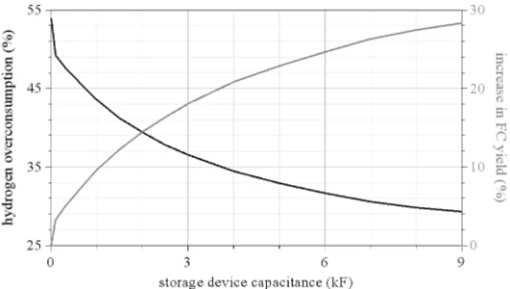
minimum flow rate level on H2 overconsumption. Fig. 8 presents the evolution of H2 consumption over a cycle, as a function of the storage device capacitance. At C = 9000 F, H2 consumption is equal to 5 NL per cycle, and the associated 29% overconsumption is mainly due to the stoichiometric factor.
In summary, supercapacitor directly hybridized with a PEMFC provides a filtering effect that smoothes FC current, which results in increased available FC electrical energy combined with decreased hydrogen consumption. By this way, hybridization contributes to enhance FC yield, defined hereafter as the electrical energy produced per cycle over the hydrogen consumed for its production:
( )
( )
( )
⋅ ⋅ ⋅ = T H T FC FC FC dt t d dt t I t V Y 0 2 0 (5)Fig. 8 gives the variation of the gain in FC yield with the storage device capacitance, with FC alone operation as reference. This gain attains 28 % at C = 9000 F.
Fig. 8. Hydrogen overconsumption (in black) and increase in FC yield (in grey, reference: FC alone operation vs storage device capacitance.
IV. EXPERIMENTAL VALIDATION
A. Experimental Setup
Tests have been carried out using a 100 cm2 PEM single cell, including a seven layered MEA composed of a 50 μm thick membrane, two Pt catalyst layers, and two 285 μm thick GDL. A cooling system based on a thermostatic water bath enables to maintain FC temperature at 55 °C, and air humidity is kept at 57 % by means of a bubbling humidifier. For PEMFC direct hybridization, one or three paralleled 3000 F-2.5 V supercapacitors are used. Either FC alone or hybrid source are loaded by a so-called "zero volt" electronic load operated in current controlled mode.
A dSPACE® real time card (computation sample time: 100 μs), in combination with Controldesk® software and Matlab-Simulink® mathematical environment, is used for the test bench supervision (inlet gas flows settings, active load remote control, safety shutdown), as well as for data acquisition and recording (acquisition sample time: 100 ms).
B. Experimental Results
In each configuration (FC alone, FC directly hybridized with one 3000 F supercapacitor, or with three paralleled 3000 F supercapacitors), six FC-DLC cycles have been recorded, in order to estimate the number of cycles required to reach steady state operation, and to discard unsteady cycles from the data analysis. As obtained in simulation, steady state behavior is attained during the first cycle.
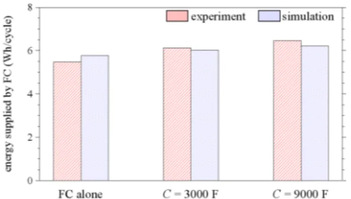
Fig. 9, 10 and 11 compare experimental and simulated results, obtained on fuel cell RMS current, energy supplied by fuel cell over a cycle, and hydrogen consumption, respectively. As it can be seen, experimental trends are as the calculated ones: direct FC hybridization with supercapacitor leads to a decrease in both fuel cell RMS current and hydrogen consumption, and to an increase in fuel cell produced energy. The error made on RMS current and hydrogen consumption is less than 0.5 %, which means that instantaneous current contributions of fuel cell and supercapacitor are accurately calculated. The error made on power produced is also low but slightly higher, at about 5 % in FC alone operation, and less than 4 % in hybridization configuration. This is due to the 1D FC model used, which is not fully accurate in its description of FC voltage in transient.
Fig. 9. Experimental and simulated FC RMS current, obtained for FC alone, for C = 3000 F, and for C = 9000 F.
Fig. 10. Experimental and simulated energy supplied by fuel cell over a cycle, obtained for FC alone, for C = 3000 F, and for C = 9000 F.
V. CONCLUSION
This article highlights the FC efficiency enhancement thanks to the filtering effect provided by a supercapacitor directly hybridized with a fuel cell. By smoothing FC current waveform, the storage device firstly enables to decrease FC electrical losses. Secondly, it significantly reduces hydrogen overconsumption due to gas flow safety levels. As a result, using a large supercapacitor directly paralleled with a single FC can be a solution to achieve substantial gains in FC yield.
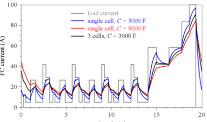
Clearly, such a huge storage capacitance in parallel with a single fuel cell may appear a bit disproportionate. However, one has to keep in mind that this study is a preliminary one. It will be followed by investigations on direct hybridization of a fuel cell stack, with a supercapacitive stack. For this purpose, one can take a great advantage of supercapacitor rated voltage, which is for some recent devices up to 3 times higher than single FC open circuit voltage. For example, one 3 V-3000 F supercapacitor can be paralleled with a 3-cell stack. Ideally, this association is equivalent to a cell-to-cell direct hybridization with 9000 F, while involves 9 times less components. In practice, these really attractive scale factors (3 for the equivalent cell-to-cell capacitance and 1/9 for the actual number of components) are a bit mitigated, because of electrical losses in the supercapacitor and in the hybrid source internal connection. However, they remain significant. Fig. 12 compares simulated FC current waveforms over a FC-DLC cycle, obtained for a single cell hybridized with either 3000 F or 9000 F, and for a 3-cell stack hybridized with 3000 F.
Fig. 11. Experimental and simulated hydrogen consumption over a cycle, obtained for FC alone, for C = 3000 F, and for C = 9000 F. Black lines correspond to the minimum hydrogen consumption, i.e. 3.86 NL/cycle.
Fig. 12. Simulated FC current waveforms over a FC-DLC cycle. Blue curve: single FC hybridized with C = 3000 F, red curve: single FC hybridized with
C = 9000 F, black curve: 3-cell FC stack hybridized with C = 3000 F, grey
curve: load current.
As it can be seen in Fig. 12, the equivalent cell-to-cell hybridization capacitance of the 3-cell stack is far greater than the capacitance used, although it is not the triple. Energy feature analysis, which results in the present case in:
• a IFCRMS/IFCMEAN ratio of 1.22,
• a decrease in FC electrical losses of 12 %, • a hydrogen overconsumption of 31.3 %, • an increase in FC yield of 25 %,
leads (see Fig. 7 and 8) to an equivalent cell-to-cell hybridization capacitance of about 6000 F, thus twice greater than the capacitance used, while involving 6 times less components.
ACKNOWLEDGMENT
This work was supported partly by the French PIA project «Lorraine Université d’Excellence», reference ANR-15-IDEX-04-LUE for the PhD grant allocated to D. Arora.
REFERENCES
[1] H. -C. B. Jensen, E. Schaltz, P. S. Koustrup, S. J. Andreasen, K. S. Knudsen, “Evaluation of fuel-cell range extender impact on hybrid electrical vehicle performance,” IEEE Transactions on Vehicular Technology, vol. 62, n° 1, pp. 50-60, January 2013.
[2] A. Taniguchi, T. Akita, K. Yasuda, Y. Miyazaki, “Analysis of electrocatalyst degradation in PEMFC caused by cell reversal during fuel starvation,” Journal of Power Sources, vol. 130, n° 1-2, pp. 42-49, May 2004.
[3] J. S. Martinez, D. Hissel, M. -C. Péra, M. Amiet, “Practical control structure and energy management of a testbed hybrid electric vehicle,” IEEE Transactions on Vehicular Technology, vol. 60, n° 9, pp. 4139-4152, November 2011
[4] J. Bernard, S. Delprat, F. N. Büchi, T. M. Guerra, “Fuel-cell hybrid powertrain: toward minimization of hydrogen consumption,” IEEE Transactions on Vehicular Technology, vol. 58, n° 7, pp. 3168-3176, September 2009
[5] I. Lachhab, L. Krichen, “An improved energy management strategy for FC/UC hybrid electric vehicles propelled by motor-wheels,” International Journal of Hydrogen Energy, vol. 39, n° 1, pp. 571-581, January 2014
[6] H. Aouzellag, K. Ghedamsi, D. Aouzellag, “Energy management and fault tolerant control strategies for fuel cell/ultra-capacitor hybrid electric vehicles to enhance autonomy, efficiency and life time of the fuel cell system,” International Journal of Hydrogen Energy, vol. 40, n° 22, pp. 7204-7213, June 2015
[7] P. Garcia, J. P. Torreglosa, L. M. Fernandez, F. Jurado, “Viability study of a FC-battery-SC tramway controlled by equivalent consumption minimization strategy,” International Journal of Hydrogen Energy, vol. 37, n° 11, pp. 9368-9382, June 2012
[8] Q. Li, W. Chen, Z. Liu, M. Li, L. Ma, “Development of energy management system based on a power sharing strategy for a fuel cell-battery-supercapacitor hybrid tramway,” Journal of Power Sources, vol. 279, pp. 267-280, April 2015
[9] A. Nishizawa, J. Kallo, O. Garrot, J. Weiss-Ungethüm, “Fuel cell and Li-ion battery direct hybridization system for aircraft applications,” Journal of Power Sources, vol. 222, pp. 294-300, January 2013
[10] B. Morin, D. Van Laethem, C. Turpin, O. Rallières, S. Astier, A. Jaafar, O. Verdu, M. Plantevin, V. Chaudron, “Direct hybridization fuel cell – ultracapacitors,” Fuel Cells, vol. 14, n° 3, pp. 500-507, June 2014 [11] M. Hinaje, S. Raël, J. -P. Caron, B. Davat, “An innovating application of
PEM fuel cell: current source controlled by hydrogen supply,” International Journal of Hydrogen Energy, vol. 37, n° 17, pp. 12481-12488, September 2012
[12] K. Gérardin, S. Raël, C. Bonnet, D. Arora, F. Lapicque, “Direct coupling of PEM fuel cell to supercapacitors for higher durability and better energy management,” Fuel Cells, doi: 10.1002/fuce.201700041, in press
[13] K. Dannenberg, P. Ekdunge, G. Lindbergh, “Mathematical model of the PEMFC,” Journal of Applied Electrochemistry, vol. 30, n° 12, pp. 1377-1387, December 2000
[14] M. Ceraolo, C. Miulli, A. Pozio, “Modelling static and dynamic behaviour of proton exchange membrane fuel cells on the basis of electro-chemical description,” Journal of Power Sources, vol. 113, n° 1, pp. 131-144, January 2003
[15] J. J. Baschuk, X. Li, “A general formulation for a mathematical PEM fuel cell model,” Journal of Power Sources, vol. 142, n° 1-2, pp. 134-153, March 2005
[16] D. Yu, S. Yuvarajan, “Electronic circuit model for proton exchange membrane fuel cells,” Journal of Power Sources, vol. 142, n° 1-2, pp. 238-242, March 2005
[17] S. Lazarou, E. Pyrgioti, A. T. Alexandridis, “A simple electric circuit model for proton exchange membrane fuel cells,” Journal of Power Sources, vol. 190, n° 2, pp. 380-386, May 2009
[18] P. Noiying, M. Hinaje, P. Thounthong, S. Raël, and B. Davat, “Using electrical analogy to describe mass and charge transport in PEM fuel cell,” Renewable Energy, vol. 44, pp. 128-140, August 2012
[19] S. Buller, E. Karden, D. Kok, R. W. De Doncker, “Modeling the dynamic behavior of supercapacitors using impedance spectroscopy,” IEEE Transactions on Industry Applications, vol. 38, n° 6, pp. 1622-1626, December 2002
[20] F. Belhachemi, S. Raël, B. Davat, “A physical based model of power electric double-layer supercapacitors,” IEEE-IAS 2000, pp. 3069-3076, Rome, Italy, October 2000
[21] G. Tsotridis, A. Pilenga, G. De Marco, T. Malkow T, “EU harmonised test protocols for PEMFC-MEA testing in single cell configuration for automotive applications,” JRC Science for Policy Report, available on website http://publications.jrc.ec.europa.eu/, 2015