Publisher’s version / Version de l'éditeur:
Vous avez des questions? Nous pouvons vous aider. Pour communiquer directement avec un auteur, consultez la première page de la revue dans laquelle son article a été publié afin de trouver ses coordonnées. Si vous n’arrivez pas à les repérer, communiquez avec nous à [email protected].
Questions? Contact the NRC Publications Archive team at
[email protected]. If you wish to email the authors directly, please see the first page of the publication for their contact information.
https://publications-cnrc.canada.ca/fra/droits
L’accès à ce site Web et l’utilisation de son contenu sont assujettis aux conditions présentées dans le site LISEZ CES CONDITIONS ATTENTIVEMENT AVANT D’UTILISER CE SITE WEB.
Internal Report (National Research Council of Canada. Institute for Research in
Construction), 1992-01
READ THESE TERMS AND CONDITIONS CAREFULLY BEFORE USING THIS WEBSITE. https://nrc-publications.canada.ca/eng/copyright
NRC Publications Archive Record / Notice des Archives des publications du CNRC :
https://nrc-publications.canada.ca/eng/view/object/?id=e02995d8-1979-44ba-9a6b-9d5d3a920e9f https://publications-cnrc.canada.ca/fra/voir/objet/?id=e02995d8-1979-44ba-9a6b-9d5d3a920e9f
NRC Publications Archive
Archives des publications du CNRC
For the publisher’s version, please access the DOI link below./ Pour consulter la version de l’éditeur, utilisez le lien DOI ci-dessous.
https://doi.org/10.4224/20358480
Access and use of this website and the material on it are subject to the Terms and Conditions set forth at
Experimental Studies on the Fire Resistance of Hollow Steel Columns
Filled with Plain Concrete
.
.
E...
R e f
;-
:xg
#: Is,
.
Ser
+'+< I
TH1
National Research Consell national
-
b .%-
-
- t R 4 2 7Council Canada
de recherches Canada
I
?
't
-
-
T ' . ,B L D G
061
institute for lnstitut deResearch in recherche en
:i
9;
4 Construction construction1 %
Expcern'memRaA
St~oTAes
om
the
~ebtiistnmce
O P
MQ~!(OW
R~MA
:
.
-4
!?,a
,?
+k-
" s+ T.T. Lie and M. Chaboti h l *+.
2.::-
...
J
' " ; ./.-
$1, b e .
Internal Report No. 61 1 Date of issue: January 1992
/
I'L I B R A R Y
I ! 4I
l r l A R c ! y !
1
I 1. i'BIBLIOTHLQUE
I
I R C
I Cf'IRt-
tCI6T.
!
This is an internal report of the Institute for Research in Construction. Although not intended for general distribution, it may be cited as a reference in other publications
EXPERIMENTAL STUDIES ON THE FIRE RESISTANCE OF HOLLOW
STEEL COLUMNS FILLED WITH PLAIN CONCRETE
T. T. Lie and M. Chabot
ABSTRACT
Experimental studies were carried out to determine the fire resistance of circular and
square hollow structural steel columns filled
with
plain concrete. The results of
44
full-
scale fire resistance tests
are
described. The study variables included the column
dimensions, steel section wall thickness, concrete
strength,
type of concrete aggregate,
effective length, load intensity and eccentricity. These studies
were
conducted as part
of
a
research program aimed at developing methods capable of predicting the
fire
resistance
of
concrete-filled hollow steel columns.
1.
INTRODUCTION
Steel Hollow Structural Sections (HSS) are very efficient structural sections in
resisting compression loads. By filling these sections with concrete, a substantial increase
in load-bearing capacity can be achieved. Also, frre resistance can be obtained without the
necessity of external fire protection for the steel section. The elimination of such external
surface protection increases usable space in the building, and allows the steel outer surface
to be left exposed. Furthermore, the tubular sections eliminate the need for formwork
during erection.
These perceived benefits have resulted in research into the structural and
fireperformance of concrete-filled hollow steel columns in several organizations around the
world [I-81. For a number of years, the National Fire Laboratory of the Institute for
Research in Construction, National Research Council of Canada, has also been engaged in
studies to develop methods for predicting the
fireresistance of these composite columns.
These studies were supported by the Canadian Steel Construction Council and the
American Iron and Steel Institute. A multi-phase program, which involves mathematical
modelling and experiments, was set up. The study variables included the column cross-
section shape and dimensions, thickness of steel section wall, effective length, concrete
strength, type of concrete aggregate, percentage of steel reinforcement in the concrete
as
well
as
load intensity and eccentricity.
The report deals with the first phase of this program which focussed on hollow
steel columns filled with plain concrete. The results of 44 tests on full-size circular and
square columns, including the column cross-section temperature, axial deformation and fue
resistance, are described in detail. The results of these tests can be used in two ways.
First, the results
cin
be used to assess, by interpolation, the fire resistance of columns in
particular applications. Secondly and most importantly, they can be used to validate
mathematical models which predict the behaviour of concrete-filled hollow steel columns
exposed to fire [9].
This report includes
all
information previously published in two intermediate test
reports by the Institute for Research in Construction in 1988 [10,11].
2.
DESCRIPTION OF TEST SPECIMENS
2.1.
Dimensions
All 44
columns were 3810 mm (12 ft 6 in.) long from end plate to end plate.
Thirty-eight columns had a circular cross-section and 6 columns had a square cross-
section. The outer diameter of the circular columns ranged from 141.3 mm to 406.4 mm,
while the steel wall thickness varied from 4.78 mm to 12.70 mm. The outside width of the
square columns ranged from 152.4 mm to 304.8 mm and the thickness of the steel wall
was 6.35 mm. The dimensions of each column are listed in Table 1. In this table, the
columns whose number s t .
with "C" are circular, and those with a number starting with
"SQ"
are square.
2.2.
Materials
Steel hollow structural sections (HSS) meeting the requirements of CSA Standard
G40.20-M [12], Class H, were used. The sections were made with grade 300W and
350W steels (CSA Standard G40.21-M [13]) with minimum yield strengths of 300 MPa
and 350 MPa respectively. The sections were supplied by Stelco Inc.
The end plates were constructed using mild steel.
2.2.2. Concrete
Two types of concrete were used, i.e., siliceous and carbonate aggregate concretes.
Of the
44
columns, 24 were filled with siliceous aggregate concrete and the others with
carbonate aggregate concrete. Twelve pours were made in the National Fire Laboratory of
the Institute for Research in Construction to fdl the 44 columns. Batch quantities and
specifics of the concrete mixes used in each pour are given in Tables 2,3 and 4. The pours
were numbered sequentially for the entire concrete-filled hollow steel column project
according to the date of pouring.
In all pours, but Pour No. 10, a general purpose Type 10 Portland cement for
construction of concrete structures was used. In Pour 10, a high early strength Type 30
Portland cement was used.
The concrete mixes in Pour Nos. 1 , 2 , 3 , 4 and 17 were made with siliceous
aggreate concrete. The aggregates were of nearly homogeneous siliceous composition.
Rose quartz (coarse aggregate) from Northbrook, Ontario and siliceous sand (fine
aggregate) supplied by Indusmin Ltd. from St Canut, Quebec were used in Pour Nos. 1-4.
In Pour No. 18, the coarse and fine siliceous aggregates were supplied by Daubois Inc.
from Saint-Leonard; Quebec.
The aggregates in Pour Nos. 5,6,7,8, 10, 11 and 18, were dominantly of
carbonate composition. Carbonate stone from Ottawa (supplied by Dufferin Concrete) was
used as aggregate in Pour Nos. 5 , 6 , 7 , 8 and 11, while dolomite stone from Kingston,
Ontario, was used in Pour No. 10. The fine aggregate used was silica based sand from
Ottawa (supplied by Dufferin Concrete).
In Pour Nos. 10 and 11 (Column Nos. 42 and 46), additives were included in the
mixes to increase the concrete compressive strength. These were silica fume and fly ash.
In some cases, superplasticizer Mithty 150 and retarding admixtures Master Builders
100 XR and Mulco TCDA 727 were added to the mix to improve workability.
Compression tests on 150 mm cylinders were conducted for each pour at 28 days
and on the test dates. The 28-day cylinder compressive strength ranged from 23 to
43 MPa. In the case of the concrete mixes with fly ash and silica fume, however, higher
strengths were achieved. The 28-day cylinder strength of the mixes with fly ash was
49 MPa and that of the mix with silica fume was 90 MPa. The concrete strengths at
28 days and on the test dates are given in Table 1 for each column.
2.3,
Fabrication
The columns were fabricated by cutting the supplied hollow steel sections to
appropriate lengths. Steel end plates were then welded to the section extremities. The
hollow steel sections and end plates were fust joined by a groove weld. Secondly, a fillet
weld was added around the outside diameter of the hollow steel section. AWS 5.18 Type
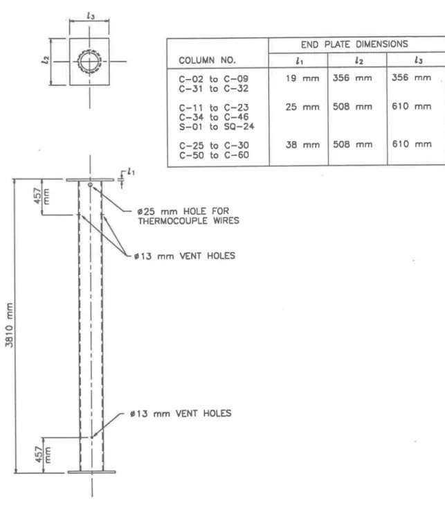
E705-6 welding rods were used for both welds. Plate thickness and dimensions varied
with the diameter of the hollow steel sections as shown in Figure 1. The hollow steel
sections were cut to length so that the column length was 3810 mm including the end plate
thickness. Accurate centering and perpendicularity of the end plates were given special
attention.
Before assembly, a hole was cut in each pIate to
provide
an opening through which
the concrete was poured. The hole was approximately
25.4
mm smaller
in
diameter than
the inner diameter of the hollow steel section,
thuscreating a
lip
of
13
mm
between
the
inner surface of the section and the edges of the opening
in the
end plate, as shown in
Figure 2.
Five small holes were drilled in the wall of the steel hollow sections. Two pairs,
13 mm in diameter, located 457 mm from each end of the columns, were provided
as
vent
holes for the water vapour pressure produced during the experiment. The
fifth
hole,
located near the top end plate, was used for entry of the thermocouple wires (see Figure 1).
The columns were then put in an upright position and filled with concrete. The
concrete was mixed in a truck mixer, except for Pour No. 10 where a 0.17 m3 drum type
mixer was used. A concrete placement bucket and a funnel were used to deposit the
concrete in the steel column.
An internal vibrator was carefully applied to consolidate the
concrete. The top surface of the column was finished with a small trowel. To avoid
possible moisture leaks, the section was sealed at both ends with plastic sheet and tape.
The columns were left upright for 28 days, then stored horizontally at room temperature
with no particular curing measures being taken, until the test date. In general, seven
months or more elapsed between the time a column
was
poured and the time it was tested.
In a few cases, however, the curing period was limited to 4 to 5 months.
Before each test, the moisture condition in the concrete core of the column was
measured by inserting a resistance moisture sensor in a hole drilled in the concrete through
one of the vent holes. In general, a moisture content corresponding to approximately 85 to
95% RH was measured.
2.4. Instrumentation
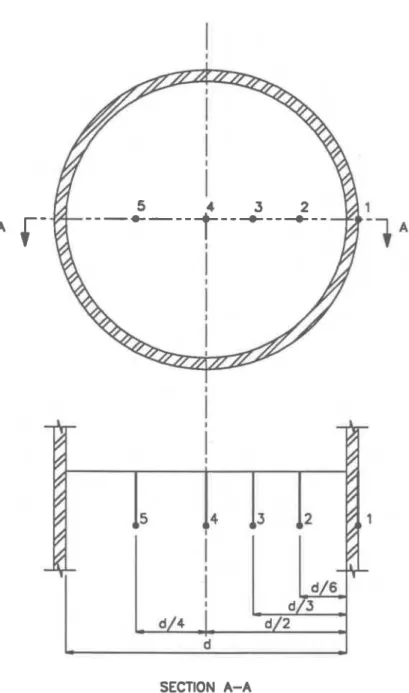
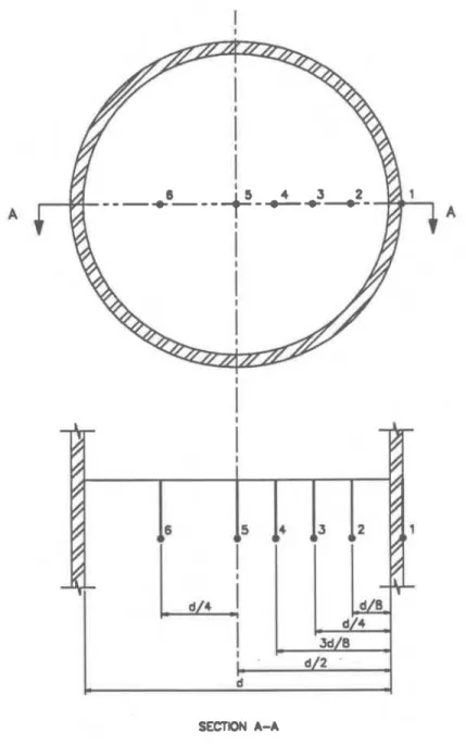
Type K chromel-alumel thermocouples, with a thickness of 0.91 mm, were used
for measuring concrete temperatures at several locations across the mid-height section of
the columns. The thermocouples were tied to a steel rod that was secured to a bar running
along the longitudinal axis of the column. The bar was fixed at both ends of the column
(see Figure 3). In addition, a thermocouple was attached to the steel wall of each column at
mid-height. The locations of the thermocouples
are
shown in Figures 4 to 6.
3.
TEST APPARATUS
The tests were carried out by exposing the columns to heat in a furnace specially
built for testing loaded columns and walls. The test furnace was designed to produce the
conditions to which a member might be exposed during a fire; i.e., temperatures, structural
loads and heat transfer. It consisted of a steel framework supported by four steel columns,
with the furnace chamber inside the framework (Figure 7). The characteristics and
instrumentation of the furnace are described in detail in Reference [14]. Only a brief
description of the furnace and the main components is given here.
3.1 Loading device
A
hydraulic jack with a capacity of 9778 kN produced the load along the axis of the
test column. The jack was located at the bottom of the furnace chamber.
3.2. Furnace chamber
The furnace chamber had a floor area of 2642
x2642 mm and was 3048 mm high.
The interior faces of the chamber were lined with ceramic fibre materials that efficiently
transfer heat to the specimen. There were 32 propane gas burners in the furnace chamber,
arranged in eight columns containing four burners each. The total capacity of the burners
was
4700
kW.
Each burner can be adjusted individually, which gave a high degree of
temperature uniformity in the furnace chamber. The pressure in the furnace chamber was
also adjustable and was set somewhat lower than atmospheric pressure.
3.3 Instrumentation
The furnace temperatures were measured with the aid of eight chromel-alumel
thermocouples. The junction of each thermocouple was located 305 mm (1 ft) from the test
specimen, at various heights. Two thermocouples were placed opposite each other at
intervals of 610 mm (2 ft) along the height of the furnace chamber. The location of their
junctions and their numbering are shown in Figure 8. The temperatures measured by the
thermocouples were averaged automatically and the average temperature used as the
criterion for controlling the furnace temperature.
The loads were controlled and measured using pressure transducers. The accuracy
of controlling and measuring loads is about 5% at lower load levels and relatively better at
higher loads.
The axial deformation of the test specimen was determined by measuring the
displacement of the jack that supports the column. The displacement was measured using
transducers with an accuracy of 0.002 mm.
4.
TEST CONDITIONS AND PROCEDURES
4.1
End conditions
Most tests were carried out with both ends of the columns fixed, i.e., restrained
against rotation and horizontal translation. For this purpose, eight 19 mm bolts spaced
regularly around the column were used at each end to bolt the end plates to the loading head
at the top and the hydraulic jack at the bottom. Three columns (Column Nos. C-06, C-15
and C- 16), however, were tested under hinged end conditions, i.e., with restraint against
horizontal translation only. In these cases, the column end plates were bolted to the
receiving plate with a roller bearing at each end.
4.2.
Loading
All columns were tested under a concentric load, except Column No. C-16 where
the load was eccentric by 34 mm. The applied load ranged from 9 to 47% of the factored
compressive resistance of the columns (C,,) or 46 to 165% of the factored compressive
resistance of the concrete core (C',), determined according to CSA Standard CSAJCAN-
S 16.1-M89 [15]. The factored compressive resistances of each column, as well as the
applied loads, are given in Table 1. The effective length factors, K, used in the calculation
the factored compressive resistances were those recommended in CSAICAN-S 16.1-M89
for the given end conditions, i.e., 0.65 for fixed ends and 1 for pinned ends. The effective
lengths, KL, were thus 2.48 m for fixed ends and 3.81 m for pinned ends.
The load was applied approximately 45 min before the start of the test, until a
condition was reached at which no further increase of the axial deformation could be
measured. This condition was selected
as
the initial condition for the column axial
deformation. The load was maintained constant throughout the test.
4.3. Fire exposure
The ambient temperature at the start of each test was approximately 20°C. During
the test, the column was exposed to heating controlled in such a way that the average
temperature in the furnace followed as closely as possible the ASTM-El19 [16] or
CAN/ULC-S101 [17] standard temperature-time curve. This curve can be approximated
by the following equation:
where:
Tf
=
Furnace temperature (OC)
t
=
Time (hours)
4.4.
Failure criterion
The columns were considered to have failed, and the tests were terminated, when
the hydraulic jack, which has a maximum speed of 76 mmlmin (3 inJmin), could no longer
maintain the load.
4.5
Recording of results
The furnace, concrete and steel temperatures,
as
well as the axial deformations of
the columns were recorded at 2,5 or 10 min intervals.
The test program was conducted over a ten year period, i.e., from 1981 to 1990.
During that period, modifications to the furnace equipment, such as the temperature
controller, burners and lining materials, as well as improvements in the data acquisition
system were made which may have some influence on the results. Special attention was
given, however, to ensure that the test conditions, such as
temperature uniformity and heat
transfer from the furnace to the columns, remained essentially unaltered.
5.
RESULTS
AND
DISCUSSION
The results of the 44 column tests
are
summarized in Table 1. Specific information,
test conditions, fire resistance and failure modes are given for each column. The failure
mode, which varied from buckling to compression, was determined by visual observation.
A column was considered to have failed by buckling when bending was apparent.
The concrete and steel temperatures,
as
well
as
the axial deformations of the
columns as a function of time, are presented in Tables A1 to A44 and plotted in Figures A1
to A44, in Appendix
A.
Positive axial deformation values indicate expansion of the
column. Finally, Figures
B1
to B44, in Appendix B show photographs of the column
specimens taken after the fire tests.
As
mentioned earlier, these tests were carried out essentially for the purpose of
validating methods
capable
of calculating
the
fireresistance of hollow steel columns filled
w i ~
plain concrete for
any value
of
thc
significant variables which determine fire
resistance. The development of such
me
[hod!; is at
an
advanced stage at the National Fire
Laboratory
and
willbe prescnted
ina
future
paper. The test results given in this report can
also
beused
for ascssing
thcfirc
resistanceof hollow steel columns filled with plain
concrete
-
in particular, applications which fit within the range of values of the significant
variables considered in the test series. The following discussion on the behaviour of the
columns in fire and the influence of the study variables should provide additional
information for the fire resistance design of hollow steel columns filled with plain concrete.
5.1
Behaviour of concrete filled hollow steel columns in fire
The behaviour of a concrete-filled hollow steel column in frre can
be
determined by
examining the axial deformation curve of the column in the fm test. The axial deformation
curve of Column No. 34 in Figure A23 represents a typical example.
At ambient temperature, the applied column load is carried by both the hollow steel
section and the concrete core. When the column is exposed to fire, both the steel section
and concrete core start to expand. This is indicated by the steep increase in axial
deformation in Figure A23. During that stage, the steel section carries all of the applied
load because it expands more rapidly than the concrete core. As the temperature increases,
however, the steel loses its ability to support the load and the column suddenly contracts
until, usually after 20-30 min, the concrete takes over. This
is
often accompanied by local
bulging of the steel section. The load is then gradually transferred to the concrete core
which loses strength more slowly than the steel due
to
the lower thermal conductivity and
higher heat capacity of the concrete. The column then progressively continues to contract,
as the concrete temperature increases, and ultimately fails, either by buckling or
compression, depending on the slenderness of the column. At failure, the load is usually
almost entirely carried by the concrete core.
Thus, it is the load-carrying capacity of the concrete core, during exposure to fire,
that determines the fire resistance of concrete filled steel columns. Because the concrete
section alone cannot support the full design load, a high fire resistance can only be achieved
by reducing the applied load.
5.2
Influence of study variables
Load intensity
The load intensity is defined
as
the ratio of the applied load to the column resistance
(load bearing capacity) at room temperature. Two values of the load intensity are given in
Table 1 for each column test, one as a fraction of the factored compressive resistance of the
composite column (CIC,) and the other
as
a fraction of the factored compressive resistance
of the concrete core only (CIC',), determined in accordance with CANJCSA-S16.1-M89.
For fire resistance design, the ratio of applied load to the factored compressive resistance of
the concrete core (CIC',) was considered as more representative of the actual intensity of
loading because, as mentioned earlier, of the dominant contribution of the concrete filling in
carrying the applied load. The strength of the hollow steel section, which is included in the
calculation of C,, decreases very quickly
in
fm and can practically be neglected. The ratio
CIC',, rather than CIC,, should thus be used for comparing different test results.
The influence of the load intensity on the
fireresistance of the column is illustrated
in Figure 9 for three different column diameters.
As
expected, the load intensity has a
significant influence on the fire resistance of the column. For example, the fire resistance
of Column Nos. C-20, C-21 and C-22 decreased from 133 to 70 min as the applied load
increased from 74 to 141% of the factored compressive resistance of the concrete core.
The influence of the load intensity had a relatively larger influence for columns having a
larger diameter.
Outside diameter or width of column
In general, for the same load intensity, the fire resistance increased with the outer
diameter or width of the columns. The reason
is
that the heat capacity of the concrete core
increases with its mass. As a result, the temperature at comparable depths inside the
concrete core rises more slowly in large columns than in small columns.
The fire resistances of circular columns were relatively higher than those of square
columns, for equivalent cross-section area.
Steel wall thickness
The influence of the steel wall thickness was investigated in Test Nos. C-05, C-09,
C-1
1
and C- 17, as well as C-35 and C-37. All these columns had a relatively small outer
diameter, namely 219.1 mm or less. As expected, it was found that the wall thickness had
little influence on the fire resistance of the columns. For Column Nos. C-05 and C-09, for
example, which were tested under the same load, the fire resistance increased from 76 to
81 min by increasing the wall thickness from 4.78 to 6.35 mm. In the case of Column
Nos. C-35 and C-37, the opposite effect was observed, i.e., that the fire resistance
decreased with increasing wall thickness.
It seems reasonable, for practical applications, to neglect the influence of the wall
thickness. Hollow steel sections with thin wall thiclcneses thus appear more cost-effective.
Tests on conventional reinforced concrete columns, 305 mm by 305 mm, carried
out at NRC [18], showed that, for columns having comparable strengths, carbonate
aggregate concrete provides substantially higher
fire
resistances than siliceous aggreagate
concrete, particularly for long fire resistance durations or implicitly for low load intensities.
Under an applied load of 58% of the design load, for example, the fue resistance of a
carbonate aggregate concrete column was more than twice as high as that of a comparable
siliceous aggregate concrete column. The reason is that carbonate aggregate has a
substantially higher heat capacity than siliceous aggregate concrete as a result of an
endothermic reaction that occurs in carbonate aggregate around 700°C.
The results obtained in the series of tests on concrete filled hollow steel columns,
however, were less conclusive regarding the influence of the type of aggregate, because the
siliceous and carbonate aggregate mixes had somewhat different compressive strengths,
and the carbonate aggregate mixes were not pure but contained silica-based sand. There are
indications, however, that better performance can be expected by using carbonate aggregate
concrete, such as lower temperature deep
in
the concrete core and extremely high fire
resistances (234,274 and 294 min) under loads of approximately 55% of C',.
Concrete strength
Here again, it is difficult to draw conclusions on the influence of the concrete
strength on the fire resistance of the columns for the same reasons mentioned in the
previous section. There are indications, however, that, for a given load, the fire resistance
increases with concrete strength, when the 28-day strength ranges between 25 and 45 MPa.
The fire resistance of Columns No. C-59 and C-60, for example, increased from 125 to
152 min with an increase of the concrete strength from 33 to 43 MPa.
Effective length
The influence of the effective length was examined for two different column
diameters, i.e., 168.3 mm and 219.1 mm (Column Nos. C-05, C-06, C-15 and C-17). As
expected, for the same applied load, the
fireresistance decreased with increase of effective
length. For example, for the columns with a diameter of 168.3 mm, the fire resistance
decreased from 76 min to 60 min when the effective length was increased from 2477 mm to
3810 mm. The reduction
in
fire resistance with increase of effective length varied with the
slenderness of the column.
Eccentricitv
Only one test was conducted to examine the influence of the load eccentricity
(Column No. C-16). The column had a diameter of 219.1 mm and the eccentricity of the
applied load was 34 mm.
As
expected, the eccentricity had a significant effect on the fire
resistance of the column. For the same applied load, the fire resistance decreased from
73 min to 33 min as a result of the eccentricity of loading. Because concrete has practically
no tensile strength, it is not recommended that hollow steel columns filled with plain
5.3 Repeatability of test results
In this test series, a column can be placed in two classes based on its failure mode.
The columns with a small diameter, i.e., 219.1 mm or less, failed by buckling whereas the
larger columns, 323.9 mm or more in diameter, failed in compression. The failure mode of
the columns with a diameter of 273.1
mm
varied between buckling and compression. In
general, the results obtained for the small columns are consistent from test to test. The
performance of the larger columns in the tests, however, was sometimes erratic, especially
when the load was high. In some cases, the failure by compression occurred very
suddenly, without warning. This behaviour is probably due to the development of local
excessive stresses and cracks which propagates through the concrete core due to the
absence of steel reinforcement and lack of containment of the concrete. Increased
REFERENCES
1. Flemington, R.A., Fire Protection of Hollow Structural Sections, Technical Bulletin
21, Stelco Inc., Hamilton, Ontario, 1980.
2. Granjean, G., Grimault, J.P. and Petit, L., Determination de la Duree au Feu des
Profils Creux Remplis de Beton, Rapport Final, Commission des Communaut6s
Europeennes, Recherche Technique Acier, Luxembourg, 198 1.
3. Kordina, E.H.K. and Klingsch, W., Brandverhalten von Stahlstiitzen
irn
Verbund mit
Beton und von massiven Stahlstiitzen ohne Beton, Teil
1:
Bericht, Institut fur
Baustoffe, Massivbau und Brandschultz Lehrstuhl fiir Massivbau, Technische
Universitiit Braunschweig, West Germany, 1983.
4. Design Manual for SHS Concrete Filled Columns, British Steel Corporation, Corby
Technical Centre, U.K., 1984.
5.
Kruppa, J., Methode de fibvision par le Calcul du Comportement au Feu des poteaux
Mixtes (Acier
+
Beton), Construction Mitallique, No. 3, 1988.
6 .
Twilt,
L.,
Design Charts for the Fire Resistance of Concrete Filled HSS Columns
under Centric Loading, TNO Institute for Building Materials and Structures,
Netherlands, 1988.
7. Klingsch, W. and Wittbecker, F.W., Fire Resistance of Hollow Section Composite
Columns of Small Cross Sections, Bergische Universitiit, Wuppertal, West Germany,
1988.
8. Fire Technical Design Manual for Composite Columns with Concrete Filled Hollow
Steel Sections, Finnish Constructional Steelwork Association, Helsinki, 1989.
9. Lie, T.T. and M. Chabot, A Method to Predict the Fire Resistance of Circular Concrete
Filled Hollow Steel Columns, Journal of Fire Protection Engineering, Vol. 2, NO. 4,
1990, pp 1 1 1
-
126. (Reprinted by the National Research Council of Canada
as
NRCC
32372).
10.
T.T. Lie and
S.E.
Caron, Fire Resistance of Circular Hollow Steel Columns Filled
with Siliceous Aggregate Concrete: Test Results, Internal Report No. 570, Institute
for Research in Construction, National Research Council of Canada, Ottawa, Canada,
August 1988.
1 1. T.T. Lie and S.E. Caron, Fire Resistance of Circular Hollow Steel Columns Filled
with Carbonate Aggregate Concrete: Test Results, Internal Report No. 573, Institute
for Research
in
Construction, National Research Council of Canada, Ottawa, Canada,
November 1988.
12. General Requirements for Rolled or Welded Structural Quality Steel
-
G40.20-M,
Canadian Standards Association, Toronto.
13. Structural Quality Steels
-
G40.21-M, Canadian Standards Association, Toronto.
14. Lie, T.T., New Facility to Determine Fire Resistance of Columns, Canadian Journal of
Civil Engineering, Vol. 7, No. 3, 1980, pp 551-558. (Reprinted by the National
Research Council of Canada as NRCC 18423)
1
5.
Limit States Design of Steel Structures
-
CAN/CSA-S16.1 -M89,
Canadian Standards
Association, Toronto.
16.
Standard Methoa's of Fire Tests of Building Construction and Materials
-
El
19-83,
American Society for Testing and Materials, Philadelphia, 1985.
1 7 .
Standard Methodi of Fire Endurance Tests of Building Construction
and
Materials
-
CANlULC-SlOl
-M89, Underwriters' Laboratories of Canada, Scarborough, Canada,
1982.
18.
Lie, T.T. and Woollerton, J.L., Fire Resistance of Reinforced Concrete Columns
-
Test Results, Internal Report No. 569, Institute for Research in Construction, National
Research Council of Canada, Ottawa, Canada, 1988.
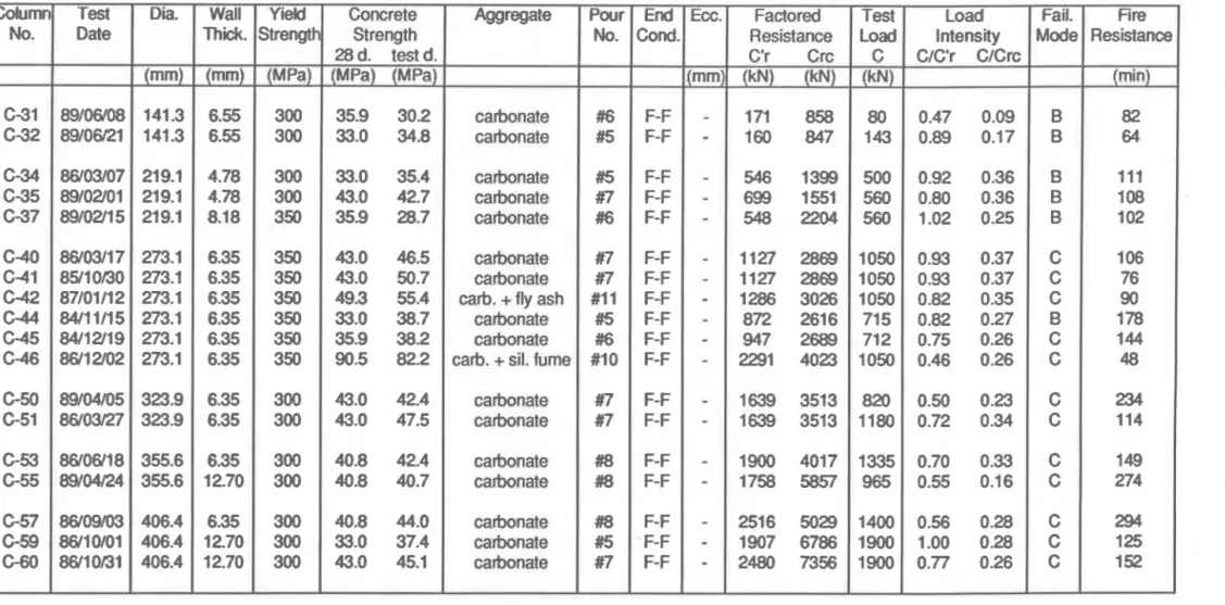
Table 1. Summary of test parameters and results Column No. C-02 C-04 C-05 C-06 C-08 C-09 C-11 C-13 C-15 C-16 C-17 C-20 C-21 C-22 C-23 C-25 C-26 C-28 C-29 C30 Test Date 89/03/01
83/09M
89/03/10 90/03/29 85/02/13 89/03/22 84/12/03 84/04/10 90/01/l8 90/03/19 84/07/10 82/05/07 82'06'18 83/07/21 89/08/01 83/01/18 85/08/29 85/09/16 85/10/15 86/02/26 Dia. (mm) 141.3 141.3 168.3 168.3 168.3 168.3 219.1 219.1 219.1 219.1 219.1 273.1 273.1 273.1 273.1 323.9 323.9 355.6 355.6 406.4 Wall Thick. (mm) 6.55 6.55 4.78 4.78 4.78 6.35 4.78 4.78 8.18 8.18 8.18 5.56 5.56 5.56 12.70 6.35 6.35 6.35 12.70 12.70 Meld Strength (MPa)---
350
350 350 350 350 350 350 350 350 350 350 350 350 350 350 350 350 350350
350
Fail. Mode B B B B B B B B B B B B B B Bc
C C C C fire Resistance (min) 5557
76 60 56 81 80 1 02 73 33 82 112 1 33 70 1 43 1 45 93 111 1 70 71 Concrete Strength 28 day test (MPa) (MPa) 28.6 33.1 28.6 31 .O 28.6 32.7 28.6 32.7 28.6 35.5 28.6 35.4 24.3 31.0 24.3 32.3 24.3 31.9 24.3 31.9 24.3 31.7 26.3 28.6 26.3 29.0 26.3 27.2 26.3 27.4 23.5 27.6 23.5 24.3 23.5 23.8 23.5 25.4 23.5 27.6 Aggregate Pour No.End
Cond. siliceous siliceous siliceous siliceous siliceous siliceous siliceous siliceous siliceous siliceous siliceous siliceous siliceous siliceous siliceous siliceous siliceous siliceous s i l i i s siliceous Test Load C (kN) Load Intensity C/C'r C/CE-
-
-
-
-
-110 131 150 150 218 150 492 384 525 525 525 574 525 1000 525 699 1050 1050 1050 1900 Ecc. (mm) 0 . n 0.12 0.92 0.14 0.60 0.16 0.84 0.19 0.87 0.23 0.63 0.13 1.21 0.35 0.94 0.27 1.65 0.28-
0.47 1.39 0.26 0.81 0.26 0.74 0.23 1.41 0.45 0.83 0.13 0.77 0.23 1.16 0.34 0.96 0.29 1.03 0.18 1.40 0.27 Factored Resistance C'r Crc (kN) (kN) 143 928 143 928 250 965 179 798 250 965 238 1177 408 1399 408 1399 319 1849-
1128 379 2039 708 2243 708 2243 708 2243 629 3991 903 3090 903 3090 1099 3570 1018 5801 1360 7051 #4 #4 #4 #4 #4 #4 #3 #3 #3 #3 #3 #I #1 #I #1 #2 #2 #2 #2 F-F F-F F-F P-P F-F F-F F-F F-F P-P P-P F-F F-F F-F F-F F-F F-F F-F F-F F-F F-F-
-
-
-
-
-
-
-
- 34 --
-
-
-
-
-
--
-
Table 1 (cont'd). Summary of test parameters and results Column No. C31 C-32 C-34 C35 C37 C40 C41 C-42 C-44 C-45 C46 C-50 C-51 C-53 C-55 C-57 C-59 G60 Test Date
---
89/06/08 89/06/21 86/03/07 89/02/01 89/02/15 86/03/17 85/10130 87/01/12 84/11/15 84/12/19 86/12/02 89/04/05 86/03/27 86/06/18 89/04/24 86/09/03 86/10/01 86/10/31 Dia. jmm) 141.3 141.3 219.1 219.1 219.1 273.1 273.1 273.1 273.1 273.1 273.1 323.9 323.9 355.6 355.6 406.4 406.4 406.4 Wall Thick. 6.55 6.55 4.78 4.78 8.18 6.35 6.35 6.35 6.35 6.35 6.35 6.35 6.35 6.35 12.70 6.35 12.70 12.70 Yield Strength 300 300 300 300 350 350 350 350 350 350 350 300 300 300 300 300 300 300 Concrete Strength 28 d. test d. 35.9 30.2 33.0 34.8 33.0 35.4 43.0 42.7 35.9 28.7 43.0 46.5 43.0 50.7 49.3 55.4 33.0 38.7 35.9 38.2 90.5 82.2 43.0 42.4 43.0 47.5 40.8 42.4 40.8 40.7 40.8 44.0 33.0 37.4 43.0 45.1 Aggregate(mm)(MPa)(UPa)O--r
cabnate carbonate carbonate carbonate carbonate carbonate carbonate arb.+
fly ashcarbonate cahnate
carb.
+
sit.fume
carbonate carbonate carbonate carbonate carbonate carbonate carbonate Pour No. #6 #5 #5 #7 #6 #7 #7 #11 #5 #6 #10 #7 #7 #8 #8 #8 #5 #7 End Cond. F-F F-F F-F F-F F-F F-F F-F F-F F-F F-F F-F F-F F-F F-F F-F F-F F-F F-F Ecc. mm) -
-
- --
-
-
-
--
-
-
-
-
-
-
-
-
Factored Resistance C'r Crc (kN) (kN) 171 858 160 847 546 1399 699 1551 548 2204 1127 2869 1127 2869 1286 3026 872 2616 947 2689 2291 4023 1639 3513 1639 3513 1900 4017 1758 5857 2516 5029 1907 6786 2480 7356 Test Load C (kN) 80 143 500 560 560 1050 1050 1050 715 712 1050 820 1180 1335 965 1400 1900 1900 Load Intensity C/C'r C/Crc 0.47 0.09 0.89 0.17 0.92 0.36 0.80 0.36 1.02 0.25 0.93 0.37 0.93 0.37 0.82 0.35 0.82 0.27 0.75 0.26 0.46 0.26 0.50 0.23 0.72 0.34 0.70 0.33 0.55 0.16 0.56 0.28 1.00 0.28 0.77 0.26 Fail. Mode B B B B B C C C B C C C C C C C Cc
Fire Resistance (min) 82 64 111 108 1 02 106 76 90 1 78 1 44 48 234 114 1 49 274 294 1 25 1 52Table 1
(cont'd).
Summaryof
test parameters and results Notes:End
conditions: F-F = Fuced-
Foced P-P = Pinned-
Pinned Factored Resistance:C'r = Factwed m p m s i v e resistance of concrete core as per CAN341 6.1 -M89 Crc = Factored compressive resistance of
composite
column as per CAN341 6.1-M89Fire Resistance (min) 66 86
80
62 97 131Failure Mode:
B = BucklingC
= Compression Fail. Mode B B Bc
C C Load Intensity C/C'r C/Crc-
-
-
-1.05 0.26 0.86 0.20 1.01 0.29 0.87 0.34 0.80 0.30 0.60 0.27 Test Load C (kN) 376 286 549 1096 931 1130 Aggregate-
-
-
-
-
-
-
-
-siliceous carbonate siliious siliious carbonate siliceous Column No. SQ-01 SQ-02 SQ-07 SQ-17 SQ-20 SQ-24 Wall Thick. (mm) 6.35 6.35 6.35 6.35 6.35 6.35 Pour No. #17 #18 #17 #17 #18 #17 Test Date--
90/0&22 9011 1/16 90/06/01 90/07/26 90/11/27 90/12/19 YieM Strength (MPa) 350 350 350 350 350 350 W~dth (mrn) 152.4 152.4 177.8 254.0 254.0 304.8End
Cond. F-F F-F F-F F-F F-F F-F Concrete Strength 28 d. test d. (MPa) (MPa) 43.5 58.3 40.2 46.5 43.5 57.0 43.5 58.3 40.2 46.5 43.5 58.8 Ecc. (mm)-
-
-
-
-
-
Factored Resistance C'r Crc (kN) (kN) 358 1462 334 1439 541 1866 1257 3220 1164 3127 1868 4247Table 2. Batch quantities and properties of siliceous aggregate concrete mixes
Cement (kg/ cu.m)
Coarse aggregate (kglar. m)
19 - 15.9 mm (314
-
5/8 in.)15.9
-
9.5 mrn (5/8-
318 in.) 9.5 - 4.8 mm (318-
3/16 in.)Total
Fine aggregate (kgku. m)
# I 0 #16 #24 #40 #70 Total Additives (kg/cu.
rn)
Water (kg/at.rn)
WaterICernent ratio Superplasticizer Retart3ng admixlure 28 day cowressive strength (MPa) Pour No. 1 81/06/09 Siliceous 366 435 435 250 1120 111 222 85 1 37 1 05 660 190 0.52-
26.3
Pour No. 2 8111 0108 Siliceous 366 435 435 237 1107 112 222 85 138 104 661-
190 0.52-
-
23.5 Pour No. 3 81 11 0122 Siliceous 377 437 437 239 11 13 112 224 85 138 106 665-
1 93 0.51-
24.3 Pour No. 4 8111 1/05 Siliceous380
438 438 240 1116 113 225 86 143 106 673 186 0.49-
28.6 Pour No. 17 8911 1/06 Siliceous380
438 438 240 1116 113 225 86 143 1 06 673 1 67 0.44 Mighty 1 50 M u b TCDA 727 43.5ii
Figure 1. Column specimen details and dimensions
COLUMN NO. C-02 to C-09 C-31 to C-32 C-1 1 to C-23 C-34 to C-46 S-01 to SQ-24 C-25 to C-30 C-50 to C-60END PLATE DIMENSIONS
1s 3 5 6 rnrn 6 1 0 m m 6 1 0 r n m 11 19 rnrn 2 5 m m 3 8 m m 12 3 5 6 rnrn 5 0 8 m m 5 0 8 m r n
Figure
4.
Locations of thermocouples in cross-section
of Column
Nos.
C-02 to
C-09
and
C-31
to C-32
SECTION A-A
Figure
5.
Locations of thermocouples in cross-section of Column
Nos.
C-11 to
C-30
and
C-34 to C-60
SECTION A-A
Figure
6.
Locations of thermocouples in cross-section of Column
Nos.
SQ-01 to
SQ-24
TOP
VIEW
DOUR
j/
COLUMN FURNACE CHAMBER
FRONT
VIEW
CEILING INSULATION 1 7 I - 5 3-
2 8 0 d. -4. 0 cu m a2
- 6 4 - N5
2
rO 1 FLOOR INSULATIONLoad intensity C/C'r
Figure
9.
Influence of load intensity CIC'r on fire resistance of hollow steel columns filled
with plain concrete
Table Al. Temperatures and axial deformation of Column No. C-02 Std. furn. temp.
("cy
20 Avg. furn.I
temp. (OC)1
Column cross-section temperature (OC) measured at Thermocouple No. 1 2 3 4 5 32 18 18 18 18 68 20 18 18 19 95 27 20 19 24 116 38 25 23 32 148 50 32 30 42 285 118 51 74 55 381 1 27 93 1 26 83 443 151 111 138 112 500 151 1 22 117 138 536 150 1 32 144 1 57 566 150 1 52 153 155 603 1 47 1 47 153 168 140 630 203 1 40 163 657 240 136 135 185 679 276 142 134 207 700 308 161 1 44 231 71 9 335 1 89 171 257 732 360 219 203 283 741 385 247 232 31 1 754 41 1 275 259 338 769 439 303 286 363 468 783 497 330 312 389 796 356 337 414 809 526 381 360 440 822 554 407 381 467 832 585 432 398 494 842 607 455 419 519 852 627 477 439 543
Measurements not reliable
Axial
OP-
-.Q
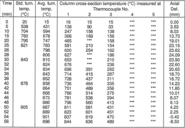
Table A2. Temperatures and axial deformation of Column No. 604 Std. fum. temp.
I
"
C
)
20 538 704 760 795 821 Avg. fum. temp. (OC) 15 431 594 678 747 783 798 806 81 0 824 834 843 852 858 864 868 873 886 887 889 901 898Column cross-section temperature (OC) measured at Thermocouple No. 1 2 3 4 5 16 15 15 .C. *C. 136 90 33 .n m 247 156 1 38 m m 366 1 69 156 m ttt 485 *.r. 158 * m 581 21 0 1 54 m m 600 254 1 62 C U *... 627 m 1 86 m m 653 *H 21 0 m m 676 *C. 236 m m 696 391 262 m m 71 4 41 5 287 C U m 728 437 31 1 .H m 736 464 335 m m 751 489 356 *H C..+ 766 514 375 *- m 781 538 394 m ...t 796 560 41 3 *H *H 81 1 581 431 * *H 823 601 451 *H m 837 61 9 470 m *.r. 844 636 489 m m Axial Def
.
0
0.00 3.53 8.03 13.73 19.01 23.1 5 23.62 24.09 I I I ITime (min)
0
10
20
30
40
50
60
Time (min)
Table A3. Temperatures and axial deformation of Column No. W 5 Time (min) 0 2 4 6 8 10 12 14 16 18 20 22 24 26 28 30 32 34 36 38 40 42 44 46 48 50 52 54 56 58 60 62 64 66 68 70 72 74 76
'"
Std. fum. temp. ("C) Avg. fum. temp. PC)Column cross-section temperature ("C) measured at Thermocouple No. 1 2 3 4 5 20 Axial Def. (mm) 18 13 13 13 13 49 0.00 0.33 1.01 2.34 6.57 1 1.09 14.01 16.43 18.65 20.30 21.63 22.64 22.77 20.61 16.96 14.38 12.67 11.21 10.05 9.09 8.24 7.47 6.79 6.1 7 5.56 4.95 4.34 3.76 3.14 2.39 1.39 0.1 5 -1.40 -3.23 -5.38 -8.02 -1 1.31 -1 5.78 -23.88 46 16 13 13 13 76 23 15 14 14 1 24 33 19 16 18 246 93 86 63 59 328 1 22 120 122 121 389 117 117 117 117 440 121 120 120 1 20 442 126 1 26 125 1 49 425 129 129 1 24 132 125 1 27 126 126 458 126 501 131 126 1 28 185 286 704 795 434 673 71 2 708 728 751 766 782 797 843 809 81 9 828 837 562 131 130 127 126 598 129 130 123 625 154 125 1 24 123 624 171 126 123 129 846 624 116 119 116 123 61 7 141 119 118 1 33 649 1 78 123 1 24 156 675 207 132 136 179 704 243 144 1 49 201 730 289 164 164 222 747 336 1 99 1 85 243 771 376 230 21 1 263 788 41 0 259 236 283 803 441 285 280 303 81 6 470 310 302 323 829 496 334 323 343 843 51 7 357 342 363 854 537 379 360 382 862 556 400 379 401 871 573 41 7 398 41 7 878 587 436 41 7 435 883 600 455 434 451 891 61 0 473 452 469 897 61 7 489 471 482 901 623 503 486 497 908 629 51 7 501 51 1 91 3 634 531 519 521 reliable 878 905 854 862 867 875 881 885 893 896 901 g n 946 907 907 91 5 91 9 922 929 930 932 938 941 944 949 951 Measurements not
0
0
10
20
30
40
50
60
70
80
90
Time (min)
- -
= Stondard F'urnace Temp.-
Average F i rnace Tlsmp.0
10
20
30
40
50
60
70
80
90
Time (min)
Table A4. Temperatures and axial deformation of Column No. C-06
Std. fum.
I
Avg. fum20 50 444 569 626 647 704 666 695 71 5 733 71 1 795 I 763 786 799 81 3 828 843 837 845 856 860 866 878 875 880 883 891 897 905 899 905 91 5 91 7 91 9 Measurements not re
Column cross-section temperature (OC) measured at Thermocouple No. 2 3 4 5 able Axial Def.
0
0.00 1.03 4.21 7.54 9.95 12.83 14.78 16.49 17.90 18.43 20.14 21.58 21.66 19.65 16.64 13.98 12.03 10.37 9.08- -
= Standard f'urnace Tamp.-
Average FL rnace Tamp.Time (min)
0
10
20
30
40
50
60
70
80
90
Time
(min)Table A5. Temperatures and axial deformation of Column No. C-08
Column cross-section temperature (OC) measured at Thermocouple No. 1 2 3 4 5 43 25 26 25
25
1 95 26 26 25 26 245 28 27 26 31 327 123 112 115 49 382 110 1 26 1 27 70 428 1 02 115 121 90 485 111 1 20 121 112 **. 548 122 122 123 ..r. 581 1 24.*.
1 24 1 25 627 1 20 120 121 ..t 659 118 118 118 683 115 116 116 1 25 696 119 118 120 145 708 1 24 123 1 24 1 65 71 9 1 27 125 125 181 735 129 1 24 1 24 1 97 135 1 24 123 21 3 762 750 148 129 1 25 230 777 1 69 141 133 250 796 1 95 160 145 269 807 221 184 1 64290
81 8 246 208 1 89 31 2 827 270 232 214 333 836 293 255 237 354 851 31 6 277 258 374 867 339 298 278 395 867 360 319 298 41 4 876 381 339 31 7 434 896 401 358 336 453 Std. furn. temp. (OC) 20 704 795 able Avg. furn temp.!"C)
I ' 52 483 557 621 646 695 728 765 784 790 801 Axial Def.
(mm! 0.00 1.41 3.55 6.09 8.78 1 1.86 15.08 18.10 20.13 20.48 19.80 15.26 1 1.93 10.01 8.55 7.37 6.31 5.45 843 878 905 81 5 825 833 840 848 856 862 871 084 878 884 888 893 904 91 3 905 91 1 91 7 Measurements not reTime (min)
Time (min)
Table A6. Temperatures and axial deformation of Column No. C-09
-
Time Std. fum. Avg. fum.
1
temp. !"C) 20 704 795 843 878 temp. YC)1
I IColumn cross-section temperature ("C) measured at Thermocouple No.
905
927
946
963
I Measurements not reliable
Axial Def. lmml r 0.00 0.25 1.78 5.62 8.1 0 10.49
Time (min)
Time (rnin)