Publisher’s version / Version de l'éditeur:
ACI Structural Journal, 93, November 6, pp. 721-728, 1996-11-01
READ THESE TERMS AND CONDITIONS CAREFULLY BEFORE USING THIS WEBSITE. https://nrc-publications.canada.ca/eng/copyright
Vous avez des questions? Nous pouvons vous aider. Pour communiquer directement avec un auteur, consultez la première page de la revue dans laquelle son article a été publié afin de trouver ses coordonnées. Si vous n’arrivez pas à les repérer, communiquez avec nous à PublicationsArchive-ArchivesPublications@nrc-cnrc.gc.ca.
Questions? Contact the NRC Publications Archive team at
PublicationsArchive-ArchivesPublications@nrc-cnrc.gc.ca. If you wish to email the authors directly, please see the first page of the publication for their contact information.
NRC Publications Archive
Archives des publications du CNRC
This publication could be one of several versions: author’s original, accepted manuscript or the publisher’s version. / La version de cette publication peut être l’une des suivantes : la version prépublication de l’auteur, la version acceptée du manuscrit ou la version de l’éditeur.
Access and use of this website and the material on it are subject to the Terms and Conditions set forth at
Evaluation of moment redistribution in a two-span continuous
prestressed concrete beam
Kodur, V. K. R.; Campbell, T. I.
https://publications-cnrc.canada.ca/fra/droits
L’accès à ce site Web et l’utilisation de son contenu sont assujettis aux conditions présentées dans le site
LISEZ CES CONDITIONS ATTENTIVEMENT AVANT D’UTILISER CE SITE WEB.
NRC Publications Record / Notice d'Archives des publications de CNRC:
https://nrc-publications.canada.ca/eng/view/object/?id=58fb979b-0e56-4833-87ae-b64499f83a42 https://publications-cnrc.canada.ca/fra/voir/objet/?id=58fb979b-0e56-4833-87ae-b64499f83a42http://www.nrc-cnrc.gc.ca/irc
Eva lua t ion of m om e nt re dist ribut ion in a t w o-spa n c ont inuous
pre st re sse d c onc re t e be a m
N R C C - 4 0 6 0 4
K o d u r , V . R . ; C a m p b e l l , T . I .
N o v e m b e r 1 9 9 6
A version of this document is published in / Une version de ce document se trouve dans:
ACI Structural Journal, 93, (6), November, pp. 721-728, November 01, 1996
The material in this document is covered by the provisions of the Copyright Act, by Canadian laws, policies, regulations and international agreements. Such provisions serve to identify the information source and, in specific instances, to prohibit reproduction of materials without written permission. For more information visit http://laws.justice.gc.ca/en/showtdm/cs/C-42
Les renseignements dans ce document sont protégés par la Loi sur le droit d'auteur, par les lois, les politiques et les règlements du Canada et des accords internationaux. Ces dispositions permettent d'identifier la source de l'information et, dans certains cas, d'interdire la copie de documents sans permission écrite. Pour obtenir de plus amples renseignements : http://lois.justice.gc.ca/fr/showtdm/cs/C-42
ゥ、セ
I
on an led of of to tal Ig. of イ。セ IT. ity セゥセACI STRUCTURAL JOURNAL
TECHNICAL PAPER
Title no. 93·S69
Evaluation of Moment Redistribution in a
Two-Span Continuous Prestressed Concrete Beam
by Venkatesh Kumar R. Kodur and T.
I. Campbell
6
An approach is proposed for determining the percentage of redistribution of moment occurring at failure of a continuous prestressed concrete beam. The approach, which is based on two parameters-the percentage of redis-tribution xand the moment ratio MR-was developed using results from nonlinear finite element analyses of a large number of continuous pre-stressed concrete beams. In the propo:;ed approach. the available redistri-bution of moment is based un the overall structural behavior rather than on the cross-sectional behavior.
Keywords: continuous beam; nonlinear analysis; prestressed concrete; redistribution of moment; secondary moment.
The bending moments in a continuous beam can be pre-dicted using a linear-elastic analysis. provided the load level is such that the elastic limit is not exceeded in any of the con-stituent materials. When the elastic limit is exceeded, at any particular load level, the bending moments in the beam will likely differ from those predicted by a linear-elastic analysis. The difference for a particular load level between the actual moment at a section and that determined by a linear-elastic analysis is referred to as redistribution of moment.
The failure load of a continuous prestressed concrete beam depends on the extent of redistribution of moment that oc-curs prior to failure. The extent of redistribution of moment can be full, partial, or nil, depending on a number of fac-tors.1.2To determine the actual amount of redistribution of moment occurring, a nonlinear analysis has to be carried out.
Design codes for concrete structures usually recommend the use of a linear-elastic analysis and either ignore the non-linear effect or recognize it by applying a somewhat arbitrary adjustment to the design elastic moments. Even to date, there is debate on the extent of redistribution permitted by differ-ent codes of practice.1·3
The extent of redistribution of moment in a continuous prestressed concrete beam depends on a number of factors. Parametric studies conducted by KodurZ have demonstrated that the stiffness of the span and the presence of secondary moments influence the extent of redistribution of moment, ACI Structural Journal! November-December 1996
and it has been recommended that overall structural ductility be considered in determining the amount of redistribution. The majority of current codes of practice4-6base the
allow-able amount of redistribution of moment on cross-sectional ductility at a critical section, and do not take secondary moments into account in determining the permitted amount of redistribution of moment. Although some codes of practice7recommend the use of a detailed nonlinear analysis for determining the extent of redistribution of moment, the applicability of such an approach is limited in many design situations due to the complexity and the effort involved. Some studiesS•9 have called for development of simple
ap-proaches for determining redistribution of moment, and an attempt is made to develop such an approach in the cur-rent investigation.
A theoretical expression to determine the extent of redis-tribution of moment is derived and a reasonably simple method for predicting the failure load of a continuous pre-stressed concrete beam is proposed in this paper. The appli-cability of the method of design is demonstrated through a numerical example.
INVESTIGATION
The majority of previous studies on continuous prestressed concrete beams considered only some of the parameters that have been shown to affect redistribution of moment. Only a few investigators, such as Santamaria,1O Moucessian and Campbell,s and Scholz,IIconcentrated on developing a simple approach to determine the redistribution of moment for ap-plication in a design situation. The studies of Santamaria and Moucessian and Campbell are important since they were
ACI Structural Journal, V. 93, No.6, November-December 1996.
Received Aug. 28, 1995, and reviewed under Institute publication policies. Copy-right© 1996, American Concrete Institute. All rights reserved, including the making of copies unless pennission is obtained from the copyright proprietors. Peninent dis-cussionwill be published in the September-October 1997 ACI Structural Journal if received by May I. 1997.
Spans
722
(2)
(3)
x PARI = IOO-x MR whereandMBand Meare the ultimate moment capacities of the span and support critical sections, respectively,a is the ratio of the distance of the span critical section from the end sup-port to the span length, when the span and center supsup-port section ultimate strengths are developed simultaneously,
s,
is a fac-tor used in defining the bending moment at the central*The Appendixes are available in xerographic or similar form from ACI headquar. ters. where they will be kept permanently on file, al a charge equal to the COSI of reproduction plus handling at time ofrequest.
ACI Structural Journal/November-December 1996 where Weol, W", and Wpl are the failure loads based on non-linear, elastic, and plastic analyses, respectively. By intro-ducing the relevant expressions for We.o" W", and Wpl in tenns of the. moment capacities and secondary moments at the span and support critical sections (see Appendix A*),the percentage of redistribution of momentxcan be related to the parameter PARI as follows
( x)
3 I I(d
)
M sec lOO-x=2
E1(EJ-B) L+
O.1m ,Kセ]yェョ・Kyウ・」
c cy c
(I) THEORETICAL EXPRESSION FOR
REDISTRIBUTION OF MOMENT .. GNセZ By equating the total available rotation at the central sup: port region with the inelastic rotation required to -achieve a percentage of redistributionxin a symmetric two-span pre-stressed concrete beam (Fig. I), the following expression can be derived (see Appendix A*)
where EIis a measure of the flexural stiffness of the span,
EIeis the flexural stiffness at failure of the support critical section,Eleyis the flexural stiffness of the support section at first yield of the reinforcement,dis the distance from the ex-treme compression fiber to the center of the tension force at the support section, L is the span length, M"c is the second-ary moment at the support section, Meis the moment ca-pacity of the support section, andm,is a factor to account for the type of loading (see Appendix A*).The flexural stiff-ness, at any load level, is defined as the ratio of the moment to the curvature. The termsYil1eandYsec in Eq.(1)represent the extent of redistribution resulting from inelastic action and secondary moments, respectively. Eq.(I)was derived in a manner similar to that used by Mattock.12
The parameter PARI may be defined as
Two-span Beam \tith Unequal
W
w
,..---:1'---_,__1__,
I-
L'I-
L"I
(b) Symetrie Two-span Beem
セ
セ
V
w
w
I
I
A!--"'--8-,"'-C
--L,..,S'--'
A'
11----
L1---"I"
L2
---"I
(e)ACI member T.I. Campbell is a prqfessor and Head of the Department ofCivil Eng;-neering at Queens University. He holds BSc, PhD, and DSc degrees from Queen's UniverSity, Belfast, Northern Ireland. He is a member alld past chairman ofACI Committee 358, Concrete Guideways. andamemberofjoint ACI-ASCE Committee
343,Concrete Bridge Design.
Venk4tesh Kumar R. Kodurisa research associate at the National Fire LAboratory at the Inuitute of ResearchinConstruction at the National Research Council ofCan· ada, Ottawa. He received his MSc and PhD degrees from Queen
s
University. Kingston, Canada. His research interests include nonlinear analysis of concrete structures and evaluation offire resistance offiber reinforced and high-strength con-crete structural elements.(e) Mement Dlagrem ter Symetrle Two-span Beam Fig. I-Twa-span beam with concentrated loading
based on the concept of structural ductility, unlike Scholz's study, which was based on cross-sectional ductility. San-tamaria did not reach any conclusion since no definite trend was observed in his proposed PAR-cld relationships, where PAR (plastic adaptation ratio) was defined in terms of load factors, andc1das the ratio of neutral axis depth- to-effective depth of a section at ultimate.
Moucessian and Campbell proposed an approach based on PARI·MR relationships, where PARI was defined in terms ofthree failure loads;asthe ratio of the extent of redistribution that occurred to the maximum redistribution possible in a beam, and MR was arbitrarily defined as the ratio of the dif-ference of the ultimate moment and secondary moment at the support section to that at the critical section in the span. However, the applicability of this approach is limited since .the data on which it is based were obtained from the nonlinear analysis of beams in which only a limited number of param-eters were varied. Factors such as cross-sectional shape, con-crete strength, and span-depth ratio were not considered. The present study attempts to overcome some of the limitations of the PARI-MR approach, and to develop a rational ap-proach for determining the extent of redistribution of mo-ment in a continuous prestressed concrete beam.
(Il PCSlT (c) N". peST, PLUO. pes. PPI
£J
--I ;5:1-- 800 4,.- 711 • • 100 I 1 2 0 0 1Mol.1 All D,,,,lMlant . . III """ Ito!f. SCole
• •
2500• •
1
1 ::: {セッNッ
r1
l 1 : : : aーNセRSW•
•
- ''"''==00'" -- 250 1200 (e) I'CSI--11501--.0'
(b) Cross Section '048 (d) PCS. --I '051--(0) UNTw Parabolic Tendon Profile
セZ
1
112.501
112S01
11250I
11250t
(UNT) 12192 12192 12192 ; 12192. •
(0) Structure Gnd l..oadlng
1600
セG
NolIN All Dlm_lon. aN !II mm Hott. !iN"
A
..'"
a⦅NZZZZQZUPセZZQ
セセN
lZZZZAZZ]ZZiMNjセY
aセ]ZLSXNW-w
Unear Tendon Profile 1600 I I_ 1600®
and loadIng (b) Cross Sectronw
1600 _I(b
(0) Structuresupport (see Appendix A'), andT
r
= 1.0 for a concentrated load and 2.0 for a uniformly distributed load in each span.Substituting forxJ(lOO - x)from Eq. (I)in Eq. (3) gives Fig. 2-Layout of Group A beams(J in. =25.4 mm)
pan, :ical 10at ex-:eat md- ea-: for tiff-leot ient tion din (I) ec
!
I
jSU P-' Ive a :pre-can(2)
on- tra-I in i at the Ito(3)
(4) the .tio Jp-,on lC-ral uar-tofIt can be seen from Eq. (4) thatMR accounts not only for the moment capacities and secondary moments at the critical sections, but also for the location of the span critical section and the type of loading.
From Eq. (1) or Eq. (5), it can be inferred that:
a. The extent of redistribution of moment increases with stiffness of the span, plastic hinge length (reflected by the term 0.1 ml)'and secondary momentM"c
b. The greater the value ofEl
c
corresponding to a higherc1dratio at the support section, the lower the amount of re-distribution will be.
c. An increase in the span-depth ratio lid results in de-creased redistribution of moment.
d. The extent of redistribution of moment is influenced by the type ofloading as reflected by the factorsaandSl in the
expression forMR[Eq. (4)].
e. Concrete strength and partial prestressing index, whose effects are accounted for indirectly in the computation ofMR
through the values ofMBand Me,also influence the extent of redistribution.2
In Eq.(I),as a conservative estimate, the stiffness of Span
EIcan be assumed to be equal to the stiffness of the critical span section at yield of the reinforcement, and d can be as-sumed to be equal to the total depth of the member. Since the derivation of Eq. (I) is based on a number of simplifying
as-*The Appendixes are available in xerographic or similar form from ACI headquar-ters, where they will be kept permanently on file. at a charge equal to the cost of reproduction plus handling at time ofイ・アオ・NセエN
Fig. 3-Layout of Group B beams(J in. =25.4 mm)
sumptions, its applicability may be limited in practice. Never-theless, this relationship is useful in identifying the various parameters that influence the extent of redistribution of mo-ment in a two-span prestressed concrete beam,
REDISTRIBUTION OF MOMENT USING NONLINEAR ANALYSIS
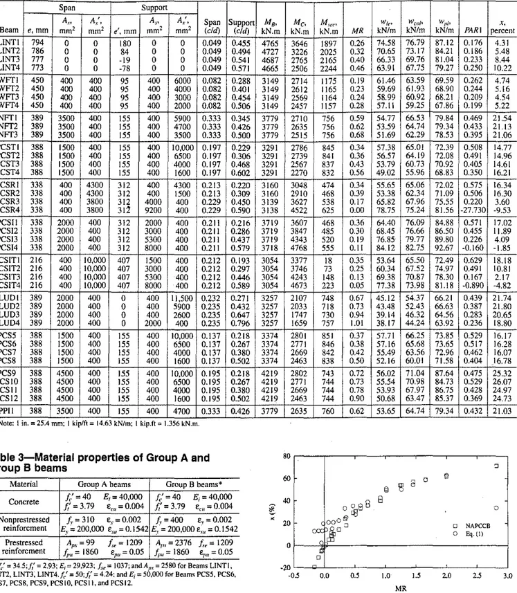
To establish the validity of the expressions derived in the previous section, and to examine the influences of the differ-ent parameters, a detailed parametric study was carried out. Sixty-six beams, which were divided into two groups (Group A and Group B), were analyzed using a computer pro-gram,2,13,14 and the failure load was evaluated in each case. The parameters varied, and includedEIandc/dat the support and span critical sections, type of loading, cross-sectional shape, span-depth ratio, concrete strength, secondary mo-ment, and partial prestressing index.
Twenty-six of the beams studied by Moucessian15 were
selected as Group A beams. All the beams were symmetric over two spans of 3.2 m (10.5 ft) each, had a rectangular cross section 150-mm-(5.9-in.)-wide and 250-mm-(9.8-in.)-deep, and were subjected to a concentrated load at the center of each span (Fig, 2).
The 40 Group B beams, which were selected from the two-span beams used in the parametric studies of Kodur', Were loaded symmetrically with uniformly distributed load and had wideRranging characteristics, such as cross-sectional shape (rectangular, T, I, and inverted T), secondary moment, concrete strength, andc1dvalues (Fig. 3). The location of the critical section in the span for a beam loaded with uniformly 96 ACI Structural JournalJNovember-December 1996
723
(6)
EVALUATION OF THEORETICAL EXPRESSION FOR PERCENTAGE OF REDISTRIBUTION
To evaluate the validity of Eq. (I), the value ofx (desig-natedXEq) for each beam was computed from this equation and compared with the actual value of percentage of redistri-bution at failure obtained from the computer analysis. The
beam properties required in the computation ofXEq were
readily available from the results of the nonlinear analysis.
The onset of yielding was assumed to occur at a section when either the nonprestressed reinforcement reached a
strain level of 0.002 or the prestressed reinforcement reached a strain level of 0.01.
Fig. 4 shows a comparison of theXEq values and the per-centage of redistribution as obtained from the computer anal-ysis for each of the Group A beams.Itcan be seen thatXEq
compares well with xfrom the computer analysis at higher ACI Structural Journal/November-December 1996 The termW,." in Eq. (6) represents the total load on a span at failure as predicted by the computer analysis.Itshould be noted in Tables I and 2 that the value ofMR, and conse-quentlyx,is less than zero for some beams. These beams had a high c/d value at the support section and a low c/d value at
the critical span section. As a result, the more critical section
is the span section, as opposed to the central support section,
and consequently, redistribution of moment is from the span
to the support section in these beams.
ThePARIvalues close to unity in Table I indicate that
al-most complete redistribution of moment occurred in the
ma-jority of the Group A beams, while partial redistribution occurred in the Group B beams, as indicated by the lower
PARI values in Table 2.
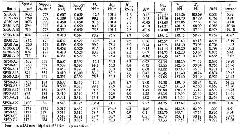
Table 1-Details and results of analyses for Group A beams ...
SpanA,., Support Span Support M,. Me. M,Ii',", WI,,' W,,,/. WI'" x.
Beam mm' A,I·,mm2 (cI<f) (cI<f) kN.m kN.m kN.m MR kN kN kN PARI percent
SP50-AI 1632 1778 0.607 0.650 112.2 101.5 7.8 0.13 182.22 191.86 203.69 0.531 5.39 SP50-A5 1260 1778 0.509 0.650 99.1 101.4 8.5 0.03 183.10 184.70 187.29 0.768 0.94 SP50-A9 1073 1778 0.458 0.650 91.6 101.4 8.8 -0.03 183.68 177.06 177.83 0.741 -4.08 SP50-A13 894 1778 0.410 0.650 83.8 101.4 9.2 ·0.10 184.27 168.15 168.09 0.988 -10.50 SP50-A18 715 1778 0.351 0.650 75.3 101.4 9.5 ·0:16 184.90 157.78 157.44 0.978 -19.10 SP50-A14 894 1378 0.410 0.561 83.8 86.8 8.7 0.00 159.12 158.15 158.92 0.858 ·0.67 SP50-A2 1632 1171 0.607 0.520 112.2 78.4 7.2 0.36 142.57 171.60 189.13 0.604 18.19 SP50-A6 1260 1171 0.509 0.520 99.2 78.4 6.9 0.24 142.25 164.30 173.03 0.706 14.43 SP50-AIO 1073 1171 0.458 0.520 91.6 78.4 8.1 0.15 144.15 159.20 163.43 0.799 10.33 SP50-A15 894 1171 0.410 0.520 83.8 78.4 8.5 0.Q7 144.73 152.20 153.69 0.876 5.41 SP50-A19 715 1171 0.351 0.520 75.3 78.4 8.8 -0.02 145.35 142.70 143.05 0.868 -2.07 SP50-A3 1632 557 0.607 0.390 112.1 50.3 6.3 0.92 94.35 150.20 171.57 0.697 39.99 SP50-A7 1260 557 0.509 0.390 99.1 50.3 6.9 0.72 95.33 142.40 155.34 0.767 35.96 SP50·A11 1073 557 0.458 0.390 91.6 50.3 7.2 0.60 95.88 137.60 145.88 0.821 33.23 SP50·A16 894 557 0.410 0.390 83.8 50.3 7.6 0.47 96.45 131.40 136.14 0.874 29.43 SP50-A20 715 557 0.351 0.390 75.3 50.3 7.9 0.34 97.05 123.40 125.49 0.921 23.92 SP50·A4 1632 184 0.607 0.310 112.1 29.9 5.7 2.00 59.30 139.10 158.84 0.787 61.55 SP50-A8 1260 184 0.509 0.310 99.1 29.9 6.3 1.65 60.27 131.30 142.60 0.852 58.76 SP50-A12 1073 184 0.458 0.310 91.6 29.9 6.6 1.45 60.80 126.20 133.14 0.897 56.75 SP50-A17 894 184 MIO 0.310 83.8 29.9 6.9 1.25 61.35 119.90 123.40 0.939 54.01 SP50-A21 715 184 0.351 0.310 75.3 29.9 7.3 1.02 61.95 111.00 112.76 0.963 49.60 SP50-A22 1400 36 0.548 0.285 104.4 21.1 5.8 2.82 44.75 132.62 143.68 0.882 71.46 SP50·C1 1171 1778 0.517 0.652 78.7 101.7 0.5 ·0.05 170.32 162.38 162.00 1.000 ·4.91 SP50-C2 1171 1171 0.517 0.517 78.7 78.7 0.9 0.11 132.70 145.74 147.64 0.897 9.04 SPSO·C3 1171 557 0.517 0.391 78.7 50.7 1.3 0.51 86.73 124.11 130.12 0.863 30.67 SP50·C4 1171 184 0.517 0.307 78.7 30.3 1.7 1.27 53.33 112,59 117.37 0.927 53.98
distributed load was assumed to be at approximately 0.4 L from the end support.
Prestressing in all beams was by means of bonded
post-tensioning, and varying amounts of nonprestressed
rein-forcement were provided. Details on the amounts of nonprestressed reinforcement are given in TablesI and 2 for Group A and GroupBbeams, respectively,.where the desig-nations (as used by Moucessian" and Kodur2)for identify-ing the beams are adopted. Additional information is given by Moucessian and Campbe1l8and Kodur' for Group A and Group B beams, respectively. The material properties were kept constant for Group A beams, while some of the proper-ties were varied for Group B beams. The properties of the
concrete,nonprestressed, and prestressed reinforcement, as
well as the amounts of prestressed reinforcement, are given
in Table 3. The maximum compressive strain in the concrete
at failure was assumed to be 0.004 in all cases.
Results from the computer analysis, namely the failure loads, secondary moment,(chi)ratios, and the moment capac-ities of the critical sections, are given in Tables I and 2 for Group A and Group B beams, respectively. The three loads given are the failure loads based on plastic analysis (Wplor
wpl),a computer analysis(Wealorwco/),and an elastic analysis
(WI,orWI,)'The momentsMBandMecorrespond to the mo-ment capacities of the span and the support critical sections, respectively, while M"c' which is the secondary moment at the central support section, is based on an elastic analysis.
The parametersPARI, MR,andxwere evaluated for each beam. The values ofPARI andMRwere computed using the relationships in Eq. (2) and (4), respectively, while the value ofx was computed according to the following relationship [see Eq. (A.14) in Appendix A*l
724
"'The Appendixes are available in xerographic or similar fonn from ACI headquar. ters. where they will be kept pennanently on file, ata charge equal 10 the Cosi of reproduction plUS handling at time of request.
:ent 19 14 08 50 ,10 57 19 43 33 II )7 19 ,6 23 13 J2 55 76 75 JI iO 16 II 4 ;7 '8 (6) pan I be lse-had eat :ion .on, pan
Table 2-Details and results of analyses for Group B beams
Span Support
A.", A/, A.I" A/, Span Support MB, Me, M,I'c,"' w{c' wl'o/, wI''' x,
Beam e,mm mm' mm' e', mm mm' mm' (eft[) (eft[) kN.m kN.m kN.m MR kN/m kN/m kN/m PARI percent
LINT I 794 0 0 180 0 0 0,049 0.455 4765 3646 1897 0.26 74.58 76.79 87.12 0.176 4.31 LINT2 786 0 0 84 0 0 0.049 0.494 4727 3226 2025 0.32 70,65 73.17 84.21 0,186 5.48 LINTJ 777 0 0 -19 0 0 0.049 0.541 4687 2765 2165 0.40 66.33 69.76 81.04 0.233 8.44 LINT4 773 0 0 -78 0 0 0.049 0.571 4665 2506 2244 0.46 63,91 67.75 79.27 0.250 10.22 WFT1 450 400 400 95 400 6000 0.082 0.288 3149 2714 1175 0.19 61.46 63.59 6959 0.262 4,74 WFT2 450 400 400 95 400 4000 0.082 0.401 3149 2612 1165 0.23 59,69 61.93 68.90 0.244 5,16 WFT3 450 400 400 95 400 3000 0.082 0.454 3149 2569 1164 0.24 58.99 60.92 68.21 0.209 454 WFT4 450 400 400 95 400 2000 0.082 0.506 3149 2457 1157 0.28 57,11 59,25 67,86 0.199 5,22 NFT1 389 3500 400 155 400 5900 0.333 0.345 3779 2710 756 0,59 54.77 66,53 79,84 0.469 2154 NFT2 389 3500 400 155 400 4700 0,333 0.426 3779 2635 756 0,62 53.59 64.74 79,34 0.433 21.13 NFT3 389 3500 400 155 400 3500 0.333 0,500 3779 2515 756 0.68 51.69 62.29 78,53 0,395 21.06 PCSTI 388 1500 400 155 400 10,000 0.197 0.229 3291 2786 845 0.34 57,38 65.01 72.39 0,508 14,77 PCST2 388 1500 400 155 400 6500 0,197 0.306 3291 2739 841 0.36 56,57 64,19 72.08 0.491 14.96 PCST3 388 1500 400 155 400 4000 0.197 0.468 3291 2567 837 0.43 53,79 60,73 70.92 0.405 14.61 PCST4 388 1500 400 155 400 1600 0.197 0.602 3291 2270 832 0.56 49,02 55,96 68,83 0.350 16.21 PCSR1 338 400 4300 312 400 4300 0.213 0.220 3160 3048 474 0.34 55.65 65,06 72.02 0.575 16.34 PCSR2 338 400 4300 312 400 1500 0.213 0.309 3160 2910 468 0,39 53.38 62.34 71.09 0.506 16,30 PCSR3 338 400 3800 312 4000 400 0.229 0.450 3139 3627 538 0,17 65.82 67.96 75.55 0.220 3.60 PCSR4 338 400 3800 312 9200 400 0.229 0.590 3138 4522 625 0,00 78.75 75.24 81.56 -27,730 -953 PeSll 338 2000 400 312 2000 400 0.211 0.216 3719 3607 468 0,36 64.40 76.09 84.88 0.571 17.02 PeSl2 338 2000 400 312 3000 400 0.211 0.286 3719 3847 485 0.30 68.45 76.66 8650 0.455 11 ,89 PCSI3 338 2000 400 312 5300 400 0.211 0.437 3719 4343 520 0,19 76.85 79.77 89.80 0.226 4,09 PeSI4 338 2000 400 312 8000 400 0.211 0579 3718 4768 555 0.11 84.12 82.75 92.67 -0.160 -1.85 PCSlTI 216 400 10,000 407 1500 400 0.212 0.193 3054 3377 18 0.35 53,64 65.50 72.49 0.629 18.18 PCSlT2 216 400 10,000 407 3000 400 0.212 0.297 3054 3746 73 0.25 60.34 67.52 74.97 0.491 10.81 PCSITJ 216 400 10,000 407 5300 400 0.212 0.446 3054 4243 148 0.13 69.38 70.87 78.30 0.167 2.17 PCSIT4 216 400 10,000 407 8000 400 0.212 0589 3054 4673 223 0.05 77.38 73,98 81.18 -0.890 -4,82 PLUDI 389 2000 400 0 400 11 ,500 0.232 0.271 3257 2107 748 0.67 45.12 54.37 66.21 0.439 21.74 PLUD2 389 2000 400 0 400 5900 0,235 0.432 3257 2033 718 0.73 43.48 52.43 66.63 0,387 21.80 PLUDJ 389 2000 400 0 400 2600 0.235 0.647 3257 1747 730 0.94 39.14 46,32 6456 0.283 20.65 PLUD4 389 2000 400 0 2000 400 0,235 0.796 3257 1659 757 1.01 38,17 44,24 63,92 0.236 18.80 PeS5 388 1500 400 155 400 10,000 0.137 0.218 3374 2801 851 0.37 57.71 66.25 73,85 0,529 16.17 PCS6 388 1500 400 155 400 6500 0.137 0.267 3374 2771 846 0,38 57.16 65.68 73.65 0.517 16.28 PeS7 388 1500 400 155 400 4000 0.137 0.380 3374 2669 842 0.42 55.49 63.56 72.96 0.462 16.07 PeS8 388 1500 400 155 400 1600 0.137 0.502 3374 2463 838 050 52.16 60.01 71.58 0.404 16.78 PCS9 388 4500 400 155 400 10,000 0.195 0.218 4219 2802 743 0.72 56.02 71.04 87,64 0.475 25,32 PCSIO 388 4500 400 155 400 6500 0.195 0.267 4219 2771 744 0.73 5554 70,98 84,73 0.529 26,07 PCSII 388 4500 400 155 400 4000 0.195 0.380 4219 2669 744 0.78 53.93 67.97 86,75 0.428 24,97 PCS12 388 4500 400 155 400 1600 0.195 0.502 4219 2463 744 0.90 50.68 63.47 85,37 0.369 24.73 PPII 388 3500 400 155 400 4700 0.333 0.426 3779 2635 760 0.62 53.65 64.74 79,34 0.432 21.03 Note. I m.=25.4 mm, 1 klp/ft _ 14.63 kN/m; 1 klp,ft"" 1.356 kN.m. MR
Fig. 4-Comparison ofxfrom Eq.(1)with xfrom computer
analysis for Group A beams
To examine the previous trends, some of the parameters of Eq. (I), namely the expression for plastic hinge length (as implied byml)'the stiffness of the span(En,and theM,,,I
Me ratio were varied, and the values ofXEqwere computed. Good agreement was found to be possible between the x values from Eq. (I) and from the computer analysis for certain values ofE1of the span or for a certain percentage of secondary mo-ments; however, no general agreement was possible for the
0 0 § §
Il
a
0 08 8
B ctI 0 ooo@°
NAPCCB=
iOo
0 Eq.(1) 0' al- na-ion ",er ;ig-ion tri-:he ere sis. ion I a led er-,al-Table 3-Material properties of Group A and Group B beams
Material Group A beams Group B beams*
Concrete I:j,: =40 £/=40,000 f..'
=
40 £/=40,000 = 3,79 £"/1=
0.004 f,' = 3.79 £"11=
0.004Nonprestressed j,,=310 £,l' - 0.002 I,=400 f,. _0,002
reinforcment E.,_ =200,000 £.m= 0.1542£.\'.= 200,000Em=0.1542
Prestressed Ap.I'=99 I"= 1209 AI'"=2376 !"= 1209
reinforcment Ip,,= 1860 £1'11
=
0.05 1;",=1860 Epu=
0.05*1.:=34.5;/,'= 2.93:Ei ""29,923; f,,<,=1037; andAp"= 2580 for Beams L1NTI,
LINTZ, LINT3; L1NT4.//=50;1/= 4.24; and Ei=50,000for Beams PCS5, PCS6, PCS7, PCSS, PCS9, PCS 10, PCSII, and PCSI2.
values ofMR, but that for the lower values ofMR, the pre-dictions from Eq.(I) overestimate the percentage of redistri-bution of moment. For Group B beams, as shown in Fig. 5, Eq. (I) overestimates the percentage of redistribution for all the beams, Itcan also be seen from Fig. 4 and 5 that, for GroupA beams having negativeMRvalues, and for GroupB beams havingMR values less Ihan about 0.13, 1he x values are negative, indicating that redistribution is taking place from the span critical section to the central support section in these beams. 80 60 40 20 o -20 -0.5 0,0 0,5 1.0 1.5 2.0 2.5 3.0
o o NAPCCB Eq,(8j o Ref.IS o o o 0 o 40 10 20 30 セ < @o 0 coil
°
to
ッセ 0 DO . ""'0 CiDO ッセ 0 ッlMZGMBM⦅lNNN⦅G⦅⦅セ⦅G⦅セセMlMセ _ _'_...J 0.0 0,2 0.4 0.6 0.8 l.0 1.2 1.4 1.6 1.8 2.0 MRFig. 7-Proposed x-MR relationships for beams with uni-formly distributed loading
o 0 o o o 0 o NAPCCB o Eq.(l) o 0 o o 0 o 0°0 0 cP 0 00 C[] 0 o 0 o o DO o "0 0
,jm'2J
o 0 0 0 0 ocj1QnD 0or - ' o F - - - I
lO 40 30t
20 < -10lMMlMMMG⦅セセ _ ⦅G⦅セ⦅セ⦅G⦅⦅⦅⦅B _ _J__.J 0.0 D.l 0.2 0.3 0.4 0.5 0.6 0.7 0.8 0.9 1.0 1.1 MRFig. 5-Comparison ofxfrom Eq. (1) with xfrom computer analysis for Group B beams
80イMMLNMMNNLNMMMMNMMMLMMMNLMMセMセ
MR
Fig. 6-Proposed x-MR relationship for beams with con-centrated loading
varied depending on the magnitude of the secondary mo-ments and the value ofMR.
While the theoretical expression for x-MR in Eq. (I) is very useful in identifying the different parameters that may influence redistribution of moment, its usefulness in the de-sign process is limited. The effort involved in determining the required parameters is significant, and Eq. (I) also re-quires the separation of available redistribution into two components-the inelastic component and the secondary moment component. This necessitates an answer to the question as to what happens to secondary moments in the in-elastic range. As an alternative to this theoretical expression, further effort was concentrated on finding a simple empirical relationship forxbased on data from the nonlinear analyses. o ...•...•.... o NAPCCB ... Eq.(7) o [II D Nセ ...•.... o . •....
..
セᄋᄋᄋd ·0 tll"/g
..0£
セPᄋセNUZMMPZGNPGM⦅MPNlUMMiセNPMMMiNlUMMRBMNPMMMBRNMUMNMjSNP
60 20PROPOSED RELATIONSHIPS FOR PERCENTAGE OF REDISTRIBUTION
The variation ofx with MR is shown in Fig. 6 and 7 for Group A and Group B beams, respectively. It can be seen from Fig. 6 that the value ofxincreases withMR, with the rate of increase being higher at the lower range ofMRvalues. It can also be seen that the percentage of redistribution can be as high as 70 percent for some beams. Fig. 7 shows that the variation ofxwithMRfor Group B beams follows a trend similar to that for Group A beams, but that the data points are more scattered. This can be attributed to the wide-ranging characteristics of Group B beams and to the value ofMR,
which is dependent on the location and the moment capacity of the critical section. In the case of a beam subjected to a concentrated load, the location of the critical section in the span region is well-defined, but in the case of a beam loaded with uniform dead load (UDL), as in the case of Group B beams, the location of the span critical section is not clearly defined and is dependent on the relative moment capacities of the tritical sections.
The plots of
x
againstMRin Fig. 6 and 7 appear to follow a definite trend, and, as a result, an attempt was made to de-fine a relationship betweenxandMR in each case. The pro-posed relationships betweenxandMR are shown in Fig. 6 and 7, and are defined as follows:For beams with concentrated load whole range ofMR.It was found that the plastic hinge length
did not significantly alter the value ofX£q.but that secondary moment had a significant influence on the extent of redistri-bution of moment for the Group B beams. The fact that rea-sonable agreement was observed for the Group A beams, as can be seen in Fig. 4, may be attributed to the relatively small magnitude of the secondary moments present in these beams (see Table I), with the result that the second part of Eq.(I),
Ysec4.does notinfluenCeXEqto a great extent. However, in the Group B beams, as can be seen from Table 2, the secondary moments are of considerable magnitude when compared to the moment capacities of the critical sections, and thus, in-fluence the behavior to a greater extent.
Further, as noted in References 2, 3,16, and 17, there are wiranging opinions as to whether secondary moments de-crease, inde-crease, disappear. or remain constant in the inelas-tic range. It should be noted that the expression forx£ was derived based on the assumption that the secondary
ュッセ・ョエウ
remain invariant throughout the loading range.I?However, in the computer analysis, the secondary moment is treated as part of the overall moments, and so the variation ofX£q' as compared toxfrom the computer analysis, may be attributed to the role played by secondary moments in determining the extent of redistribution of moment. .
Various attempts2were made to improve the agreement betweenX£q and x from the computer analysis, for both groups of beams, by applying modification factors to
(Yin,
+
Y",,) in Eq.(I).It was found that while reasonably good agreement could be obtained in some cases, theagreement betweenXEqandx from the computer analysis x =
VP{iM・MHセセIj
0$x$60
(7)
USING x-MRRELATIONSHIPS IN DESIGN AND ANALYSIS
The proposed x-MR relationships in Eq.(7)and(8)may be used to predict the percentage of redistribution of moment in partially prestressed concrete(PPe) beams in lieu of a de-tailed nonlinear analysis. Given a two-span continuousPPC beam with certain dimensions and cross-sectional properties, and knowing the type of loading, the ultimate moment ca-pacities of the critical sections can be determined using strain compatibility, while the appropriate values of second-ary moments can be established from an elastic analysis. The moment ratio MR can be computed from Eq. (4), using ap-propriate values of a andSI' Knowing the value of MR and the type of loading, the value of
x
can be determined using either Eq. (7) or (8). The design moments can then be estab-lished and the failure load found using the design moments. The calculation of the design moment at a section should be as follows:a. Determine elastic moments due to dead and live load. b. Modify by the algebraic addition of the secondary moment. c. Redistribute the support moment by a percentagex.
d. Adjust the moments in the span accordingly. ACI Structural Journal/November-December 1996
These proposed relationships indicate that the extent of re-distribution of moment is dependent on loading type. A beam with a certain value of MR, subjected to concentrated load redistributes moment to a higher degree than when
ャッセ、・、 with uniform dead load (UDL). The maximum per-mItted percentage of redistribution is 60 percent for beams with concentrated loading, while it is 30 percent for beams with uniform dead load (UDL). It should be noted that the value ofxcomputed from the relationship in Eq.(7)is prob-ably conservative for some cases of loading, such as loading at one-third the span from the central support. This is be-cause Eq. (7)was arrived at by varying the position of the concentrated load along the span" length, since the extent of redistribution not only depends on the loading type but also on the position of the concentrated loading,
The majority of the beams in GroupB have MR values in the range of 0.20 to 0.9 (see Table 2) and such values are representative of beams commonly used in practice. To ex-tend the range of MR values, additional data obtained from Reference15 are plotted in Fig. 7. It can be seen that the values ofxare quite high for these additional beams and this can be attributed to the large ratio ofM dMBand the low span-depth ratio of12 for these beams. As a result, it was decided to re-strict the proposed upper limit ofx for beams with uniform dead load (UDL) to30 percent.
While the upper limits forxin Eq.(7)and(8)may seem to be high compared to the limits in some cnrrent codes of prac-tice"·6it should be noted that the Danish codel8 allows re-distribution as high as 66 percent. A high percentage of redistribution is possible in a beam having a low ratio of the ultimate moment capacity at the support section to that at the span section, as can be seen from Tables I and 2.
727 25.4mm 4.448 kN 6.895MP. 1.356 kN.m 1 in. 1 kip I ksi I kip*ft NOTATION
= ratio of distance of span critical section from end support to span length when span and center support section ultimate strengths are developed simultaneously
= area of prestressed reinforcement
= distance from extreme compression fiber to neutral axis at ulti* mate limit state
=distance from extreme compression fiber to center of tension force = modulus of elasticity of concrete
= modulus of elasticity of nonprestressed reinforcement
=flexural stiffness
= specified compressive strength of concrete
=ultimate stress in prestressed reinforcement = effective stress in prestressed reinforcement
=modulus of rupture of concrete
= yield stress in nonprestressed reinforcement
=curvature
=plastic hinge length in each span adjacent to center support = span length
= factor to account for type of loading = moment
*The Appendixes are available in xerographic or similar form from ACI headquar-ters. where they will be kept permanently on file, at a charge equal to the cost of rcproduction plUS handling at time of requcst. .
m,
MACKNOWLEDGMENT
The authors wish to acknowledge the financial assistance providedby the Natural Sciences and Engineering Research Council of Canada under Grant No. A8255.
The analysis procedure previously outlined can be incor-porated into design, since the design process is largely one of analyzing possible structural configurations. Application of the previous procedure is illustrated through a numerical ex-ample in Appendix B*. The advantage ofthe proposed method is that the failure load of a beam is obtained by taking into account the characteristics of the whole beam, including sec-ondary moment.
CONCLUSIONS
I. The theoretical expression [Eq. (I))for the percentage of redistribntion of moment is useful in identifying the vari-ous parameters that influence the amount of redistribution occurring at failure in a two-span continuous prestressed concrete beam.
2.The most important parameters affecting the redistribution of moment are the stiffness of the critical cross sections, cross-sectional shape, loading type, concrete strength, span-depth ratio, partial prestressing index, and magnitude and na-ture of the secondary moments.
3. The proposed approach for determining the redistribution of moment is based on a relationship between the percentage of redistribution
x
and the moment ratio MR. This insures that the extent of redistribution is related to overall structural characteristics of the beam, including the effect of secondary moments and the loading type.4. The proposed method determines the failure load of a continuous beam making use of the parameters that must be computed in the normal course of design.
a CONVERSION FACTORS d E, E, El
f/
it", ヲ|Lセ f( f, KI,.
L(8)
0";x,,;30 For beams with uniform dead load (UDL)E
s. :al >n, In-is lay le-ng re-NO Iry he10-or
en he '.0 w )-6 ') 6 セsN ill at ld re IgR,
ty a,e
,d B ly"
728
V. 33, No.2, Mar.-Apr. 1988, pp. 130-151.
9. Warner, R.F.,and Yeo, M. E, "Ductility Requirements for Partially Prestressed Concrete," Partial Prestressing-From Theory to Practice,
V. II, Martinus Nijhoff publishers, Boston, J986, pp. 316·326.
10. Santamaria, A. 1., "Dimensionamiento de Vigas Continuas de Har· migon Parcialmente Prctensado por Consideraciones Estrictas de Segu-ridad a Rotura (Dimensioning of Partial Prestressed Continuous Beams by Strict Safety to Failure Criteria)," doctoral thesis, Universidad de Santander, Spain, Sept. 1984.
II. Scholz.H., "Ductility, Redistribution, and Hyperstatic Moments in Partially Prestressed Members," ACI Structural Journal, V. 87, No.3, May-June 1990, pp. 341-349.
12. Mattock, A.H., "Secondary Moments and Moment Redistribution in ACI 318-77 Code,"Proceedings of the International Symposium on Non-linearity and Continuity in Prestressed Concrete,Preliminary Publication,
V.3, University of Waterloo, Waterloo, Ontario. Canada, July 1983, pp. 2748. 13. Campbell, T.I., and Kodur,V.K.R., "Deformation Controlled Non-linear Analysis of Prestressed Concrete Continuous Beams,"PCI Journal. V.35, No.5, Sept.-Oct. 1990, pp. 42-90.
14. Kodur, V. K. R., "Deformation Controlled Nonlinear Analysis of Prestressed Concrete Continuous Beams," MSc thesis, Department ofCivi! Engineering, Queen's University, Kingston, Ontario, Canada, 1988.
IS. Moucessian, A., "Nonlinearity and Continuity in Prestressed Con· crete Beams," PhD thesis, Department of Civil Engineering, Queen's Uni-versity, Kingston, Ontario, Canada, 1986.
16. Schlaich, J., "Need for Consistent and Translucent Models," Struc-tural Concrete,IABSE Colloquium, Stuttgart, Gennany, 1991, pp. QVYセ 184. 17. Cohn, M. Z.,and Frostig,Y.,"Nonlinear Analysis of Continuous Prestressed Concrete Beams,"Proceedings o/the International Symposium on Nonlinearity and Continuity in Prestressed Concrete,Preliminary Publi-cation,V.2, University of Waterloo, Waterloo, Ontario, Canada, July 1983, pp.45-77.
18. DS 411, "Danish Code of Practice for the Structural Use of Con-crete," Copenhagen, 1986.
19.Park, R., and Pauiay, T.,Reinforced Concrete Structures,John Wiley and Sons, New York. 1975.
20. Mattock A. H., Discussion of the paper "Rotational· Capacity of Reinforced Concrete Beams," byW. G. Corley,ASCE Journal of the Struc-tural Division,V. 92, No. ST5, Apr. 1967, pp. 519-522.
ACI Structural Journal/November-December 1996
= moment ratio
=secondary moment due to prestress = prestressing force
=plastic adaptation ratio (based on load factors) =plastic adaptation ratio (based on failure loads)
= variable factor used in defining bending moment of central sup-port (for concentrated load at midspan51= 16/3; for uniformly
distributed loading51=8)
= 1.0 for concentrated load; 2,0 for uniformly distributed load in
each span . =uniformly distributed load
=
concentrated load=percentage redistribution of moment
= component of redistribution due to inelastic action = component of redistribution due to secondary moments
=strain at ultimate in concrete
=-
strain at ultimate in prestressed reinforcement=
strain at ultimate in nonprestressed reinforcement = strain at yield in nonprestressed reinforcement MR M.I·e, P PAR PARIs,
w W xREFERENCES
I.Cohn, M.Z.,"Continuity in Prestressed Concrete," Partial Prestress-ing-From Theory to Practice,V. I,Martinus Nijhoff Publishers, Boston, 1986, pp. 189-256.
2. Kodur, V. K. R., "Redistribution of Moment and the Influence ofs・」セ
ondary Moment on Continuous Prestressed Concrete Beams," PhD thesis, Department of Civil Engineering, Queen's University, Kingston, Ontario, Canada, 1992.
3.Sveinson, T., and Dilger, W. H., "Moment Redistribution in Rein-forced Concrete Structures,"Progress in Structural Engineering,Kluwer Academic Publishers, Boston, 1991, pp. 51-70.
4. Canadian Standards Association, "Code for the Design of Concrete Structures for Buildings," CAN3-A23.3-M84, Rex.dale, Ontario, Canada, 1984. 5. American Concrete Institute, "Building Code Requirements for Rein-forced Concrete, ACI 318-92 and Commentary-ACI 318R-92," Ameri-can Concrete Institute, Detroit, 1992.
6. Standard Association of Australia, "Concrete Structures AS 3600-1988," Australian Standards House, North Sydney, 1988.
7. FIP Commission on Practical Design,Bcebセfip Model Code 1990-FirstDraft,"CEB,Bulletin d'informationNo. 195, Lausanne, Switzerland, Mar. 1990.
8. Moucessian, A., and Campbell, T.1.,"Prediction of the Load Capacity of Two-Span Continuous Prestressed Concrete Beams," PCI Journal,
CONTENTS
751 In ACI Materials Journal
ACI Structural Journal
NOVEMBER-DECEMBER 1996, VOL. 93, NO.6 A JOURNAL OF THE AMERICAN CONCRETE INSTITUTE AN INTERNATIONAL TECHNICAL SOCIETY
Discussion is welcomed for all materials published in this issue. To facilitate expeditious handling of committee reports and standards, observe dates found with lhose items. Discussion of other items will appear in the September-October 1997 issue if received by May 1, 1997. Discussion of material received after specified dates will be considered individually for publication or private response. Annual index published in March-April issue.
ACt Structural Journsl
Copyright © 1996 American Concrete Institute. Printed In the United States of America.
Th.e ACI Structural Journsl (ISSN 088903241) is published bimonthly by the American Concre1e Instltute. Publication l!fftce: 38800 Country Club Drive, Fannlngton Hills, MI 48333. Periodicals postage paid at Farmington, MI and at addi· llonal mailing offices. Subscription rates: $109 per year (U.S. and possessions), $117 (elsewhere), payable In advance. POSTMASTER: Send address changes to ACI Structural Journal, P. O. Box 9094, Fannlngton Hills. Ml 48333.
Canadian GST: R 1226213149.
Direct correspondence to P.O. Box 9094, Farmington Hills, MI 48333. Telephone (810) 848·3700. Facsimile (FAX): (810) 848·3701.
Studies on High-Strength Concrete Columns under Eccentric Com-pression, by Natalie Anne Lloyd andB.Vijaya Rangan
Seismic Strengthening of Circular Bridge Pier Models with Fiber Composites, by H. Saadatmanesh, M. R.Ehsanl, and Limin Jin
Response of Reinforced Concrete Panels under Uniaxial Tension, by E. WOllrab, S. M. Kulkarni, C. Ouyang, and S. P. Shah
Simple Model for Predicting Torsional Strength of Reinforced and Pre-stressed Concrete Sections, by Khaldoun N. Rahai and Michael P. Coliins Finite Element Evaluation of Shear Enhancement of High-Strength Concrete Plates, by H. Marzouk and Dajiu Jiang
Flexural Behavior of Laterally Reinforced High-Strength Concrete Sections, by Hisham H. H. Ibrahim and James G. MacGregor
Postpeak Behavior of Laterally Reinforced Concrete Panels In Compres-sion-Tension, by Karl-Christian Thienel and Surendra P. Shah
Designs of Concrete Bridges with Multiple Box Cells Due to Torsion Using Softened Truss Model, by Chung C. Fu and Daill Yang
Influence of Splitting Cracks on Tension Stiffening, by Homayoun H. Abrishami and Denis Mitchell
On the Behavior and Ductility of Reinforced Concrete Coupling Beams of Shear Walis, by Theodosios P. Tassios, Marina Moretti, and Antonios Bezas
Evaluation of Moment Redistribution In a Two-Span Continuous Pre-stressed Concrete Beam, by Venkatesh Kumar R. Kodur and T.I. Campbeli Truss Model for Tension Bars In Reinforced Concrete Beams: Ten-sion-Tenslon·Compresslon Regions, by Sung-Gul Hong
Discussion
93-S1 The Design of Nonflexural Members with Normal and High-Strength Concretes, Stephen J. Foster and R. Ian Gilbert. p. 739 93-S5 A General Shear Design Method, Michael P. Coliins, Denis Mitch-eli, Perry Adebar, and Frank J. Vecchio, p. 741
93-S9 Seismic Assessment and Retrofit of Bridge Column Footings, Yan Xiao, M. J. Nigel Priestley, and Frieder Seible, p. 745
93-S12 Designing T-Beams for Less Ductility than Required by ACI, German Gurflnkel and Fernando Fonseca, p. 746
Abstracts
Mete A. Sozen Symposium: A Tribute from His StUdents, SP-162, p. 748
Concrete In Marine Environment: Proceedings, Third CANMET/ACI International Conference, SP-163, p. 749 658 648 631 639 667 685 674 696 711 721 729 703 739 748 Board of direction President James S, Pierce Vice presidents Richard N. White JamesR.Libby Directors John H. Clark W. Gene Corley Douglas W. Dena C. Terry Dooley Luis E. Garcia David P. Gustafson Terence C. Holland Merlyn Isaak FrederickL.Moreadith B. Duke Pointer Philip T. Seabrook James K. Wight
Past president board members
George C. Hoff Dean E. Stephan Robert F. Mast
Executive vice president
George F. Leyh
Technical activities committee
JamesK.Wight,chairman Paul C. Breeze, secretary
John H. Ciark Charles W. Dolan Grant T. Halvorsen Terence C. Holland Richard E. Klingner Douglas D. Lee Tony C. Liu Jack P. Moehle WililamF.Perenchio William R. Phillips Henry G. Russell D. Gerry Walters Staff
Executive vice president
George F. Leyh JournalS/Separate publications Managing director Alva D. Wood Managing editor Helayne Beavers Associate editors Victoria A. Lunick Anne Sharp Rebecca Hartford Edtiorial assistant Amy A. Popoff Production editor Paula G. Schmalzriedt
Desktop publishing coordinator
Susan D. Ahrenhold Editorial secretary Sandra Barshtz Engineering department Managing director Paul C. Breeze Chief enginesr Arthur J. Mulikoff Staff engineer JamesT.Dikeou Senior engineering editor
ToddR.Watson