Publisher’s version / Version de l'éditeur:
Vous avez des questions? Nous pouvons vous aider. Pour communiquer directement avec un auteur, consultez la première page de la revue dans laquelle son article a été publié afin de trouver ses coordonnées. Si vous n’arrivez pas à les repérer, communiquez avec nous à [email protected].
Questions? Contact the NRC Publications Archive team at
[email protected]. If you wish to email the authors directly, please see the first page of the publication for their contact information.
https://publications-cnrc.canada.ca/fra/droits
L’accès à ce site Web et l’utilisation de son contenu sont assujettis aux conditions présentées dans le site LISEZ CES CONDITIONS ATTENTIVEMENT AVANT D’UTILISER CE SITE WEB.
IRC Building Science Insight 2003 Seminar Series, pp. 1-21, 2003-01-01
READ THESE TERMS AND CONDITIONS CAREFULLY BEFORE USING THIS WEBSITE.
https://nrc-publications.canada.ca/eng/copyright
NRC Publications Archive Record / Notice des Archives des publications du CNRC :
https://nrc-publications.canada.ca/eng/view/object/?id=f99c5d38-fb60-4e30-983a-b22eb24cdf80
https://publications-cnrc.canada.ca/fra/voir/objet/?id=f99c5d38-fb60-4e30-983a-b22eb24cdf80
Archives des publications du CNRC
This publication could be one of several versions: author’s original, accepted manuscript or the publisher’s version. / La version de cette publication peut être l’une des suivantes : la version prépublication de l’auteur, la version acceptée du manuscrit ou la version de l’éditeur.
Access and use of this website and the material on it are subject to the Terms and Conditions set forth at
Field experience with moisture management - putting principles into
practice
Brown, William; Chouinard, Kevin; Lawton, Mark; Patenaude, Armand;
Vlooswyk, John
Field experience with moisture management – putting principles
into practice
Brown, W.; Chouinard, K.; Lawton, M.;
Patenaude, A.; Vlooswyk, J.
NRCC-46908
A version of this document is published in / Une version de ce document se trouve dans :
BSI 2003 Proceedings of the Seminar Series, 15 Locations across Canada,
Oct. 2003-Jan. 2004, pp. 1-21
Designers, building envelope specialists and home builders must integrate applicable theory and appropriate practice to manage moisture in their wood-frame construction projects, with both the theory and practice tailored to local conditions. To be successful they must understand: • The interior environment that they are creating and the
local climate
• The moisture management theory that applies in their geographic location
• The materials, components and systems that are locally available
• The local trade capability and ‘traditional’ construction techniques
• How to communicate the design intent
• What is acceptable design and construction and how to evaluate it
Clim a t e Loa ds
The wide dissemination of construction details has made it easier for a designer to utilize generic details, which can result in insufficient consideration of the loads imposed by the local climate and the planned interior environment (i.e., desired temperature and relative humidity). This, in
turn, can lead to difficulties in managing moisture within wood-frame walls, in all parts of Canada. Understanding the importance of the wetting and drying mechanisms for a particular region (see companion paper Understanding the
severity of climate loads for moisture-related design of walls) allows building envelope specialists to design details at joints and junctions in wall systems that provide additional resistance to wetting and to enhance drying.
De signe r K now le dge
Practitioners should understand and apply the principles of moisture management that are applicable to their geographic location. These include deflection and drainage of precipitation and control of vapour diffusion and air leakage. While these principles are easily applied in the field of the wall, the challenge occurs at joints and junctions. Questions on how much rainwater is deflected at a building surface or detail in a specific geographic location versus how much needs to be handled by secondary drainage or drying within the wall are not easily answered. Some of the new hygrothermal modeling tools offer the opportunity for the designer to compare the performance of alternative systems and to make appropriate recommendations (see companion paper A n integrated methodology to develop moisture
management strategies for exterior wall systems).
M a na ge m e nt – Put t ing Princ iple s
int o Pra c t ic e
By Willia m Brow n,
1K e vin Chouina rd,
2M a rk La w t on,
3Arm a nd Pa t e na ude
4a nd J ohn V loosw yk
51Morrison Hershfield Limited, 2440 Don Reid Drive, Ottawa, Ontario wbrown@ morrisonhershfield.com 2Morrison Hershfield Limited, 2440 Don Reid Drive, Ottawa, Ontario kchouinard@ morrisonhershfield.com 3Morrison Hershfield Limited, 4299 Canada Way, suite 247, Burnaby B.C. mlawton@ morrisonhershfield.com 4Patenaude-JBK Consultants, 1320 boul. Lionel-Boulet Varennes Quebec, a.patenaude@ patenaude-jbk.com 5Building E nvelope E ngineering, 454 Mt Sparrowhawk Pl SE Calgary Alberta john@ beei.ca
Loc a l M a t e ria ls
Having determined the loads and applicable moisture management theory, the practitioner must work with locally available materials, components and systems to meet client expectations for durability and maintenance. The performance history of products in a region is important. Brick, siding, sheathing materials and windows that provide good performance in one geographic region may not provide effective performance under the more severe climate loads of another region. Practitioners must understand why materials, components and systems are successful in a geographic area before assuming that they will be functional and durable in another.
Const ruc t ion T ra de s
At one time, home builders maintained their own tradespeople who carried local successful practice with respect to moisture management from project to project. This approach worked well until the sub-trades grew into independent groups, who became less well versed in local practice because of the fragmentation of trades. Designers, building envelope specialists and builders must now concern themselves with sub-trade interaction and sequencing. A recurring theme in field investigations is that wood-frame moisture failures frequently occur at sub-trade junctions, and sequencing of trades and continuity between trades has become essential to good practice.
Dra w ings a nd Spe c ific a t ions
The need for adequate drawings and specifications has never been greater. Thirty years ago, a simple “footing-to-roof ” cross-section drawing would yield all the necessary information required for the trades to successfully complete the building envelope. Product development was slower and the trend to import details and products from other regions and countries had not developed. Products such as flanged windows now require an installation sequence with head flashings and membranes to be installed correctly. Seemingly simple procedures for lapping of membranes over flashings must be made clear on drawings and verified through periodic site review. Wood-frame buildings are also becoming more complex in plan and in section. Additional detailing is necessary at difficult wall-to-roof junctions, balcony railing intersections and cantilevered floors. These are locations where trades intersect and where effective construction for moisture management is often neglected, leading to inadequate moisture management and, possibly, failure of the building envelope.
Fie ld Revie w
E xperienced designers, building envelope specialists and home builders know that professional field review of work under construction is necessary to determine that the design intent has been met. It is during this field review that many unanticipated site conditions are discovered and resolved. These can include material substitutions, changes in trade sequence, or issues of moisture management that occur because of the construction process.
Ca se St udie s of
Condensation a nd Ra inw a t e r
Pe ne t ra t ion Proble m s
The analysis of case studies of problems encountered in the field can be quite telling about the factors that contribute to causing premature deterioration of light-frame exterior walls in certain climates. The extent of the damage, the lessons learned and the nature of the remedial work provide useful insights for designers, builders and building managers. The next sections of this paper present three case studies per climatic region, dealing with problems of rain penetration and condensation.
Ca se St udy N o. 1 :
Ra in Pe ne t ra t ion
a t Ba lc ony J unc t ions
Project History
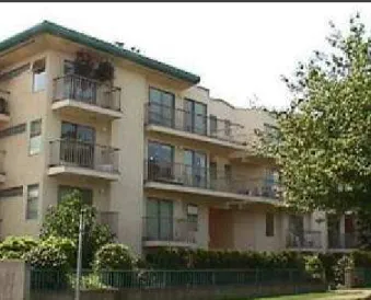
The building is a multi-unit three-storey residential wood-frame construction built about 1992. The second floor balcony is supported by exterior columns, while the third floor balcony is cantilevered. Water leakage to the interior of units following rain events was reported in some units and not others. Symptoms included wet carpets and moisture staining of ceiling finishes.
Site Observations and Discussion
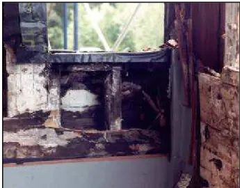
The aluminum siding was in good condition. The removal of cladding and sheathing membrane permitted the review and the mapping of staining patterns on the wood sheathing. These staining patterns were quite useful telltales of the path of water leakage (Figure 1). The wall sheathing had to be removed as well, to assess whether the stud cavity had suffered water damage. In many locations the structural framing exhibited serious deterioration and significant loss of structural integrity.Construction details were examined on site. There were no eave troughs on the sloped roof to direct water away from the walls and horizontal projections such as the balcony floors. This increased the water loads on protruding elements of the façade, such as the balconies. The detailing at the interface between the cantilevered balcony and the wall was such that water runoff from the wall above, as well as from the balcony deck, could penetrate to the stud cavity. MH investigators observed that external water had entered beyond the exterior cladding at the joint between the balcony and the wall. Openings for the cantilevered joists provided a moisture ingress path to the interior side of the sheathing membrane and to the stud cavity as well. The water then traveled by gravity to the horizontal framing at the second floor level where it moved laterally, causing significant damage across the balcony elevations. Detailing at the head of windows and patio doors also permitted water ingress, water trapping and/or water loading of other elements susceptible to moisture. The polyethylene wrap flashing at the head of these openings tended to trap moisture and rotting of wood-based materials at these locations was observed (Figure 2). The reverse lap of the sheathing membrane at the window head, the back slope on the drip flashing and absence of end dams (Figure 3) redirected water towards the jambs of the opening, leading to excessive wetting, as the staining pattern shows.
Ont a rio Ca se St udie s, by K e vin Chouina rd
Remedial Approach and Solutions
The remedial approach consisted of reducing the moisture loads on the façade elements by installing eave troughs on the sloped roof. As well, the detailing of the elements penetrating the exterior walls was modified to ensure the continuity of the second line of defence against rain penetration to provide positive drainage to the exterior (Figure 4). Pan flashings were integrated at the sill of windows and patio-door openings to minimize water ingress beyond the sheathing membrane. Saddle flashings were installed at the junction between the cantilevered joists and the wall to control this important water entry path in the existing construction.Lessons Learned
• Building drawings often lack sufficient detail for effective control of precipitation. Details therefore are left to the trades to provide on site during construction. Limited construction field review resulted in limited scrutinizing of these details in terms of water management ability and construction sequencing (e.g., shingle lapping of the sheathing membrane over the head flashing). • Ineffective detailing at cantilevered joists resulted in
extensive deterioration to the entire rear elevation, necessitating complete removal of cladding to effect repairs.
• The limited evidence of water leakage and damage to interior finishes was remarkable given the as-found condition of the wall framing outside of the polyethylene sheet vapour barrier. Extensive deterioration of the structural elements of the wall developed with few telltales on the interior or exterior of the assembly. • E ave troughs at sloped roofs reduced water load on
cladding and balconies.
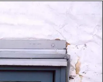
Figure 2. Window head detail showing the polyethylene wrap and the adjacent wood decay (as found).
Figure 3. Detail showing the reverse lap between the sheathing membrane and the flashing (as found).
Figure 4. Isometric view of the junction between the balcony joists and the exterior walls, as planned for the remedial work .
Ca se St udy N o. 2 :
Ra in Pe ne t ra t ion a t Junctions
Be t w e e n Pe ne t ra t ing
Ele m e nt s a nd t he Wa lls
Project History
The building is a four-storey multi-unit wood-frame residential building. The ground level is occupied by an open parking garage and the three levels above are residential units. Twelve years after construction, partial loss of support at a balcony prompted a detailed condition survey. Fifty percent of the balconies had to be closed due to loss of structural integrity.
Site observations and discussion
The aluminum siding and the exterior sheathing were removed. MH investigators observed extensive rot at the balcony elevations and particularly at the framing beneath cantilevered joists, and above and to the sides of window and door openings. In some locations significant loss of structural integrity had occurred.The elements to control rain penetration were either not in place or poorly detailed. The sheathing paper was completely missing in some wall areas – often limited to a horizontal strip above openings. The metal drip flashings above openings were typically nailed over the sheathing paper, causing a reversed lap situation and leading to water accumulation in the trough created by the polyethylene wrap. Flashings installed at the interface between balcony decks and the exterior walls were ineffective in preventing water entry past the sheathing membrane and permitted direct water entry to the stud space. In addition, the balcony-to-exterior wall junction was found to be typical at all locations, suggesting that this detail was either not recognized as inadequate by reviewers, or not reviewed at all.
Remedial Approach and Solutions
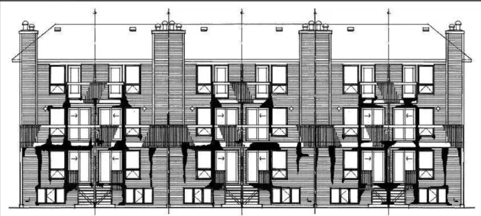
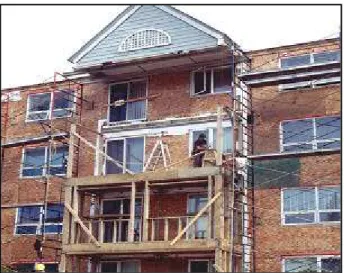
E xtensive reconstruction of the balcony elevations was required. Many of the cantilevered joists had to be replaced due to the extent of deterioration discovered to the inside of the wall sheathing (Figure 5). During remedial work, ledger boards were installed on vertical strapping to provide a cavity for drainage through the depth of the balcony deck. Sheathing membrane and metal flashings were provided as a second line of defence against water entry, and to facilitate drainage. Eave troughs were also installed to reduce the water load on the walls.Figure 5. E levation view of the housing project (during remedial work ).
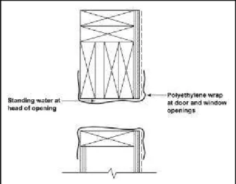
Figure 6. V ertical section showing the polyethylene wrap at window and door heads, acting as a trough for water accumulation (before remediation).
Lessons Learned
• Reversed lapping of elements leading water into an impermeable trough (i.e. polyethylene wrap at window heads) made adjacent moisture-sensitive elements prone to premature failure (Figure 6). Quality control over the construction sequencing of these elements is critical to their proper installation.
• The original aluminum siding was in remarkably good condition given the extent of damage behind – damage does not readily telegraph to the exterior surfaces, making discovery of such problems difficult.
• The conditions inboard of the polyethylene vapour barrier were found to be very good (i.e., deterioration was generally limited to the wood framing to the exterior of the polyethylene vapour barrier).
• Little attention appears to have been paid to detailing for water penetration control at the design stage for wood-frame residential buildings. Details were left to the builder’s discretion in the field.
•Site review by the design professionals requires scrutiny of details designed and/or selected by the builder.
Ca se St udy N o. 3 :
Conde nsa t ion in At t ic Spa c e
Project History
The residential complex is a 60-unit, 10-block townhouse development constructed circa 1980. The buildings are three-storey conventional platform wood-frame, with a combination of brick masonry and vinyl siding. Roofing has been redone recently. The moisture damage and staining were detected in the attics in the course of conducting local repairs. MH was retained to investigate the extent and cause of the problem. Mould was discovered in the course of conducting the review.
Site Observations and Discussion
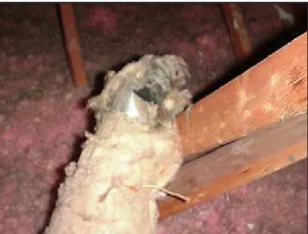
Mould growth varied from isolated colonies to extensive cover at the underside of roof sheathing (Figure 7). Significant decay of roof sheathing was observed in some units. The moisture content of the sheathing board and the truss framing was at less than 10% at the time of the investigation (September). Shingle fasteners were corroded on the inside of sheathing board.The MH investigation found that bathroom and clothes dryer exhausts discharged directly into attics (Figure 8). Attic ventilation was also very limited. Insulation had been blown in tightly against the eaves, restricting ventilation at the soffit, and mushroom vents were blocked at some locations. Uncontrolled air leakage was also observed at plumbing vent stacks, ceiling fixtures, bathroom fans, partition walls and other transition details. Polyethylene wrap at ceiling electrical fixtures was unsealed. Wetting of the sheathing board in cold weather resulted in deterioration and mould growth.
Remedial Approach and Solutions
The remedial work included:• E xhaust vent modifications to discharge directly to outside.
• Provision of attic ventilation.
• Local replacement of damaged roof sheathing; local repair to shingles and flashings.
• Installation or replacement of worn weatherstripping at attic hatches.
• Locating and sealing air barrier at penetrations through ceiling/attic floor. This necessitated local removal of attic insulation to allow visual review and air sealing where necessary.
Lessons Learned
• One must avoid exhausting indoor air to the attic space. • Attention must be paid to airtightness between living
and attic space.
• Penetrations are of particular concern and must be detailed for airtightness.
• E ave/soffit must be detailed and constructed to permit venting.
Figure 7. Deterioration and mould growth on the exterior sheathing facing the cold attic space (as found).
Figure 8. E xhaust fan duct discharged moisture into the attic space (as found).
Ca se St udy N o. 1 :
Ra in Pe ne t ra t ion
in Ex t e rior Wa lls
Project History
The building was a four-storey, wood-frame stucco clad condominium constructed in 1990. In plan, the building had four blocks linked together with exterior walkways (Figure 9). Other exterior features included cantilevered balconies, some walls with overhang protection and some without, and some walls without windows or balconies. There was a long history of water penetration including a repair program carried out in 1993, which included caulking, modifying deck membranes and coating the “concealed barrier” stucco with an elastomeric paint.
Site Observations and Discussion
A building envelope assessment was undertaken in late 1999. At that time, some major water entry points and material degradation were noted. This included buckling of stucco at floor plates, high moisture content in the sheathing detected by moisture probing and major degradation to sheathing and framing at test openings. A rehabilitation program including complete re-cladding was undertaken. During demolition the extent and severity of degradation was obvious. Much of the wall framing and floor framing had to be repaired or replaced.As typical in the BC coastal region, much of the degradation was associated with windows, exterior corners, junctions of exterior walls with balconies and walkways, mechanical vents and other such penetrations in walls. There was, however, major damage to walls that did not have windows or balconies (Figure 10). There was an interesting pattern of damage on these walls in that the sheathing on the top floor was typically in good condition but there was major degradation to the lower three floors (Figure 11).
It was suspected that a major reason for this pattern was the presence of two horizontal expansion joints in the stucco at each floor line. These joints were made with W-shaped beads and had been caulked at some point – perhaps in 1993. While the expansion joints may still have been water entry points, it seemed that one of the reasons for the decay pattern was that the joints restricted any drainage path between the building paper and stucco. This could have resulted in a pressure head to drive moisture past the building paper above the joints.
Remedial Approach and Solutions
This building underwent a major rehabilitation. All of the stucco was removed and the sheathing board replaced with treated plywood after required framing repairs. Windows were removed and rough openings re-detailed with a sub-sill flashing. Other details, including saddles, where balconies and walkways intersected with the walls and vent penetrations, were improved to minimize water penetration. The building was clad in a drained stucco system with a 19-mm cavity.Lessons Learned
This building confirmed the widely recognized and published conclusions about damage due to water intrusion in buildings in the Lower Mainland of British Columbia. It was clear that the source of water was rain and damage was generally associated with penetrations in the cladding such as windows, balconies and vents or highly exposed areas like corners. However, damage was not limited to those locations, showing that undrained stucco wall systems did not have sufficient water resistance to protect exposed walls in wet, coastal climates even in the absence of these problem elements. It is likely that the presence of horizontal expansion joints can compromise performance in such stucco systems by restricting drainage between the stucco and the building paper. Furthermore, this building shows that attempting to waterproof such undrained stucco buildings using elastomeric coatings and caulk is not a solution to water entry problems and may, in fact, accelerate decay.
We st Coa st Ca se St udie s, by M a rk La w t on
Figure 10. Severe damage to walls in areas remote from penetrations.
Figure 11. Horizontal joint may have restricted drainage from floor above.
Ca se St udy N o. 2 :
Air Le a k a ge int o Cold
Enc lose d Ca vit ie s
Project History
This project is a 25-year-old wood-frame, stacked townhouse complex with a “concealed barrier” stucco cladding with a rock dash finish. A key architectural feature was that the double stud party walls were expressed through the environmental separation in the form of dividing walls between balconies and curbed between sloped cathedral roofs (Figure 12).
A program of targeted envelope repairs was undertaken to address degradation associated with rain penetration particularly at penetration details, windows, etc. The extent of such damage was quite moderate considering the building’s age and recent experience in Vancouver.
Site Observations and Discussion
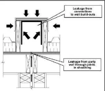
One unusual finding, and the focus of this case study, was the presence of widespread and significant decay associated with condensation of interior humidity rather than the intrusion of exterior moisture. This damage occurred to the exterior dividing walls and curbs on the roofs that were extensions of the double stud interior partition walls. Investigations found that there was no effective environmental separation at the junction of these elements at the plane of the exterior walls and the cathedral roof (Figure 13). There were large paths allowing air leakage and, for that matter, diffusion between the space in the double stud wall within the building to the enclosed space exposed on three to five sides to outdoor temperatures. In many of these areas there was mould growth, rot and degradation of the interior surfaces of the sheathing rather than the exterior (Figure 14).Remedial Approach and Solutions
The fundamental response to the damage found was to create environmental separation within the double stud walls at the plane of the exterior walls and cathedral roof. In a retrofit situation, this took some ingenuity and effort and use of a variety of materials. Strong reliance was placed on the use of spray urethane foam to create separations that provided some resistance to air leakage and vapour diffusion.Lessons Learned
The primary lesson from this case study is that condensation of interior moisture can create major areas of decay to buildings in temperate coastal climates. This is particularly true when indoor moisture is allowed to migrate into enclosed spaces with multiple exterior surfaces exposed to outdoor temperatures.
In this building, the damage was associated with the relatively unusual element of double stud walls and curbs expressed through the plane of the rest of the environmental separation. However, there are more common situations that create analogous circumstances. These include cantilevered balconies with unvented soffits and some parapet wall constructions. Providing vents to the exterior of enclosed spaces that may be connected to the indoor environment can be of some benefit, but should not replace the need for an appropriate environmental separation between inside and outside environments.
Ca se St udy N o. 3 :
Conde nsa t ion Da m a ge
on Ex t e rior She a t hing
Project History
This case study deals with one suite in a wood-frame stucco-clad townhouse development constructed about 1995. The complex was undergoing a targeted repair for rainwater intrusion problems.
Site Observations and Discussion
During demolition a location was exposed where there was degradation of the sheathing above a flange-mounted window on the third floor in a location well protected by an overhang. The OSB sheathing was covered by a layer of polymeric sheathing membrane and a “concealed barrier” stucco cladding system. The stucco terminated shortly above the window at the soffit line. The decay of the sheathing was primarily found on its outside face and was in a pattern consistent with the migration of moist air from inside upward between the sheathing and sheathing membrane (Figure 15).There was evidence that this suite had an unusually high interior humidity (evidence of window condensation and mould growth on the sheathing of the attic).
Remedial Approach and Solutions
Degraded materials were replaced and the window reinstalled with improved detailing to provide sub-sill flashing and an air seal located towards the interior of the window frame. Improvements to interior ventilation to control humidity were also put in place.Lessons Learned
This particular suite showed that air leakage through poorly sealed penetrations in walls can cause degradation to materials - at least in suites with elevated humidity. This reinforces the fact that control of air leakage remains a requirement in temperate coastal climates.
Figure 14. State of deterioration of the partition walls. Figure 13. L ack of control of airflow and moisture diffusion between the indoor spaces and a double stud partition leading to a cold roof cap.
Figure 15. Signs of damage on the sheathing board above the window, in a sheltered part of the exterior walls.
Ca se St udy N o. 1 :
Conde nsa t ion During
Const ruc t ion
Project History
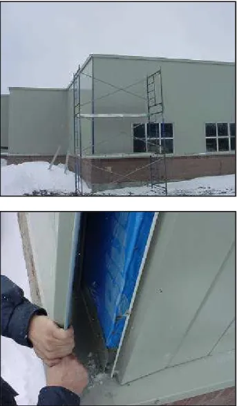
Widespread mould contamination was observed on the partially constructed wood-frame exterior walls of an institutional building following a Christmas construction shutdown. The building was being constructed in consecutive phases by several constructors with one contractor retained to complete the interior of the building after another contractor had completed the shell. The building is a 6000-square metre, structural steel frame building on concrete footings, with both wood-frame and concrete block infill walls. The wood-frame walls were to be insulated in the stud cavity and the concrete block walls were insulated on the exterior. The walls were clad with either metal siding or masonry veneer (Figure 16). The windows were thermally broken aluminum frame with sealed double-glazing. The insulated low-slope roofs included a two-ply modified bitumen roofing membrane. An elastomeric membrane air barrier was applied on the outside of the concrete block wall and on the exterior face of the wood-based sheathing board. Insulation was installed on the outside of the membrane on the concrete block walls. Neither the stud cavity insulation nor the vapour barrier had yet been installed on the wood-frame walls before the Christmas construction shutdown. The drawings and specifications described architectural details including those at wall-window junctions and at wall-roof junctions.
The contract to complete the interior of the building included casting concrete floors and laying up concrete block interior partitions. Construction started in September.
Site Observations and Discussion
Significant condensation was observed on the interior of the wood-frame wall sheathing while the interior of the building was being completed. The presence of condensation was coincident with the windows being closed in response to the arrival of colder weather. No supplemental heat source was installed in the building. After the Christmas shutdown, widespread mould contamination of the wood-frame sheathing was observed (Figure 17). The mould contamination occurred because of an excessive level of moisture indoors, which resulted in condensation on the colder exterior sheathing of the wood-frame walls. Indoormoisture levels were elevated because the construction process (i.e., casting concrete floors, installing concrete block partition walls) introduced moisture, which accumulated in the indoor space while no ventilation was in place to evacuate it outdoors.
Calculations show that a cubic metre of concrete contains 140 L of free water, and that a cubic metre of air at 10°C will hold 0.01 L of water. Air in the building became saturated with water from the concrete. It could not dry out by air leakage because of the effective air barrier system, or by vapour diffusion because of the vapour permeance of the sheathing, and ventilation was not available once the windows were closed.
At la nt ic Provinc e s Ca se St udie s, by Willia m C. Brow n
Figure 16. Building shell included windows and air barrier membrane installed on sheathing behind cladding.
Remedial Approach and Solutions
The remedial approach required that the mould contamination be removed and the water source be addressed. The owner elected to take down all wood-frame exterior walls, in order to remove the mould-contaminated materials – this also allowed the interior to dry. The walls were reinstated with new materials in a phased approach.Lessons Learned
• Buildings must function while under construction, as well as during operation.
• Moisture must be managed during construction, and effective management may require a working knowledge of psychrometrics.
• E xcess moisture can lead to mould contamination, even at colder surface temperatures.
• Mould remediation involves removing mould mass and eliminating the water source. It should be conducted by firms experienced in the field.
Figure 17. Widespread mould contamination observed on interior of sheathing.
Ca se St udy N o. 2 :
Rain Penetration at Balconies
Project History
A painting contractor reported soft spots in the siding/sheathing of a 38-unit, 3-½ storey, wood-frame townhouse complex about ten years after occupancy. Shortly after occupation, the owners had reported problems that included water penetration at windows and warping of cladding at balcony walls. Initial repairs were undertaken approximately five years after occupancy, which included sheathing replacement, framing repairs, and new cladding.
Site Observations and Discussion
In the original design, the exterior walls were finished with OSB sheathing, asphalt impregnated sheathing paper and cedar shingles adhered to thin plywood. The balconies were supported by framed walls with unprotected openings and covered by gable roof overhangs. The shingle/plywood cladding was fastened directly onto the balcony wall framing.Advanced wood rot was found in structural framing and sheathing throughout the balcony walls on both the east and west elevations, with more damage on the east elevation. Rot was present on framing and sheathing installed in the initial repairs, as well as on original construction materials. Deterioration appeared to progress from old material that had been left in place to new material; it was most severe at the bottom of the building. The patterns of rot indicated that rainwater and snowmelt were the source of moisture into the balcony and building walls.
Figure 18. E xtensive rot observed in walls below openings (as found).
In the initial repairs, the framed openings in the balcony walls were protected by wrapping the sills, jambs, and part of the head of each opening with a self-adhesive membrane. The framing and sheathing under this impermeable membrane exhibited a higher level of deterioration than adjacent materials (Figure 18).
Remedial Approach and Solutions
The balconies and their supporting walls had to be demolished and completely rebuilt because of the extent of structural damage (Figure 19). Pressure-treated material was utilized for all balcony framing components. Spun-bonded polyolefin building paper and aluminum flashing were installed at the head of all openings to direct water that passes the cladding back to the exterior. The shingles, sheathing paper, and sheathing on the building walls were removed to assess framing members. Rotted framing members were replaced with kiln-dried lumber. OSB sheathing was installed with spun-bonded polyolefin building paper, and vinyl siding was installed over semi-rigid insulation. Vinyl siding was chosen because of a ‘proven’ ability to control rain penetration, especially with the exposure to wind-driven rain at this site, and to address the owners’ request for amaintenance-free exterior.
Lessons Learned
• The extent of problems is often not evident from a visual survey.
• Building details must be designed and constructed to dissipate precipitation. Mock-ups and field review can help ensure that the design is constructed.
• Impervious membranes, when used inappropriately, can trap moisture, which increases the risk of deterioration.
• All rotting wood must be removed to eliminate the transfer of fungi to new material.
Ca se St udy N o. 3 : Ra in
Pe ne t ra t ion At Ba lc onie s
Project History
Rot was discovered in wall framing at a third-floor balcony during replacement of a patio door. The complex was about 9 years old and consisted of six three-storey blocks, each containing a number of two-storey townhouses and third-floor apartment ‘flats.’ Because of extensive damage to the structural framing, members had to be replaced and all third-floor balconies were closed until a more detailed assessment of the problem was completed.
Site Observations and Discussion
The buildings were built using conventional wood framing, with roofs that provided a 400-mm overhang. Third-floor balconies were nailed to rim joists and supported by ‘A’ frame brackets. Walls were clad with pine clapboard nailed over building paper and plywood sheathing. Corners were covered with pine boards and “water table” trim boards were installed along floor lines. Corner boards and “water table” trim boards, window casing and framing, and fascia boards were badly weathered, clapboards were cupped and did not lie flat against each other, and sealant joints were open at some locations. E xtensive rot was present in the framing below the ledger board, and the plywood sheathing below the balcony was often completely rotten (Figure 20). Water entered through the patio door assembly, between the patio doorsill and the top of the “water table” trim board, and over the ledger board because of a lack of flashing.Figure 19. Repairs involved replacement of large quantities of structural elements (during remedial work ).
Many windowsills were moisture damaged and there was rot immediately below window jambs and laterally along the wall at floor lines. Bulk water was often present on the bottom wall plates and the outside portions of sub-floors were often rotten. Water entered at the window jambs as well as between window units where exterior trim boards were installed without sealant, and directly into the wall cavity below these locations.
The sheathing board was stained at outside corners, and the sheathing and framing members just behind corner boards were rotten. The damage was comparatively less extensive than at the windows or at the balconies, probably because water that entered at the corners remained outboard of the building paper.
Remedial Approach and Solutions
Architectural details were developed to address the water management issues (Figure 21). The balconies were re-built (following removal of the siding and sheathing) and supported by new columns. The ledger board was installed on pressure-treated vertical strapping to create a drained air space between the ledger board and the building paper. A metal flashing started at the patio door sub-sill, overlapped the vertical strapping and terminated below the ledger board. In some areas, the wall framing had to be completely replaced, requiring shoring of the floor, and damage to the bearing ends of joists and the sub-floor required extensive interior work and disruption to occupants. Because the owner wanted to retain the original windows, which provided a water entry path into the wall assembly at corners, modifications were made to the exterior trim and sill extension and a sub-sill flashing was installed to manage water entry at the windows.Lessons Learned
• The extent of problems is often not evident from a visual survey.
• Balcony details must be designed and constructed to manage precipitation.
• Significant deterioration occurs where water penetrates beyond the sheathing membrane.
• The drainage plane should be shingle lapped and flashed to function effectively.
• Water leakage problems at window corners can be addressed by introducing a secondary protection against water ingress in the rough opening and adequate drainage to evacuate water down and out.
Figure 20. E xtensive damage discovered under windows and at balcony band joist.
Ca se St udy N o. 1 :
Ra in Pe ne t ra t ion a t t he
Wa ll/Window I nt e rfa c e
The investigation of buildings has shown that the detailing of the wall/window interface tends to be deficient in several ways:
• The continuity of the airtightness plane is not maintained.
• The sealant application does not conform to state-of-the-art practices to ensure performance and optimum service life.
• The rain penetration control strategies are based on a sole line of protection, at the exterior plane of the assembly.
These factors contribute to premature deterioration of the back-up wall, rotting of wood elements, corrosion of metals and the wetting of interior finishes.
Discontinuity of the Airtightness Plane
Figure 22 shows a detail that provides little control of air leakage at the wall/window interface. When the indoor air pressure is higher than the outdoor air pressure, warm humid air can exfiltrate and condense on its way out. When the air flow direction is reversed, air infiltration could occur, and in cold weather it would cool off the interior portion of the window frame below the dew point, resulting in the formation of dew, possibly mould growth on the interior, or frost in very cold weather. The solution consists of ensuring, by means of a sealant or an adhesive membrane, or spray-in-place low-density foam, the continuity of the air barrier system. The designer needs to have a clear intent of what elements of the wall are to act as part of the air barrier system, in the wall assembly as well as in the window assembly and must ensure that the two are connected in both structural and airtight manners.Sealant Configuration
In field investigations of buildings, it has been observed that a filet bead of caulking is applied at junctions between two external elements (Figure 23a). This seal is usually
intended to be the first line of defence (sometimes, the only one) against water ingress into the wall. A backer rod is usually not provided. Applying sealant in a filet bead configuration and without a backer rod tends to result in shear stresses within the sealant, while the sealant is designed to sustain tension and compression stresses. Shear stresses can shorten the service life of the sealant, due to cohesive failure. Once the seal has cracked, wind-driven rain can enter the wall assembly and cause damage. Investigations usually show that the clearance between the window frame and the rough opening is insufficient to apply a backer rod and sealant of sufficient width, based on its movement capability and expected displacement. Figure 23b shows that the width of the joint should be sufficient to accommodate differential movements without failure of the sealant. The joint should include a backer rod, in order to obtain the right seal shape, and to prevent three-sided adhesion.
Que be c Ca se St udie s, by A. Pa t e na ude
Figure 22. Detailing at the wall/ window interface resulting in air infiltration or air exfiltration.
Joint Between
Two Combination Windows
When several windows are joined together to make a larger one, a joint between the two coupling frame members is created (Figure 24a). This joint is typically caulked on-site, and/or covered by a moulding (Figure 24b). Rainwater can enter at the junction between the coupled frame elements by capillary action or as a result of an air pressure differential. This water leakage path can lead to damage to moisture-sensitive materials where water accumulates, e.g., on the window sill, inside the wall or on interior finishes.
To minimize that type of problem, several strategies are available. Joints between frames of combination windows can be designed to manage water entry. The designer can apply the rainscreen principle at that joint and obtain satisfactory performance. It involves providing a capillary break, an air barrier element, and a cavity for drainage and for pressure equalization (Figure 25). Composite windows with one monolithic frame do not present this difficulty as there is no coupling between two distinct framing elements.
A holistic approach to wall/window interface detailing consists of applying the rainscreen principle in that junction. This implies that all forces acting on the joints should be controlled, assuming that it is virtually impossible to eliminate all holes and imperfections in the external face of the joint. Figure 26 shows such an approach: • The continuity of the air barrier system is maintained. • Gravity drainage is facilitated by the placement of a
sloped sill and an air cavity, leading to external water evacuation (e.g., weep holes and flashing).
• Protection of the moisture-sensitive subsill is done by the installation of a water-resistant membrane. • Capillary action is minimized by making joints at least
10 mm wide.
• Air pressure differentials in the rough opening joint are minimized, because of the two-stage joint. The intermediate seal on the exterior face of the jambs and head should be more durable than the external seal, as it is protected from the direct weather exposure (e.g., wetting, ultraviolet radiation, extremes in thermal movements).
This approach to wall/window detailing should also be consistent with the rain penetration strategies applied in the field of the wall.
Figure 23a. E xample of poor sealant configuration at the external face of a wall/ window junction.
24b. Typical weatherproofing at the junction between the two jamb framing.
Figure 25. Features of a jamb connection between two combination windows for effective rain penetration contril. Figure 24a. Typical coupling between two single windows to mak e
Ca se St udy N o. 2
Conde nsa t ion on Window s
Condensation on windows can occur between multiple sashes of single glazing, or on the interior surface of a window unit. In both cases, the occupant’s visibility to the exterior becomes impaired, and dew or frost meltdown can lead to mould growth and premature deterioration of the surfaces where water accumulates.
Condensation Between Multiple
Sashes of Single Glazing
In cold weather, condensation will form on the interior face of the external glazing when the interior sash is not much more airtight than the external sash, and the indoor space is pressurized. Under these circumstances moist indoor air exfiltrates at imperfections in the interior set of sashes and condenses on the external set of sashes, which is colder (Figure 27). If the interior face of the external sash is below freezing, the moisture will deposit as frost, eventually melting and collecting on the sill, possibly leaking into the stud cavity. The pressurization of the indoor space can be due to stack effect (temperature difference between indoors and outdoors causing cold dry air to infiltrate in the lower parts of a building and
warm humid indoor to exfiltrate in the upper parts of a building), wind pressure or mechanical systems, and pumping action.
Investigations have shown that stack effect is a contributing factor to this problem, as it has been seen that the first floor of a two-storey house will not experience such type of condensation while the same type of windows located on the second floor will. However, little can be done
Figure 26. E xample of detailing of the wall/ window junction, based on the rainscreen principle.
Figure 27. E xfiltration of humid air leads to condensation or frost deposition on storm sash.
Figure 28 When the interior moisture loads are low, air tightening the interior sash and venting the outer storm sash will minimize the occurence of condensation.
about canceling stack effect, besides introducing a compensating mechanical system which would bring its own set of problems unless the air leakage of the window unit is minimized.
When the fogging or frosting on the glass and frame is either of short duration or of small coverage, the remedy can be limited to improving the airtightness of the interior sash and adjusting the venting of the external sash (Figure 28). When the problem is more severe, and has not been cured by this approach, the extra step may require increasing the temperature of the external glazing, so it remains above the dew point of the indoor air for longer periods. A major retrofit of the windows will be required, as the storm sash will have to be replaced by a double sealed glazing unit.
E xfiltration of warm and humid air can also occur in all discontinuities in the air barrier system of opaque parts of the walls. The only difference compared to what is happening on windows is that the condensate is hidden in the wall or roof spaces and may not be noticed for months
during cold weather. Nevertheless, the problem develops and degradation of materials and loss of performance is initiated. Frequently, problems become noticeable in the spring or during a spell of milder weather in mid-winter, where water will spill on interior finishes near the exterior walls, or signs of efflorescence will show on masonry, etc.
Condensation on the Interior
Surface of Windows
When dew or frost forms on the interior surfaces of windows, be it the sash or frame, or the glass area, it means that the temperature of these elements is too low for sustaining the current indoor relative humidity (RH) without condensation. These elements are at a temperature below the dew point temperature of the indoor air. Several factors can contribute to such problems, and the diagnostics of each case can be quite complex. Let’s examine the most common causes and remedies. Conditions that affect the temperature of the window elements are presented in Table 1.
Table 1. Causal factors for condensation on interior surfaces of windows
Causal factor related to the window
and wall characteristics Design consideration to avoid this problem
Condensation on the window frame:
Cold air infiltration at the junction between the window frame and the rough opening in the wall
Ensure the continuity of the air barrier system at the interface between the wall and the window.
Condensation on the window frame:
Thermal bridging between the warm interior elements of the windows with the cold exterior elements of the wall
• Select window profiles that will allow lining up the glazing and thermal break (when applicable) with the thermal insulation of the wall
• Insulate the joint at the wall/window interface
Condensation on window frame & sash:
• Cold air infiltration at the junction between an operable sash and the window frame.
• Thermal bridging effect at the junction between the glazing unit and the sash and/or between the sash and the frame
Condensation on the glazing:
Excessive heat loss by conduction at the perimeter of the glazing
This relates to the design of the window and the thermal properties of the materials used to make up
connections.
The contract specification for the selection of windows should include a requirement for condensation resistance, defined as the I index in the CSA A440-M00 standard. The level of condensation resistance required is based on the severity of the outdoor climate (i.e. design temperature 2.5% of the time), the indoor relative humidity and the indoor temperature.
Causal factors related to the operation
of the interior space Operation considerations to avoid this problem
Excessive humidity levels (see Table 2) • Better control over moisture sources
• Better control of the moisture evacuation and air exchange rate (ventilation)
Inadequate control of temperature at the interior face of the window
• Placement of heavy curtains and blinds preventing heat delivery to the window elements
• Blockage of heat registers by furniture
Table 2 provides a guideline on the maximum indoor relative humidity to prevent condensation in the centre of double glazed windows with free air circulation on the interior, as a function of outdoor temperature.1
Table 2. Maximum indoor relative humidity to prevent condensation in the center of double glazed windows
Conc lusion
E nsuring the continuity of heat, air, and moisture flow control strategies, particularly at junctions, and allowing for fast water drainage and evacuation promote long service life of exterior wall systems.
Outdoor Temperature Maximum Indoor Relative Humidity -28°C or less 15% -28°C to -23°C 20% -22°C to -17°C 25% -16°C to -12°C 30% -11°C to -6°C 35% -5°C to 4°C 40%
1 Canada Mortgage and Housing Corporation, Condensation in the Home: Where, Why, and What to Do about It,