HAL Id: hal-00708888
https://hal.archives-ouvertes.fr/hal-00708888
Submitted on 16 Jun 2012
HAL is a multi-disciplinary open access
archive for the deposit and dissemination of sci-entific research documents, whether they are pub-lished or not. The documents may come from teaching and research institutions in France or abroad, or from public or private research centers.
L’archive ouverte pluridisciplinaire HAL, est destinée au dépôt et à la diffusion de documents scientifiques de niveau recherche, publiés ou non, émanant des établissements d’enseignement et de recherche français ou étrangers, des laboratoires publics ou privés.
Process of Mapping between User Centric Concepts and
Lyee Internal Concepts
Selmin Nurcan, Mohamed Ben Ayed, Colette Rolland
To cite this version:
Selmin Nurcan, Mohamed Ben Ayed, Colette Rolland. Process of Mapping between User Centric Con-cepts and Lyee Internal ConCon-cepts. International Workshop on New Trends on Software Methodologies, Tools and Techniques (SoMET), Sep 2003, Stockholm, Sweden. pp.1-17. �hal-00708888�
Process of Mapping between User Centric
Concepts and Lyee Internal Concepts
Selmin NURCAN*+, Mohamed BEN AYED*, Colette ROLLAND*
(*)
Université Paris 1 - Panthéon - Sorbonne, CRI, 90, rue de Tolbiac 75634 Paris cedex 13 France (+)
IAE de Paris (Business Administration Institute), 21, rue Broca 75005 Paris France
Abstract. The overall objective of the research activity of the UP1 unit is to apply a method engineering approach to the Lyee methodology. This paper presents a
formalization of the Lyee Process Model using the concept of Map. It develops also two methodological guidelines supporting (i) the mapping of the Lyee user-centric requirements, which have been previously specified using Design Patterns, into Lyee software requirements and (ii) the optimization of the latter. The motivation is the search for efficiency and effectiveness in the formulation of requirements in accordance with the two levels Lyee Product Meta-Model. The pay-off will be a more productive process of requirements formulation and a better quality result.
1. Introduction
LyeeALL is a CASE environment which aims at transforming software requirements into code. These requirements are expressed in rather low-level terms such as screen layouts and database accesses. Moreover they are influenced by the LyeeALL internals such as the Lyee identification policy of program variables, the generated program structure and the Lyee program execution control mechanism. As a consequence, it is difficult to get the Lyee customer away from the burden of Lyee internals instead of focusing his/her attention on the requirements. The Sorbonne group develops research towards meeting this need. The overall objective of the research activity of the UP1 unit is to apply a method
engineering approach to the Lyee methodology. As a first step, the group is aiming at (1)
defining a user-centric requirements model; (2) developing methodological rules to support the capture of these requirements in a systematic way; (3) generating the Lyee software requirements from these user requirements. In a second step, the objective is to provide an intelligent software support for the elicitation of user centric requirements and the automated generation of the Lyee software requirements.
Any method is defined as composed of a product model and a process model [Prakash 99]. The product model defines the set of concepts, their properties and relationships that are needed to express the outcome of the process. The process model comprises the set of goals, activities and guidelines to support goal achievement and action execution. Our research approach is driven by these two elements, the Lyee product and process models.
• The Lyee requirements product model
We used a meta modelling approach to model (i) the set of concepts underlying the Lyee software requirements and (ii) to abstract from them the user-centric requirements model. The result of this effort is a 2-layer meta model. The upper layer corresponds to the user-centric requirements model whereas the lower layer identifies the set of concepts required to express software requirements in Lyee terms. We refer to those as Lyee user
requirements meta-model and Lyee software requirements meta-model respectively. These
• The Lyee requirements process model
As far as we are concerned with the Lyee process model, our aim is threefold:
(1) to systematise the capture of user-centric requirements and their formulation in terms which comply with the upper layer of the meta-model thanks to the design patterns, (2) to define rules for mapping to transform the set of Lyee requirements expressed with
the concepts of the upper layer of the meta-model into a set of equivalent requirements expressed in terms of the lower layer of the meta-model,
(3) to implement software tools to support the capture and formulation of these requirements, being Lyee user requirements and Lyee software requirements.
This paper is organized as follows. Section 2 defines Lyee Requirements Process Model. In order to formalize this Process Model, we use the MAP formalism which helps identifying the key process intentions and the possible strategies to achieve them. Section 3 develops one of the two alternative methodological guidelines to perform the mapping between the concepts of the Lyee user requirements meta-model and the ones of the Lyee
software requirements meta-model. Section 4 presents the methodological guideline
supporting the optimization of a given Process Route Diagram (PRD). Some idea of future work is given in the conclusion.
2. The Lyee Requirements Process Model
This section describes the Lyee Requirements Process Model using the MAP formalism. We first recall the Lyee Requirements Product Model and than present the Lyee Map.
2.1. Lyee Requirements Product Model
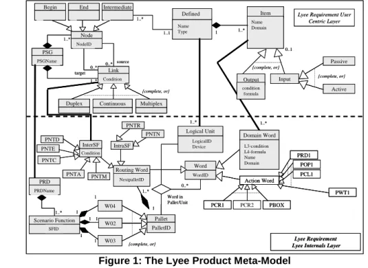
As presented in [Rolland 02a], [Rolland 02b], [Rolland 02c] and [Souveyet 02], the result of the conception effort for the Lyee product model is the two layers meta-model shown in Figure 1. This shows the Product Meta-Model1 and highlights the separation between the Lyee user requirements concepts and the Lyee software requirements concepts.
Lyee Requirement User Centric Layer
Lyee Requirement Lyee Internals Layer
1 1..* Name Domain {complete, or} Input Output source target Link Condition
Duplex Continuous Multiplex Name Type {complete, or} Node NodeID PSG PSGName 0..* 0..* Intermediate End Begin 1..* 1..1 1..* 1..* 1..* 1..* 0..1 {complete, or} Action Word W04 W02 W03 PNTR PNTD PNTE Logical Unit LogicalID Device SFID 1 1 1 1 1 1 1 1..* NextpalletID
Routing Word Word WordID Domain Word L3-condition L4-formula Name Domain PRD1 POP1 PCL1 PCR1 PCR2 PBOX PWT1 Word in Pallet/Unit 1..* InterSF PNTA PNTM IntraSF PNTN PNTC PRD PRDName Pallet PalletID Passive Active {complete, or} Item Defined condition formula Scenario Function Condition 0..*
Lyee Requirement User Centric Layer
Lyee Requirement Lyee Internals Layer
1 1..* Name Domain {complete, or} Input Output source target Link Condition Link Condition Duplex
Duplex ContinuousContinuous MultiplexMultiplex Name Type {complete, or} Node NodeID Node NodeID PSG PSGName PSG PSGName 0..* 0..* Intermediate Intermediate End End Begin Begin 1..* 1..1 1..* 1..* 1..* 1..* 0..1 {complete, or} Action Word W04 W02 W03 PNTR PNTD PNTE Logical Unit LogicalID Device SFID 1 1 1 1 1 1 1 1..* NextpalletID
Routing Word Word WordID Domain Word L3-condition L4-formula Name Domain PRD1 POP1 PCL1 PCR1 PCR2 PBOX PWT1 Word in Pallet/Unit 1..* InterSF PNTA PNTM IntraSF PNTN PNTC PRD PRDName PRD PRDName Pallet PalletID Pallet PalletID Passive Active {complete, or} Item Defined condition formula Scenario Function Condition 0..*
Figure 1: The Lyee Product Meta-Model
2.2. The Lyee Map
The Lyee Requirements Process Model is formalized as a Process Map with the key process intentions and the possible strategies to achieve them, and the associated guidelines. This section is organized as follows: Section 2.2.1 introduces the Process Meta-Model which allows us to specify the Lyee process model as a map. Section 2.2.2 describes broadly the Lyee process model, i.e. the Lyee Map. Section 2.2.3 introduces guidelines associated to the Lyee Map.
2.2.1. The Process Meta-Model
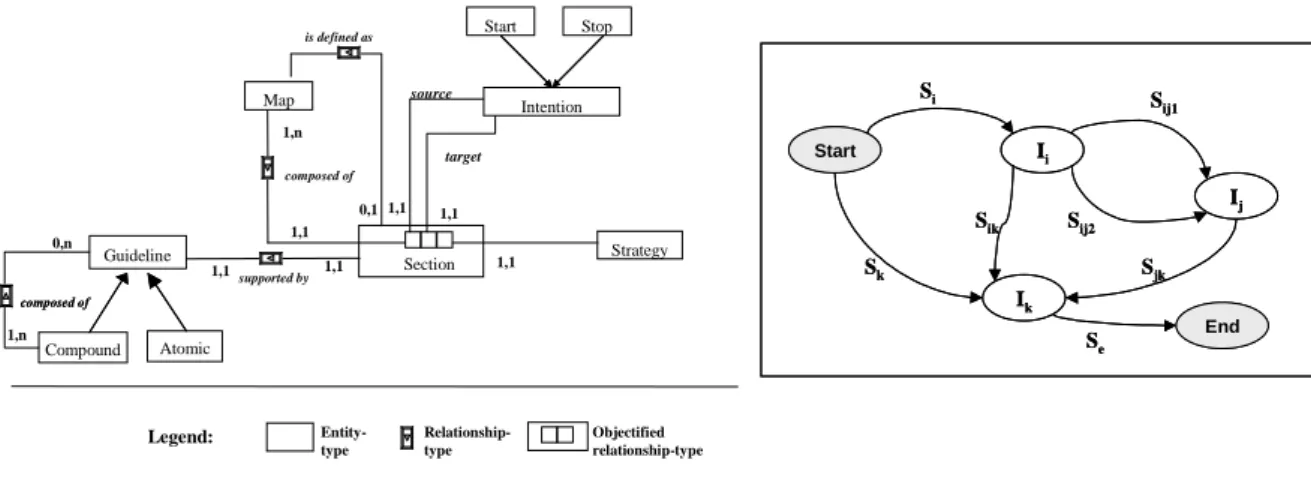
A map [Rolland 99], [Rolland 00], [Benjamen 99] is a process model in which a non-deterministic ordering of intentions and strategies has been included. It is a labeled directed graph with intentions as nodes and strategies as edges between intentions. As shown in Figure 22, a map consists of a number of sections each of which is a triplet <source intention I3i, target intention Ij, strategy S4ij>. There are two distinct intentions called Start
and Stop respectively that represent the intentions to start navigating in the map and to stop doing so. Thus, it can be seen that there are a number of paths in the graph from Start to
Stop. The map is a navigational structure that supports the dynamic selection of the
intention to be achieved next and the appropriate strategy to achieve it whereas the associated guidelines help in the achievement of the selected intention.
Map Start Stop Intention Section Strategy 1,1 1,1 source target 1,1 1,n composed of Legend: Entity-type Relationship-type Objectified relationship-type is defined as 0,1 Guideline Atomic Compound supported by composed of composed of 1,1 1,1 1,n 0,n 1,1 Start End Ij Ii Si S ij1 Sij2 Ik Sik Sk Se Sjk Start End Ij Ii Si S ij1 Sij2 Ik Sik Sk Se Sjk
Figure 2: The map meta-model
A strategy is an approach, a manner to achieve an intention. The strategy, as part of the triplet <Ii,Ij,Sij> characterizes the flow from Ii to Ij and the way Ij can be achieved. The specific manner in which an intention can be achieved is captured in a section of the map whereas the various sections having the same intention Ii as a source and Ij as target show
the different strategies that can be adopted for achieving Ij when coming from Ii. Similarly, there can be different sections having Ii as source and Ij, Ik, ....In as targets. These show the different intentions that can be achieved after the achievement of Ii.
There might be several flows from Ii to Ij, each corresponding to a specific strategy. In
this sense the map offers multi-thread flows. There might also be several strategies from different intentions to reach an intention Ii. In this sense the map offers multi-flow paths to achieve an intention. The map contains a finite number of paths, each of them prescribing a way to develop the product (a Lyee program), i.e. each of them is a Lyee process model.
2
We use an E/R like notation. A box represents en Entity Type (ET), the labeled link represents a Relationship Type (RT) and the embedded box refers to an objectified RT.
3
Intention are in italics (Ii, Ij)
4
Therefore the map is a multi-model. The approach suggests a dynamic construction of the actual path by navigating in the map. Because the next intention and strategy to achieve it are selected dynamically, guidelines that make available all choices open to handle a given situation are of great importance. The Lyee Map has such associated guidelines. A guideline is a set of indications on how to proceed to achieve an intention. A guideline embodies
method knowledge to guide the Lyee engineer in achieving an intention in a given situation.
The execution of each map section is supported by a guideline which can be atomic or compound. Some sections in a map can be defined as maps in a lower level of abstraction.
2.2.2. The Lyee process model or the Lyee Map
This section describes the Lyee process model by instantiating the concepts of the process meta-model presented in section 2.2.1. Figure 3 shows the Lyee process model, i.e. the Lyee Map. As shown in this figure, there are three key intentions in the Lyee process model, namely Capture Lyee User Requirements, Specify Lyee software requirements and
Generate Lyee program. We refer to them as ‘Process Intentions’. Capture Lyee User Requirements refers to all activities required to instantiate the upper level of the Product
Model for a given application whereas Specify Lyee software requirements refers to all those activities that are needed to map the concepts of the upper level of the Product Model into the concepts of the lower layer. Eight strategies are used in the Lyee Process Model.
A Lyee program can be generated following different paths in the Lyee Map, in other words, using several methodological approaches. For instance, the Lyee engineer can first follow the section <Start, Specify Lyee Software Requirements, From scratch strategy>, and then <Specify Lyee Software Requirements, Generate Lyee program, LyeeAll generation strategy>. The path including these two sections was documented in [Nurcan 02]. In this paper, we focus on the two map sections drawn in bold in Figure 3.
Start End Capture Lyee User Requirements Specify Lyee Sotware Requirements Generate Lyee Program From Scratch Strategy Design Pattern Driven strategy Optimisation Stategy LyeeALL Generation Strategy Completness Strategy Scenario Driven Strategy N to M Mapping Strategy Integrated Mapping Strategy Start End Capture Lyee User Requirements Specify Lyee Sotware Requirements Generate Lyee Program From Scratch Strategy Design Pattern Driven strategy Optimisation Stategy LyeeALL Generation Strategy Completness Strategy Scenario Driven Strategy N to M Mapping Strategy Integrated Mapping Strategy
Figure 3: The Lyee process model : the Lyee Map
2.2.3. The guidelines associated to the Lyee Map
The guideline corresponding to the map section <Start, Capture Lyee User Requirements, Design pattern driven strategy> was reported in [Rolland 02b], [Rolland 02d] and [BenAyed 03]. The two map sections <Capture Lyee User Requirements, Specify Lyee Software Requirements, Integrated mapping strategy> and <Capture Lyee User Requirements, Specify Lyee Software Requirements, N to M Mapping Strategy> describe
two alternative ways to transform a PSG (concept of the upper layer of the Lyee Product Model) into a PRD (concept of the lower layer of the Lyee Product Model).
The execution of the map section <Capture Lyee User Requirements, Specify Lyee Software Requirements, Integrated mapping strategy> transforms each Node (related to a Defined) in a given PSG into a Scenario Function in the corresponding PRD. The guideline associated to this map section will be described and illustrated in §3.
The execution of the map section <Capture Lyee User Requirements, Specify Lyee Software Requirements, N to M Mapping Strategy> transforms N Nodes (with their related Defineds) in a given PSG into M Scenario Functions in the corresponding PRD. The methodological knowledge supporting this map section was formally defined and illustrated in [BenAyed 03].
The execution of the map section < Specify Lyee Software Requirements, Specify Lyee Software Requirements, Optimisation strategy> aims to perform a set of optimization operations on the Lyee Software Requirements which are described by instantiation of the concepts of the Lyee Product Model’s lower layer. The guideline associated to this map section will be described and illustrated in §4.
3. The guideline supporting the map section <Capture Lyee User Requirements, Specify Lyee Software Requirements, Integrated Mapping strategy>
The aim of this section is to present the guideline associated to the map section <Capture Lyee User Requirements, Specify Lyee Software Requirements, Integrated Mapping Strategy> (see Figure 3), and the set of underlying mapping rules useful to establish the correspondence between the concepts of the two layers in the Lyee Product Meta-Model. Each mapping rule exploits the structural relationships between some concepts of the upper layer of the Product Meta-Model and some others in the lower layer (Figure 1). The guideline supporting the Map section <Capture Lyee User Requirements, Specify Lyee Software Requirements, Integrated Mapping Strategy> executes successively the following mapping rules for a given PSG in order to produce a PRD:
- Apply the mapping rule R0 to transform the PSG into a PRD,
- For each intermediate Node of the PSG: Apply the mapping rule R1S11 to transform
the Node into a Scenario Function in the corresponding PRD,
- For each Defined of the PSG: Apply the mapping rule R2S11 to transform the
Defined into one or several Logical Units in the Scenario Function; and to transform the items of the Defined into Domain Words shared by the Logical Units,
- Apply the mapping rule R3S11 to transform links between Nodes into InterSF
Routing Words,
- Apply the mapping rule R4 to add informations specific to the Lyee internal layer.
3.1. The Mapping Rule R0: Mapping a PSG into a PRD
In the Lyee process, each PSG is mapped into a PRD whatever the mapping strategy used. The mapping rule R0 performs the following actions: (i) Create a PRD corresponding to the PSG in hand and (ii) Define the PRD’s name.
3.2. The Mapping Rule R1S11 : Mapping a Node into a Scenario Function
The strategy of the Lyee Map presented in Section 3 is called Integrated Mapping because each Node in a given PSG is mapped into a Scenario Function. In other words, Integrated Mapping means “One to One mapping” for all Nodes. Figure 4 illustrates
graphically the ‘One to One Mapping’ strategy applied to two Nodes related to Defineds of type ‘screen’. W03 W02 W04 W02W02 W03W03 W04 W04 SF01 W03 W02 W04 W02W02 W03W03 W04 W04 SF02 END SW02 Sc2 SW02 Sc2 SR02 Sc2 SR02 Sc2 SW01 Sc1 SW01 Sc1 SR01 Sc1 SR01 Sc1 Physical Screen Ok Ok Defined Sc2 Ok Ok Defined Sc1 Cancel Cancel
Figure 4: The illustration of the ‘One to One Mapping’ strategy
In order to illustrate the Integrated Mapping Strategy, we use the ‘Split a Goal’ example. Split a Goal is a functionality which, given a goal statement such as ‘Withdraw
cash from an ATM’, automatically decomposes it into a verb and its parameters. For
example, Withdraw is the verb, cash is the target parameter of the verb and from an ATM is the means parameter. For this example, we will consider only the two parameters exemplified above, target and means.
Goal : Split Verb : Target : Means : Goal Split Cancel Goal : Split Verb : Target : Means : Goal Split Cancel
Figure 5: The user screen for the ‘Split a Goal’ example
:Active CmdCancel K :Output target X
target=ftarget(Split.goal)
:Output means X
means=fmeans(Split.goal)
:Defined Split screen :Passive Goal X :Active cmdSplit K :Continuous cmdCancel=true :Begin Node1 :Intermediate Node2 :End Node3 : PSG psgSplit :Continuous Source Target Source Target :Output verb X
verb=fverb(Split.goal)
:Active CmdCancel K :Active CmdCancel K :Output target X
target=ftarget(Split.goal)
:Output target X
target=ftarget(Split.goal)
:Output means X
means=fmeans(Split.goal)
:Output means X
means=fmeans(Split.goal)
:Defined Split screen :Defined Split screen :Passive Goal X :Passive Goal X :Active cmdSplit K :Active cmdSplit K :Continuous cmdCancel=true :Begin Node1 :Begin Node1 :Intermediate Node2 :Intermediate Node2 :End Node3 :End Node3 : PSG psgSplit : PSG PsgSplit :Continuous :Continuous Source Target Source Target :Output verb X
verb=fverb(Split.goal)
:Output verb X
verb=fverb(Split.goal)
Figure 6: Formulation of the user centric requirements for the ‘Split a goal’ example
Figure 5 shows the user screen designed for the ‘Split a Goal’ example. The Split button triggers the decomposition of the goal statement provided by the user in the Goal widget and the display of the result of this decomposition in the widgets verb, target and means. The Cancel button allows the user to stop the process at any moment.
Figure 6 presents the instance of the concepts in the upper layer of the Product Meta-Model created during the formulation of the user centric requirements for the given example. This instance is drawn using the UML object diagram notations. It shows that there is one PSG ‘PsgSplit’ which is composed of one Defined of type screen, namely ‘Split’, gathering the input and output items of the interaction. The ‘Split’ Defined comprises active items (cmdSplit and cmdCancel), output items (verb, target, means) and a passive item (Goal). Each output item in the Defined ‘Split’ is associated with a formula that is its calculation rule.
Mapping rule R1S11 5: An intermediate node in the upper layer is transformed into a
Scenario Function in the lower layer.
The mapping rule R1S11 performs the following actions for a given node in the PSG:
1. Create one SF for the intermediate node of the PSG; define SFID (concatenation of the string ‘SF’ and a sequential number),
2. Link the SF to the PRD (the one which has been created by the execution of the mapping rule)
3. Create the three pallets W04, W02 and W03,
4. Link the three pallets to the SF (Pallet belongs to SF)
5. For each pallet, define the PalletID (concatenation of SFID and the pallet name)
Example : The PSG ‘PsgSplit’ was previously transformed into the PRD ‘PrdSplit’ by the
application of the mapping rule R0. The intermediate node ‘Node2’ is transformed into the Scenario Function ‘SF01’ linked to the PRD ‘PrdSplit’. The three pallets ‘SF01W04’, ‘SF01W02’ and ‘SF01W03’ are created and linked to ‘SF01’, their PalletID are specified.
3.3. The Mapping Rule R2S11 : Mapping a Defined into Logical Unit(s)
Mapping rule R2S11 : A Defined is transformed into one or several Logical Units in the
Scenario Function created by the application of the mapping rule R1 S11 . The items of the Defined become Domain Words shared by the Logical Units.
A Defined is mapped into one or several Logical Units according to the Defined type. An Item is mapped into one or several Domain Words. These Words can belong to Logical Units in the same or in different Scenario Functions.
Let us consider an instance of PSG called PSGi6. The intermediate node of PSGi
(corresponding to the Defined in hand) has already been transformed into an instance of Scenario Function by the application of R1S11 . Let us call Definedj the Defined in hand.
The Scenario Function corresponding to the intermediate node of PSGj related to Definedj
is called SFj . The mapping rule R2S11 performs the following actions: • If the type of Definedj is ‘Screen’ :
1. Create two logical units SRj and SWj
2. Specify the LogicalID and the Device (Defined name) of SRji and SWj
3. For each input item in Definedj : (i) Create one instance of domain word, we call
it wordk (ii) Specify the name (item name) and the domain (item domain) of
wordk (iii) Associate the domain word wordk to the pallet W02 of the SFj and to
the SRj logical unit using a ternary relationship
4. For each output item in Definedj : (i) Create one instance of domain word, we
call it wordm (ii) Specify the name (item name), the domain (item domain), the
L4-formula (output item formula), and the L3-condition (item L3- condition), (iii) Associate the domain word wordm to the pallet W04 of the SFj and to the
SWj logical unit using a ternary relationship, (iv) Associate wordm to the pallet
W03 of the SFj and the to SWj logical unit using a ternary relationship. • If the type of Definedj is ‘Database’ :
5
This notation expresses that R1S11 is the first rule corresponding to the ‘Integrated mapping’ strategy. In fact, the
mapping rule R0 and R4 are also used when the ‘N to M mapping’ strategy is applied.
6 The sub-index letter is used to indicate an instance of a concept, for example Defined
j is an instance of concept Defined.
1. If there are input items in Definedj :
- Create one logical unit FRj
- Specify LogicalID and Device (Defined name) of FRj
- For each input item in Definedj : (i) Create a domain word, we call it wordk ,
(ii) Specify the name (item name) and the domain (item domain), (iii) Associate wordk to the pallet W02 of the SFj and the FRj logical unit using a
ternary relationship
2. If there are output items in Definedj :
- Create one logical unit FWj
- Specify LogicalID and Device (Defined name) of FWj
- For each output item in Definedj : (i) Create a domain word, we call it wordm ,
(ii) Specify the name (item name), the domain (item domain), the L4-formula (output item formula), and the L3-condition (item L3- condition), (iii) Associate wordm to the pallet W04 of the SFj and to the FWj logical unit, (iv)
Associate wordm to the pallet W03 of the SFj and to the FWj logical unit.
Example : Figure 7 shows the instances of the concepts of the Lyee internal layer of the
Product Meta-Model created by the application of the mapping rule R2S11 to the ‘Split a Goal’ example. The PSG ‘PsgSplit’ contains a single Defined ‘Split’ as shown in Figure 6.
The Defined ‘Split’ will be transformed into one or several Logical Units by the application of R2S11. The SF ‘SF01’ and the three pallets ‘SF01W02’, ‘SF01W03’ and ‘SF01W04’
were created by the transformation of the ‘Node2’ by applying R1S11.
:Domain Word
means X
means=fmeans(Split.goal)
:Output
target X
target=ftarget(Split.goal)
:Output
means X
means=fmeans(Split.goal)
:Defined Split screen :Passive Goal X :Output verb X
verb=fverb(Split.goal)
:Active cmdCancel K :Active cmdSplit K :W02 SF01W02 :W03 SF01W03 :W04 SF01W04 :Logical Unit SR01 Splitt :Logical Unit SW01 Split :Domain Word Goal X :Domain Word target X
target=ftarget(Split.goal)
:Domain Word
verb X
verb=fverb(Split.goal)
Instance of Lyee Requirements User Centric Layer Instance of Lyee Requirements Lyee Internal Layer :Domain Word cmdSplit K :Domain Word cmdCancel k :Scenario Function SF01 :Domain Word means X
means=fmeans(Split.goal)
:Domain Word
means X
means=fmeans(Split.goal)
:Output
target X
target=ftarget(Split.goal)
:Output
means X
means=fmeans(Split.goal)
:Defined Split screen :Defined Split screen :Passive Goal X :Passive Goal X :Output verb X
verb=fverb(Split.goal)
:Active cmdCancel K :Active cmdCancel K :Active cmdSplit K :Active cmdSplit K :W02 SF01W02 :W02 SF01W02 :W03 SF01W03 :W03 SF01W03 :W04 SF01W04 :W04 SF01W04 :Logical Unit SR01 Splitt :Logical Unit SR01 Splitt :Logical Unit SW01 Split :Logical Unit SW01 Split :Domain Word Goal X :Domain Word Goal X :Domain Word target X
target=ftarget(Split.goal)
:Domain Word
target X
target=ftarget(Split.goal)
:Domain Word
verb X
verb=fverb(Split.goal)
:Domain Word
verb X
verb=fverb(Split.goal)
Instance of Lyee Requirements User Centric Layer Instance of Lyee Requirements Lyee Internal Layer :Domain Word cmdSplit K :Domain Word cmdSplit K :Domain Word cmdCancel k :Domain Word cmdCancel k :Scenario Function SF01 :Scenario Function SF01
Figure 7 :The product resulting of the application of the mapping rule R2S11
to the ‘Split a Goal’ Example
3.4. The Mapping Rule R3S11 : transforming Links between Nodes into InterSF
Routing Words
Links between PSG Nodes are of three different types: Continuous, Duplex and
Multiplex.
Mapping rule R3S11 : Continuous, Multiplex or Duplex links between two Nodes are
transformed into InterSF Routing Words.
All links in the PSG becomes InterSF routing words in the corresponding PRD. The
word in the lower layer. The Duplex link in the upper layer of the meta-model matches up with the PNTD routing word in the lower layer. The Continuous link in the upper layer of the meta-model matches up with the PNTC, PNTA and PNTE routing words in the lower layer according to the situation.
Let us consider SFi and SFj, two Scenario Functions obtained by the transformation of
two nodes Ni and Nj when the rule R1S11 has been performed. Let us consider also that Ni
and Nj are respectively the source and the target nodes for a link Lij . We distinguish five
situations depending of the types of the link, of the source and target nodes in the PSG. According to the situation, the mapping rule R3S11 performs the following actions:
Situation 1: If the link Lij is of type Continuous and the target node is ‘End’:
- Create a PNTEi routing word, specify the WordID
- Specify NextPalletID of PNTEi (NextPalletID = End)
- Link PNTEi to the W03 pallet of SFi (corresponding to the source node)
Situation 2: If the linkLij is of type Continuous and the target node is related to a Defined
of type database:
- Create a PNTAi routing word, specify the WordID
- Specify NextPalletID of PNTAi (NextPalletID = Pallet W04 of SFj
corresponding to the target node)
- Link PNTAi tothe W03 pallet of SFi (corresponding to the source node)
Situation 3: If the linkLij is of type Continuous and the target node is related to a Defined
of type screen :
- Create a PNTCi routing word, specify the WordID
- Specify NextPalletID of PNTCi (NextPalletID = Pallet W04 of SFj
corresponding to the target node)
- Link PNTCi to the W03 pallet of SFi (corresponding to the source node)
Situation 4: If the linkLij is of type Multiplex :
- Create a PNTMi routing word, specify the WordID
- Specify NextPalletID of PNTMi (NextPalletID = Pallet W04 of SFj
corresponding to the target node)
- Link PNTMi to the W03 pallet of SFi (corresponding to the source node)
Situation 5: If the linkLij is of type Duplex :
- Create a PNTDi routing word, specify the WordID
- Specify NextPalletID of PNTDi (NextPalletID = Pallet W03 of SFj
corresponding to the target node)
- Link PNTDi to the W03 pallet of SFi (corresponding to the source node)
Example: The user centric requirements shown in Figure 6 includes two Continuous links.
The first Continuous link has ‘Begin’ as source node; this concept has not an equivalent in the lower layer, in fact the immediate start point of ‘PrdSplit’ is the pallet W04 of the Scenario Function SF01. The second continuous link has intermediate node ‘Node2’ as source and ‘End’ as target. SFi corresponds to ‘SF01’ according to R3S11. We are in the first
situation identified in this rule. Then we create a PNTE routing word and we link it to the W03 pallet of SF01.
3.5. The Mapping Rule R4 : Adding information specific to the Lyee internal layer
Some concepts of the lower layer of the meta model have no direct correspondence with the upper layer. These concepts are related to the Lyee knowledge and are necessary to
execute the Tense Control Function [Negoro01a], [Negoro01b], [BenAyed02], [Nurcan02]. Thus, the mapping rule supports the specifications of additional information specific to the Lyee Requirements of the Lyee Internal Layer.
Mapping rule R4: Add additional information specific to the Lyee Requirements of the
Lyee Internal Layer
The elements of the Lyee Internal Layer involved in this rule are IntraSF Routing Words (PNTR, PNTN) and Action Words ( PCR1, PCR2, PBOX, PWT1, PCL1, POP1, PRD1). The rule R4 performs the following actions (see [BenAyed 03] for more details):
1. Add one PNTR routing word to the W03 pallet of each Scenario Function SFi in the
PRD (the PRD was obtained by the transformation of the PSG in hand by the application of the mapping rule R0)
2. Add one PNTN routing word to the W04 pallet of each SFi in the PRD
3. Add one PNTN routing word to the W02 pallet of each SFi in the PRD
4. Add one or several Input Vectors to each Scenario Function SFi in the PRD
5. Add one or several Output Vectors to each Scenario Function SFi in the PRD
6. For each output Logical Unit LUi of the PRD (created by the transformation of the
PSG in hand by applying the rule R0), add Structural Vectors
Figure 8 shows the instances of the concepts of the Lyee internal layer of the Product Meta-Model created by the application of the mapping rules R3S11 and R4 to the ‘Split a Goal’
example.
:Domain Word target X
target=ftarget(Screen1.Goal)
:Domain Word verb X
verb=fverb(Screen1.Goal)
:Logical Unit SW01 Screen : PRD PrdSplit :Scenario Function SF01 :W04 SF01W04 :W03 SF01W03 :Domain Word means X
means=fmeans(Screen1.Goal)
:PCR1 PCR1SR01 :PCR2 PCR2SW01 :PBOX PBOXSR01 :PNTN PNTNSF01R4 SF01W02 :PNTN PNTNSF01R2 SF01W03 :PNTR PNTRSF01R3 SF01W04 :PNTE PNTESF01R3 END :Logical Unit SR01 Screen :W02 SF01W02 :Domain Word CmdCancel K :Domain Word CmdSplit K :Domain Word Goal X :PBOX PBOXSW01 :PRD1 PRD1SR01 :PWT1 PWT1SW01 :Domain Word target X
target=ftarget(Screen1.Goal)
:Domain Word target X
target=ftarget(Screen1.Goal)
:Domain Word verb X
verb=fverb(Screen1.Goal)
:Domain Word verb X
verb=fverb(Screen1.Goal)
:Logical Unit SW01 Screen :Logical Unit SW01 Screen : PRD PrdSplit : PRD PrdSplit :Scenario Function SF01 :Scenario Function SF01 :W04 SF01W04 :W04 SF01W04 :W03 SF01W03 :W03 SF01W03 :Domain Word means X
means=fmeans(Screen1.Goal)
:Domain Word means X
means=fmeans(Screen1.Goal)
:PCR1 PCR1SR01 :PCR1 PCR1SR01 :PCR2 PCR2SW01 :PCR2 PCR2SW01 :PBOX PBOXSR01 :PBOX PBOXSR01 :PNTN PNTNSF01R4 SF01W02 :PNTN PNTNSF01R4 SF01W02 :PNTN PNTNSF01R2 SF01W03 :PNTN PNTNSF01R2 SF01W03 :PNTR PNTRSF01R3 SF01W04 :PNTR PNTRSF01R3 SF01W04 :PNTE PNTESF01R3 END :PNTE PNTESF01R3 END :Logical Unit SR01 Screen :Logical Unit SR01 Screen :W02 SF01W02 :W02 SF01W02 :Domain Word CmdCancel K :Domain Word CmdCancel K :Domain Word CmdSplit K :Domain Word CmdSplit K :Domain Word Goal X :Domain Word Goal X :PBOX PBOXSW01 :PBOX PBOXSW01 :PRD1 PRD1SR01 :PRD1 PRD1SR01 :PWT1 PWT1SW01 :PWT1 PWT1SW01
Figure 8 : The product resulting of the application of the mapping rules R3S11 and R4
to the ‘Split a Goal’ Example
4. The guideline supporting the map section < Specify Lyee Software Requirements, Specify Lyee Software Requirements, Optimization strategy>
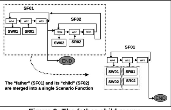
This section presents the guideline associated to the map section <Specify Lyee Software Requirements, Specify Lyee Software Requirements, Optimization strategy> (see Figure 3). The optimization of a PRD consists in transforming (merging) successively two or several Scenario Functions into single ones. Two merge tactics are proposed, respectively ‘Father-Child Merge’ and ‘Brotherhood Merge’. For a given PRD, these two tactics can be used in an intertwined manner.
4.1. The Father-Child merge tactics
The ‘Father-Child merge’ term means that two Scenario Functions SFi and SFj related
with a Continuous link are merged into a single Scenario Function. In addition, let us specify that the Scenario Function SFi is not the source of a backward link (multiplex or
duplex). In this case, SFi is called the Father Scenario Function and SFj is called the Child
Scenario Function. This tactics is applicable:
(i) in the situations where the external environment or the user requirements impose one physical screen to the Human Computer Interface; in this case the father and child Scenario Functions are related to Defineds of type ‘screen’;
(ii) in the situations where optimization considerations require a set of clustered database accesses and where database distribution considerations allow that; in this case the father and child Scenario Functions are related to Defineds of type ‘database’.
W03 W02 W04 SF01 W03 W02 W04 SF02 END SW02 SR02 SW01 SR01 W03 W02 W04 END
The “father” (SF01) and its “child” (SF02) are merged into a single Scenario Function
SF01 SW01 SW02 SR01 SR02 W03 W02 W04 W02W02 W03W03 W04 W04 SF01 W03 W02 W04 W02W02 W03W03 W04 W04 SF02 END SW02 SR02 SW01 SR01 W03 W02 W04 W02W02 W03W03 W04 W04 END
The “father” (SF01) and its “child” (SF02) are merged into a single Scenario Function
SF01
SW01 SW02
SR01 SR02
Figure 9: The father-child merge
The tactics can be applied successively several times to perform the merging between several Scenario Functions which are in sequence in the PRD. Figure 9 presents two PRDs, respectively before and after the optimization strategy being applied using the ‘Father-Child merge’ tactics. This figure presents the two PRDs and the related SFs using the Lyee community notations. The ‘father’ Scenario Function ‘SF01’ and the ‘child’ Scenario Function ‘SF02’ are merged in a single Scenario Function called ‘SF01’.
4.1. 1 Example of Father-Child merge
In order to illustrate this optimization rule, we make use of a variant of the ‘Split a
Goal’ example. Goal : Split Cancel Goal : Split Goal : Split Cancel Screen “Sc1” Verb : Target : Means : Goal Split Stop Return Verb : Target : Means : Goal Split Stop Return Screen “Sc2”
Figure 10: The user screens for the ‘Split a goal’ example W03 W02 W04 SF01 W03 W02 W04 SF02 END SW02 SR02 SW01 SR01 Sc1 Sc2 W03 W02 W04 W02W02 W03W03 W04 W04 SF01 W03 W02 W04 W02W02 W03W03 W04 W04 SF02 END SW02 SR02 SW01 SR01 Sc1 Sc2
Figure 11 : The PRD of ‘Split a Goal’ example
The PRD corresponding to the ‘Split a Goal’ example is shown in Figure 11.
Let us suppose that, thanks to the Design Patterns, the user interactions have been initially designed as requiring two Defineds of type screens. Figure 10 shows the two screens of the adopted variant of the ‘Split a Goal’ example: the Split button triggers the decomposition of the goal statement provided by the user in the Goal widget and its display in the widgets verb, target and means. The Cancel button allows the user to stop the process at any moment. The Split button triggers the decomposition of the Goal. The Stop button ends the interaction with the user.
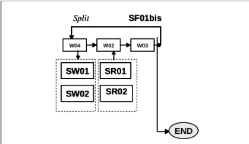
Let us now assume that user requirements impose the use of a single physical screen to support the ‘Split a goal’ example. Consequently, screens ‘Sc1’ and ‘Sc2’ should be merged in the single screen ‘Split’. Figure 12 shows this screen. The application of the father-child optimization rule will produce the PRD shown in Figure 13.
Goal : Split Verb : Target : Means : Goal Split Stop Cancel Return Goal : Split Verb : Target : Means : Goal Split Stop Cancel Return
Figure 12 : The user screen for the ‘Split a goal’ example
W03 W02 W04 END SF01bis SW01 SW02 SR01 SR02 Split W03 W02 W04 W02W02 W03W03 W04 W04 END SF01bis SW01 SW02 SR01 SR02 Split
Figure 13 : The ‘Optimized PRD’ for the ‘Split a Goal’ example
4.1.2. Optimization rule for the ‘Father-child merge’ tactics
This rule performs the following set of actions for a given couple of Scenario Functions (SFf, SFc) identified as candidate to the father-child merge in the given PRDi. We consider
SFf as ‘Father’ Scenario Function and SFc as ‘Child’ Scenario Function. SFk is the Scenario
Function produced by the application of the optimization rule.
1. Create one Scenario Function SFk, define SFID 2. Link SFk to the PRDi.
3. Create the three Pallets W04, W02 and W03
4. Link the three pallets to SFk 5. For each pallet, define the PalletID
6. Copy InterSF routing words related to the pallets W03 of SFf and SFc to the pallet
W03 of SFk, The InterSF routing word corresponding to the continuous, multiplex
or duplex link between SFf and SFc should be deleted.
7. Each InterSF routing word in the PRD having SFf or SFc as target should be
modified :
- if routing word type is PNTC, PNTA or PNTM then NextPalletID = Pallet W04 of SFk
- if routing word type is PNTD then NextPalletID = Pallet W03 of SFk
8. Logical units and words related to the Scenario Functions SFf and SFc are linked to
the corresponding pallets of the Scenario Function SFk.
- Copy and link input logical units and the related words to the W02 pallet of the Scenario Function SFk using a ternary relationship
- Copy and link output logical units and the related words to the W04 and the W03 pallets of the Scenario Function SFk using a ternary relationship. 9. Add additional information specific to the Lyee internal layer7
a) Add one PNTR routing word to the W03 pallet of the Scenario Function SFk,
specify NextpalletID as Pallet W04 of SFk
b) Add one PNTN routing word to the W04 pallet of SFk, specify NextpalletID as
Pallet W02 of SFk
c) Add one PNTN routing word to the W02 pallet of SFk, specify NextpalletID as
Pallet W03 of SFk
d) Add Input Vectors to the Scenario Function SFk
e) Add Output Vectors to the Scenario Function SFk
f) For each output Logical Unit LUi related to SFk add Structural Vectors
10. Delete the Scenario Functions SFF and SFC and their related logical units and words.
The application of this rule for the PRD of the ‘Split a goal’ example shown in Figure 11 produces the PRD shown in Figure 13. The Scenario Functions SF01 and SF02 are merged into a single Scenario Function ‘SF01bis’. The input logical units ‘SR01’ and
‘SR02’ are added to W02 pallet of ‘SF01bis’. The output logical units ‘SW01’ and ‘SW02’
are added to W04 pallet of ‘SF01bis’.
4.2. The Brotherhood merge tactics
The ‘Brotherhood merge’ means that N scenarios functions having the same source Scenario Function SFi in N Continuous Links for which they are targets are merged into a
single Scenario Function. In addition, let us specify that the source Scenario Function SFi is
not the source of any backward link (multiplex or duplex). This tactics is applicable:
(i) in the situations where the external environment or the user requirements impose one physical screen to the Human Computer Interface; in this case the brotherhood Scenario Functions are related to Defineds of type ‘screen’;
(ii) in the situations where optimization considerations require a set of clustered database accesses and where database distribution considerations allows that; in this case brotherhood Scenario Functions are related to Defineds of type ‘database’.
Figure 14 illustrates graphically the ‘brotherhood merge’ tactics. The tactics can be applied successively several times to perform the merging of several set of brotherhood Scenario Functions.
The “brothers” SF02 and SF03 are merged into a single Scenario Function
W03 W02 W04 SF01 W03 W02 W04 END SW01 SR01 SW02 W03 W02 W04 SR02 SF02 SF03 SW03 SR03 W03 W02 W04 SW02 SR02 SF02 condition1 condition2 SW03 SR03 The “brothers” SF02 and SF03 are merged into a single Scenario Function
W03 W02 W04 W02W02 W03W03 W04 W04 SF01 W03 W02 W04 W02W02 W03W03 W04 W04 END SW01 SR01SR01 SW02 SW02 W03 W02 W04 W02W02 W03W03 W04 W04 SR02 SR02 SF02 SF03 SW03 SW03 SR03SR03 W03 W02 W04 W02W02 W03W03 W04 W04 SW02 SR02 SF02 condition1 condition2 SW03 SW03 SR03
Figure 14 : The brotherhood merge 4.2.1 Example of Brotherhood merge
In order to illustrate the optimization rule we defined for the ‘Brotherhood merge’ tactics, we use the ‘Room booking’ example. Room Booking is a functionality of a traveller support system which helps the users of the system to make hotel room reservations for the
customers according to their specific needs. The database includes information about customers and rooms offered for booking. The system shall let the user state his/her booking requirements in terms of date (beginning and ending dates of the booking period), as well as location of the hotel (name of the city in which the hotel shall be chosen), and category of the hotel (expressed as a number of stars).
Let us suppose that, for implementing the ‘room booking’ functionality, the user interactions have been initially designed as requiring three Defineds of type screens as shown in Figure 15. The user specifies the customer for which the booking is recorded, and the booking requirements for a room (booking dates, location, and desired hotel category). When the OK button is pressed, the system checks first if the customer exists. For an unknown customer, the ‘customer error message’ is displayed in an output screen. If the customer exists, the system checks the availability of a room satisfying the customer’s requirements. If there is no available room which meets the customer’s requirement, the ‘Not Available Room’ error message is displayed in a second output screen. The Cancel button allows the user to stop the process at any moment. The Stop button ends the interaction with the user.
Customer Begindate Enddate Room Booking City Stars Ok Cancel Customer Begindate Enddate Room Booking City Stars Ok Cancel
Customer existence error Message
Return Stop
Customer existence error Message
Return Stop
CustomerError Message
No Available room error Message
Return Stop
No Available room error Message
Return Stop
Not Available Room Error Message
Figure 15: The user screens for the ‘Room booking’ example
The PRD corresponding to the ‘Room booking’ example obtained by the execution of the map section <Capture Lyee User Requirements, Specify Lyee Software Requirements, Integrated Mapping Strategy> is shown in Figure 16.
W04 SF01 SW01 SR01 Sc1 W02 W03 W04 SF02 W02 W03 FR01 W04 SW02 SR02 Scase1 W02 W03 W04 SW03 SR03 Scase2 W02 W03 End CmdCancel=true ∃∃∃∃Customer No Available room SF03 SF04 W04 SF01 SW01 SR01 Sc1 W02 W03 W04 SF02 W02 W03 FR01 W04 SW02 SR02 Scase1 W02 W03 W04 SW03 SR03 Scase2 W02 W03 End CmdCancel=true ∃∃∃∃Customer ∃∃∃∃Customer No Available room SF03 SF04
Figure 16 : The PRD of ‘Room booking’ example
Let us now assume that user requirements impose the use of a single physical screen to support the ‘error messages’. Consequently, screens ‘Scase1’ and ‘Scase2’ should be merged in the single screen. Figure 17 shows this screen.
Customer existence error Message
Return Stop
No Available room error Message
Return Stop
Customer existence error Message
Return Stop
No Available room error Message
Return Stop
Figure 17 : The user screen For the two error messages
W04 SF01 SW01 SR01 Sc1 W02 W03 W04 SF02 W02 W03 FR01 W04 SW02 SR02 Scase W02 W03 End CmdCancel=true
∃∃∃∃Customer or No Available room
SF03bis SW03 SR03 W04 SF01 SW01 SR01 Sc1 W02 W03 W04 SF02 W02 W03 FR01 W04 SW02 SR02 Scase W02 W03 End CmdCancel=true
∃∃∃∃Customer or No Available room
∃∃∃∃Customer or No Available room
SF03bis
SW03 SR03
Figure 18 : The ‘Optimized PRD’ for the ‘Room booking’ example
4.2.2. Optimization rule for the ‘Brotherhood merge’ tactics
This rule performs the following set of actions for a given set of brotherhood Scenario Functions SFj identified as candidate to the brotherhood merge in the given PRDi. We
consider SFi as the source Scenario Function in the N Continuous Links for which the
brotherhood Scenario Functions SFj are targets. SFk is the Scenario Function produced by
the application of the rule to the brotherhood Scenario Functions SFj. 1. Create one Scenario Function SFk, define SFID
2. Link SFk to the PRDi.
3. Create three Pallets W04, W02 and W03.
4. Link the three pallets to the SFk 5. For each pallet, define the PalletID
6. Copy InterSF routing words related to the W03 pallet of each SFj to the W03 pallet
of SFk. The InterSF routing word corresponding to the continuous, multiplex or
duplex link between SFf and SFc should be deleted.
7. Each InterSF routing words in the PRD which have SFf or SFc as target should be
modified (same sub-actions than in the Father-Child merge)
8. Logical units and words related to each Scenario Function SFj are linked to the
corresponding pallets of the Scenario Function SFk (same sub-actions than in the Father-Child merge)
9. Add additional information specific to the Lyee internal layer (same sub-actions
than in the Father-Child merge)
10. Delete all Scenario Functions SFj and their related logical units and words.
The application of this rule for the PRD of the ‘Room booking’ example shown in Figures 15 and 16 produces the PRD shown in Figure 18. The Brotherhood Scenario Functions ‘SF03’ and ‘SF04’ are merged into a single Scenario Function ‘SF03bis’. The input logical units ‘SR02’ and ‘SR03’ are added to W02 pallet of ‘SF03bis’. The output logical units ‘SW02’ and ‘SW03’ are added to W04 pallet of ‘SF03bis’.
4.3. The guideline associated to the Map section
The guideline associated to the Map section <Specify Lyee Software requirement, Specify Lyee Software requirement, Optimization strategy> implements the following optimization rules:
For each set of Scenario Functions in a PRD describing an atomic interaction (see
[Rolland02d])
For each set of SFs candidates to a brotherhood merge
List the brotherhood SFs to the user
If requested Apply the ‘Brotherhood Merge’ tactics for these SFs For each set of SFs candidates to a Father-child merge
List the couple of SFs to the user
If requested Apply the ‘Father-Child Merge’ tactics 5. Conclusion
We presented in this paper a formalization of the Lyee Process Model using the concept of Map. We also developed two methodological guidelines associated to two sections of the Lyee Map, respectively <Capture Lyee User Requirements, Specify Lyee Software Requirements, Integrated Mapping Strategy>, <Specify Lyee Software requirements, Specify Lyee Software requirements, Optimization strategy>.
For a given PSG, the mapping between the concepts of the Lyee user requirements
meta-model and the Lyee software requirements meta-model can be performed in two
alternative ways, following one of the two sections of the Lyee Map, namely <Capture Lyee User Requirements, Specify Lyee Software Requirements, Integrated Mapping Strategy> and <Capture Lyee User Requirements, Specify Lyee Software Requirements, N to M Mapping Strategy>. The guideline associated to the former allows us to generate automatically a PRD from a PSG. Experimentation with various examples shown that the mapping is possible by following the rules presented in Section 3. The result is however a PRD that could be transformed to support improvements. Furthermore, the second guideline presented in this paper implements the PRD optimization strategy.
Still now, we defined the guidelines which support the execution of the map sections. The Lyee process knowledge should be completed in order to guide the Lyee engineer to choose between two alternative sections from a source intention towards a target intention in the Lyee Map. This type of guideline, describing how other guidelines should be applied is required, for instance, to guide the selection of one of the two strategies, Integrated
Mapping and N to M Mapping during the execution of the Lyee Map.
The future work includes the following tasks: (i) to develop a software support for the elicitation of the user centric Lyee requirements and the automated generation of the Lyee software requirements; (ii) to define the methodological guidelines supporting the navigation in the Lyee Map and to offer an automatic support for their execution.
6. References:
[Alexander 77 ] C. Alexander, S. Ishikawa, M. Silverstein, M. Jacobson, I. Fiksdahl-King, S. Angel, ‘A
Pattern Language’, Oxford University Press, New York, 1977.
[Benjamen 99] A. Benjamen, “Une Approche Multi-démarches pour la modélisation des demarches
méthodologiques”, Ph. D thesis, University Paris1.
[BenAyed 02] M. BenAyed, "Lyee Program Execution Patterns". Proceeding of Lyee-W02: New Trends in Software Methodologies, Tools and Techniques, pp 212-224, Paris, 2002.
[BenAyed 03] M. Ben Ayed, S. Nurcan, “Technical Report TR2-1”, Lyee International Research Project, University Paris1, 2003.
[Coplien 95] J. Coplien, D. Schmidt (eds.), “Pattern Languages of Program Design”, Addison Wesley, Reading, MA, 1995.
[Gamma 95] E. Gamma, R. Helm, R. Johnson, J. Vlissides, “Design Patterns : Elements of Reusable Object
[Negoro 01a] F. Negoro, “Methodology to Determine Software in a Deterministic Manner”, Proceeding of ICII, Beijing, China, 2001.
[Negoro 01b] F. Negoro, “A proposal for Requirement Engineering”, Proceeding of ADBIS, Vilnius, Lithuania, 2001.
[Nurcan 02] S. Nurcan, M. BenAyed, C. Rolland, “Scientific Report Sc1”, Lyee International Research Project, University Paris1, 2002.
[Prakash 99] N. Prakash, “On Method Statics and Dynamics”, Information Systems, Vol 24, No 8, pp 613-637, 1999.
[Rolland 99] C. Rolland, N. Prakash, A. Benjamen, “A Multi-Model View of Process Modelling”, Requirements Engineering Journal, Vol 4, No 4, 169-187, 1999.
[Rolland 00] C. Rolland et al., “Bridging the Gap Between Organizational Needs and ERP Functionality”, Requirement Engineering, pp. 180-193, Springer-Verlag London Limited, 2000.
[Rolland 02a] C. Rolland, M. Ben Ayed, "Understanding the Lyee Methodology through Meta Modelling", Proceeding of EMMSAD, Toronto, 2002.
[Rolland 02b] C. Rolland, “A User Centric View of Lyee Requirement”, Proceedings of Lyee-W02: New Trends in Software Methodologies, Tools and Techniques, pp 155-169, Paris, 2002.
[Rolland 02c] C. Rolland, C. Souveyet, M. Ben Ayed, "Users Requirements Elicitation in the Lyee Software
Factory". Proceeding of SCI, Orlando, 2002.
[Rolland 02d] C. Rolland, “Technical Report TR1-2”, Lyee International Research Project, University Paris1, 2002.
[Souveyet 02] C. Souveyet, C. Salinesi, “Generating Lyee Program from User Requirements with a
Meta-Model based Methodology”, Proceedings of Lyee-W02: New Trends in Software Methodologies, Tools