HAL Id: hal-00298945
https://hal.archives-ouvertes.fr/hal-00298945
Submitted on 15 Apr 2008HAL is a multi-disciplinary open access
archive for the deposit and dissemination of sci-entific research documents, whether they are pub-lished or not. The documents may come from teaching and research institutions in France or abroad, or from public or private research centers.
L’archive ouverte pluridisciplinaire HAL, est destinée au dépôt et à la diffusion de documents scientifiques de niveau recherche, publiés ou non, émanant des établissements d’enseignement et de recherche français ou étrangers, des laboratoires publics ou privés.
Dye staining and excavation of a lateral preferential flow
network
A. E. Anderson, M. Weiler, Y. Alila, R. O. Hudson
To cite this version:
A. E. Anderson, M. Weiler, Y. Alila, R. O. Hudson. Dye staining and excavation of a lateral preferential flow network. Hydrology and Earth System Sciences Discussions, European Geosciences Union, 2008, 5 (2), pp.1043-1065. �hal-00298945�
HESSD
5, 1043–1065, 2008 Excavation of a lateral preferential flow network A. E. Anderson et al. Title Page Abstract Introduction Conclusions References Tables Figures ◭ ◮ ◭ ◮ Back CloseFull Screen / Esc
Printer-friendly Version
Interactive Discussion
Hydrol. Earth Syst. Sci. Discuss., 5, 1043–1065, 2008 www.hydrol-earth-syst-sci-discuss.net/5/1043/2008/ © Author(s) 2008. This work is distributed under the Creative Commons Attribution 3.0 License.
Hydrology and Earth System Sciences Discussions
Papers published in Hydrology and Earth System Sciences Discussions are under open-access review for the journal Hydrology and Earth System Sciences
Dye staining and excavation of a lateral
preferential flow network
A. E. Anderson1, M. Weiler2, Y. Alila3, and R. O. Hudson4
1
Sustainable Resource Development, Calgary, Alberta, Canada
2
Institute of Hydrology, Albert-Ludwigs University, Freiburg, Germany
3
Department of Forest Resources Management, University of British Columbia Vancouver, British Columbia, Canada
4
Adjunct Professor, Department of Forest Resources Management, University of British Columbia Vancouver, British Columbia, Canada
Received: 17 March 2008 – Accepted: 17 March 2008 – Published: 15 April 2008 Correspondence to: A. E. Anderson ([email protected])
HESSD
5, 1043–1065, 2008 Excavation of a lateral preferential flow network A. E. Anderson et al. Title Page Abstract Introduction Conclusions References Tables Figures ◭ ◮ ◭ ◮ Back CloseFull Screen / Esc
Printer-friendly Version
Interactive Discussion
Abstract
Preferential flow features have been found to be important for runoff generation, solute transport, and slope stability in many areas around the world. Although many studies have identified the particular characteristics of individual features and measured the runoff generation and solute transport within hillslopes, no studies have determined
5
how individual features are hydraulically connected at a hillslope scale. In this study, we used dye staining and excavation to determine the morphology and spatial pattern of a preferential flow network over a large scale (30 m). We explore the feasibility of extending small-scale dye staining techniques to the hillslope scale. We determine the lateral preferential flow features that are active during the steady state flow
con-10
ditions and their interaction with the surrounding soil matrix. We also calculate the velocities of the flow through each cross-section of the hillslope and compare them to hillslope scale applied tracer measurements. Finally, we investigate the relationship between the contributing area and the characteristics of the preferential features. The experiment revealed that larger contributing areas coincided with highly developed and
15
hydraulically connected preferential features that had flow with little interaction with the surrounding soil matrix. We found evidence of subsurface erosion and deposition of soil and organic material laterally and vertically within the soil. These results are impor-tant because they add to the understanding of the runoff generation, solute transport, and slope stability of these types of hillslopes.
20
1 Introduction
Subsurface flow in hillslopes dominates the hydrological regime, the transport of so-lutes and nutrients, and can affect slope stability, especially in humid climate on steep, forested watersheds (Uchida, 2004). Preferential flow has long been identified as an important factor in these environments (Mosley, 1979). However, the flow pathways
25
HESSD
5, 1043–1065, 2008 Excavation of a lateral preferential flow network A. E. Anderson et al. Title Page Abstract Introduction Conclusions References Tables Figures ◭ ◮ ◭ ◮ Back CloseFull Screen / Esc
Printer-friendly Version
Interactive Discussion
excavation to determine how water exploits vertical and lateral preferential flow features (e.g. Noguchi et al., 1999; Weiler and Fluhler, 2004). This method involves applying dye solution or paint with sprinklers or line sources to sections of the soil under steady state conditions. The soil is excavated, photographed, and analysed to determine the flow paths (e.g. Weiler and Fluhler, 2004). These experiments have been used at the
5
smallest scales (less than 2 m) and often focus on the vertical movement of water dur-ing infiltration. This method is labour intensive and destroys the soil structure, but it has been proven effective. Less destructive methods such as ground penetrating radar, fi-bre optics, and electrical conductivity have been tested, but they require expensive equipment and have seen limited successes (e.g. Holden et al., 2002; Sherlock and
10
McDonnell, 2003).
The few hillslope experiments that use excavation have found that hillslopes had short (generally less than 5 m) preferential flow features (Noguchi et al., 1999; Terajima et al., 2000). Some steep, forested hillslopes have been reported to have large prefer-ential flow features, but it was not known how far upslope they extended (Roberge and
15
Plamondon, 1987; Tsukamoto and Ohta, 1988; Kitahara, 1993; Uchida et al., 1999). Even though preferential features are usually short and discontinuous, hillslopes pro-duce fast tracer velocities and rapid subsurface flow responses (Peters et al., 1995; Tani, 1997; Hutchinson and Moore, 2000). These fast velocities and subsurface flow responses have led to the idea of a preferential flow network, which describes a series
20
of hydraulically connected preferential features that appear to be physically discontinu-ous. The exact mechanisms that allow water to exploit these preferential flow pathways are not known, but it is assumed that a saturated soil provides the connection between preferential features (McDonnell, 1990; Sidle et al., 2001). As water is redistributed vertically and laterally the saturated area increases, which increases the number of
25
active preferential features and hence increases the subsurface flow response of the hillslopes (Sidle et al., 2000). This dynamic subsurface flow response behaviour has been shown to be influenced by antecedent moisture condition, precipitation intensity and precipitation amount (Tsuboyama et al., 1994; Sidle et al., 1995; Sidle et al., 2000;
HESSD
5, 1043–1065, 2008 Excavation of a lateral preferential flow network A. E. Anderson et al. Title Page Abstract Introduction Conclusions References Tables Figures ◭ ◮ ◭ ◮ Back CloseFull Screen / Esc
Printer-friendly Version
Interactive Discussion
Uchida et al., 2005; Tromp-van Meerveld and McDonnell, 2006a).
The presence of preferential features is also an important factor in slope stability. Of-ten preferential features are found in landslide scars near the sites where slope failures are initiated (Fannin and Jaakkola, 1999; Uchida et al., 2001). Once the capacity of preferential features is exceeded it is believed that they contribute to high pore water
5
pressures in the surrounding soils, contributing to a high landslide initiation potential (Uchida, 2004). Other studies have shown that they can also rapidly drain soils, thereby decreasing the landslide initiation potential (Pierson, 1983; Fannin et al., 2000). Pref-erential flow features are created by the actions of plant roots and burrowing animals. Once formed, subsurface erosion and deposition of material can modify preferential
10
features, altering their capacity to transmit water. Erosion of preferential features is likely to increase their flow capacity, whereas deposition will decrease their capacity, resulting in a potential increase in local pore pressure. Modification of preferential fea-tures is affected by soil cohesion (Uchida et al., 1999) and by the volume of water supplied to the features, which is related to the contributing area (Freer et al., 2002;
15
Uchida, 2004). We would expect that higher contributing areas should correspond to preferential flow networks with larger and more connected features. Most experiments have focused on the individual preferential flow features and few experiments have ex-amined the connection to physical factors such as the contributing area. Therefore, we have very few general principals that can be used to link preferential features to
physi-20
cal characteristics; such as contributing area, slopes, or soil types (Uchida, 2004). In this paper, we test the feasibility of extending the small-scale dye staining tech-niques to the hillslope scale (30 m). We test the hypotheses that 1) there is a rela-tionship between the contributing area and the extent and connectivity of preferential flow features, and 2) that there is evidence that preferential features contribute to the
25
subsurface erosion and deposition of material. We also aim to describe lateral pref-erential flow features that are active during subsurface flow, their interaction with the surrounding soil matrix, and the velocities of the flow through each cross-section of the hillslope.
HESSD
5, 1043–1065, 2008 Excavation of a lateral preferential flow network A. E. Anderson et al. Title Page Abstract Introduction Conclusions References Tables Figures ◭ ◮ ◭ ◮ Back CloseFull Screen / Esc
Printer-friendly Version
Interactive Discussion
2 Methods
2.1 Study site
The experiment was conducted in the Russell Creek research watershed located on northeastern Vancouver Island, British Columbia, Canada. The watershed ranges in elevation from 275 m to 1715 m above sea level (a.s.l.), which places the majority of the
5
watershed in the rain-on-snow zone (300–800 m) and the snow zone (above 800 m). This area has high annual precipitation. Average precipitation at two gauges in the watershed was 2258 mm/yr at 830 m a.s.l. and 1906 mm/yr at 300 m a.s.l., with the majority of the precipitation falling in the winter months (80% of total precipitation in September to April). A moderately steep (30%) hillslope at 400 m a.s.l. that frequently
10
produced subsurface flow at the road cut-bank during storms was selected for this ex-periment. In addition, soil characteristics, vegetation, and slope morphology of this site is similar to many other sites at Russell Creek. This site was also close to meteoro-logical instrumentation, gauged streams and piezometers and in winter, access was relatively easy because the road was in good condition and only an intermittent snow
15
pack was expected.
The experiment was performed in the lower 30 m of the approximately 100 m long hillslope (Fig. 1). We selected this hillslope because it had a range of contributing areas (determined by the surface topography), a range of soil surface slopes, and rep-resented the main soil types found at Russell Creek. The topography of this area was
20
undulating with wet hollows and drier convex ridges as indicated by changes in herbal vegetation and soil types. The centre of the lower 10–15 m of the hillslope (Fig. 1) was typical of a topographical hollow with clay and organic rich soils (Bg and Ah) less than 1 m deep. The remainder of the hillslope (Fig. 1) was typical of convex and planer hillslopes with podzols that had a 0–10 cm thick Ae layer, and a Bf layer approximately
25
1 m deep. The topography in this watershed was highly variable so it is difficult to determine the frequency, orientation, or the percentage of the watershed covered by hollows and corresponding soil types. However, in general the steeper topography
(of-HESSD
5, 1043–1065, 2008 Excavation of a lateral preferential flow network A. E. Anderson et al. Title Page Abstract Introduction Conclusions References Tables Figures ◭ ◮ ◭ ◮ Back CloseFull Screen / Esc
Printer-friendly Version
Interactive Discussion
ten greater than 30%) appeared to have more areas typical of the hillslope soil types. In the steeper terrain, the hillslopes were also often directly connected to a stream or exposed gully bank without a noticeable hollow or riparian area. The area with gentler topography, often closer to the valley bottoms, had a higher percentage of area with soils and vegetation similar to the wet hollow area in the experimental hillslope. These
5
areas were mostly topographical depressions, hollows, and riparian areas.
The parent material and lower bounding layer of the soil was compacted glacial till. A 300 year old, 200 cm diameter, 47 m tall stand Western Hemlock (Tsuga heterophylla) and Amabilis Fir (Abies amabilis) covered the whole hillslope (stand information from inventory and observations).
10
2.2 Experimental design
Dyes are commonly used to stain the flow paths used by water during infiltration. Vari-ous tracers have been used, including Methylene Blue (Bouma et al., 1977), Acid Red 1 (Ghodrati and Jury, 1990) Brilliant Blue FCF (Flury and Fluhler, 1995; Weiler and Fluhler, 2004) and diluted white paint (Noguchi et al., 1999). We used Brilliant Blue
15
FCF even though the contrast between the dye and the dark soils found at our site was expected to be a problem. Brilliant Blue FCF was chosen because it has a relatively low toxicity, sorption, and high mobility (Flury and Fluhler, 1995). The low sorption and high mobility properties were important because the dye was required to travel 30 m through the hillslope. The sorption isotherm is also non-linear which creates a sharp
20
boundary at the leading edge of the dye and high contrast to the soil (German-Heins and Flury, 2000). Dyes are usually applied in solution by sprinkling onto the soil; how-ever, in order to delineate the lateral preferential features we created a steady state flow rate laterally through the hillslope similar to the methods used by Noguchi et al. (1999), but at a much larger scale. Steady state was achieved by diverting water at a rate of
25
23.5 l min−1from a nearby stream into a trench 30 m above the road cut-bank. The flow
rate of 23.5 l min−1 was chosen because it was sufficiently high to activate the
HESSD
5, 1043–1065, 2008 Excavation of a lateral preferential flow network A. E. Anderson et al. Title Page Abstract Introduction Conclusions References Tables Figures ◭ ◮ ◭ ◮ Back CloseFull Screen / Esc
Printer-friendly Version
Interactive Discussion
with tipping buckets installed at the road cut-bank. Once steady state was achieved, a concentrated solution of Brilliant Blue dye was added to the trench to create a dye concentration of 4–5 g/l in the input trench. Dye solution was added for 100 min, which was the approximate time required for the peak breakthrough of applied NaCl tracer. The input flow of water was then stopped and the hillslope was left to drain overnight
5
(14 h).
Over the next 4 days, the hillslope was excavated. Even though it was extremely labour intensive, we decided to excavate the hillslope manually, rather than using ma-chinery so that we could carefully prepare each cross-section. Using mama-chinery could have damaged the soil because large roots, boulders, and fibrous organic horizons
10
extended upslope and disturbing these with machines would damage the upslope soil. The roots, fallen trees, and boulders made the excavation challenging. To prepare the cross-sections, roots were cut flush with the soil face with reciprocating saws, pruning shears and axes. Boulders were moved carefully, but some boulders were too large to move and were left in place. The large fallen trees were cut into disks with a chainsaw
15
and rolled down slope into the previously excavated sections. Sixteen cross-sections were excavated and prepared for photography. Cross-sections were approximately one metre apart in the lower 15 m of hillslope. Three additional, one metre-wide trenches were excavated 3–4 m apart in the upper part of the hillslope. Each of the cross sec-tions was photographed using a digital camera and surveyed with a Laser Total Station
20
resulting in 256 survey points. The entire 100 m hillslope was later surveyed with an addition 262 survey points so that contributing area could be more accurately deter-mined.
Automated dye pattern analysis was not well suited to analyse the photographs be-cause the dark soils made it impossible for image processing algorithms to distinguish
25
the stained soil from the surrounding matrix (Weiler and Fluhler, 2004). In addition, the dye could not stain the large voids in the soil, and at this site, there was flow through several large soil pipes (5–30 cm diameter). In addition, when some cross-sections were excavated, dyed water drained from the voids and stained soil that did not
trans-HESSD
5, 1043–1065, 2008 Excavation of a lateral preferential flow network A. E. Anderson et al. Title Page Abstract Introduction Conclusions References Tables Figures ◭ ◮ ◭ ◮ Back CloseFull Screen / Esc
Printer-friendly Version
Interactive Discussion
mit water during the application of the tracer. To determine an accurate measure of the stained areas, the images were colour corrected, digitally rectified, and scaled so that one pixel equalled one square millimetre (Weiler and Fluhler, 2004). The mineral soil, organic soil, stones, pipes, and stained areas were then manually digitized (see example of the procedure in Fig. 2). Detailed field notes taken during the excavation
5
were used to ensure that all the stained areas were correctly digitized.
A Digital Elevation Model (0.5 m grid spacing) of the hillslope was derived from the 518 points Total Station survey points (256 from excavated area and 262 points for the rest of the hillslope). A single directional flow algorithm (D8) was used to determine contributing areas for each cross-section based on the surface topography. The local
10
average slope for each cross-section was determined by averaging the pixel slopes for all pixels within 0.5 m of the cross-sections.
2.3 Velocity calculations
We assumed that the total area of the stained soil for each cross-section is equal to the cross sectional area of flow and therefore the Darcy velocity (V ) could be calculated for
15
each cross-section by:
V =QA (1)
where Q was the steady state flow rate and A was the cross-sectional area of the stained area including the soil pipes.
3 Results
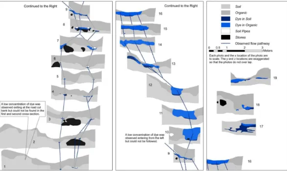
20
All excavated and analyzed cross-sections shown in Fig. 3 are in the proper x location with the y and z location exaggerated so that the flow pathways between the cross-sections could be delineated (dashed line). The pathways are not shown in cases where the distance was too large between the cross sections, or we were unable to
HESSD
5, 1043–1065, 2008 Excavation of a lateral preferential flow network A. E. Anderson et al. Title Page Abstract Introduction Conclusions References Tables Figures ◭ ◮ ◭ ◮ Back CloseFull Screen / Esc
Printer-friendly Version
Interactive Discussion
follow the feature during excavation. The first cross-section starts in the lower left corner of the first panel of Fig. 3 and then the cross-sections continue on the panels to the right. The location of each cross section can be seen in Fig. 1. The excavations revealed flow through soil pipes, zones of highly conductive soils, porous organic soils, and through the soil matrix. The soils had many live and dead roots in the upper 30–
5
50 cm, but the roots often extended down to the till layer. The till layer starts at each cross section below the defined soil or organic layer. The specific flow processes in the three dominant soil types found at this site are described in more detail below.
3.1 Clay and organic rich soils in the topographical hollow
The first soil type was shallow (less than 1 m) with a clay-rich mineral horizon (Bg)
10
and a generous Ah horizon of well decomposed organic material. In the experimen-tal hillslope, these soils were located in the topographical hollow (centre portion of cross-sections 1–9, Fig. 1), and contained a hydraulically connected set of preferen-tial features, consisting of soil pipes and areas of fine gravel (particle size 2–5 mm). The dye solution moved almost exclusively through the preferential features,
interact-15
ing only minimally with the surrounding soils. Most of the material on the bottom of the soil pipes (and filling the preferential features in cross-section 4 and cross-sections 10– 13) consisted of fine gravel, similar to sediment found in nearby small streams. This topographical hollow had the fastest velocities (calculated with Eq. 1), which were one and two orders of magnitude higher than those at the other cross-sections (Table 1).
20
The velocity in sections with pipes (1–3 and 5–9) is underestimated. We assumed that the soil pipes were completely filled with water during the experiment, while there is evidence to suggest that the pipes were only partially filled; this was clearly seen in many larger pipes where only the lower half of the inside pipe wall was stained.
HESSD
5, 1043–1065, 2008 Excavation of a lateral preferential flow network A. E. Anderson et al. Title Page Abstract Introduction Conclusions References Tables Figures ◭ ◮ ◭ ◮ Back CloseFull Screen / Esc
Printer-friendly Version
Interactive Discussion
3.2 Poorly decomposed organic soils
The second type of soil had a deep (30–50 cm), fibrous, and poorly decomposed or-ganic horizon, which contained many tree and herbaceous vegetation roots. This type of soil was found in cross-sections 10–16. Cross-sections 10–13 had vertical bands of dye within a relatively homogenous organic soil horizon. We assumed that this was due
5
to flow connecting the upper cross-section 14 to the preferential pathway located below the organic horizon in cross-sections 10–13. On the other hand, in cross-sections 14– 16 the dye solution was distributed horizontally, indicating that the flow of water used the organic soils preferentially due to their higher hydraulic conductivity than that of the mineral soil. This area of hillslope had relatively flat topography as indicated by the
10
local slopes (Table 1) with no large preferential flow features. 3.3 Brown mineral soils on the hillslopes
The final soil type observed during the excavations was brown mineral soil (Bf, 0.3– 1.5 m), often with a poorly decomposed dry organic horizon and a small (less than 5 cm) Ae horizon. These soils were found on the smaller hillslopes on the left of
cross-15
sections 1–2 and 17–19. These cross-sections corresponded with the smallest con-tributing areas (Table 1). The stained area in cross-section 17 showed flow through the organic layer and through layers of coarser mineral soil that were below the organic layer. Cross-section 18 had flow through organic soil and a Bf horizon. Within the hori-zon of lower conductivity, a 6-cm diameter soil pipe was discovered in the lower centre
20
of section 18 (Fig. 3). In section 19 the soil in the centre of the cross-section was very shallow because a windthrown tree had removed a large part of the mineral soil. The flow through this cross-section followed the subsurface topography and was confined to the organic and mineral soils above the till.
When cross-section 18 was excavated, the soil pipe was severed and dye solution
25
poured out under pressure. This soil pipe was circular in cross-section, suggesting that it was initially formed by a tree root. The bottom and sides of this pipe were lined with
HESSD
5, 1043–1065, 2008 Excavation of a lateral preferential flow network A. E. Anderson et al. Title Page Abstract Introduction Conclusions References Tables Figures ◭ ◮ ◭ ◮ Back CloseFull Screen / Esc
Printer-friendly Version
Interactive Discussion
gravely sediment of approximately 2 mm mean diameter (evidence of past erosion), and the pipe was completely filled with fine organic material. Dye solution was also around a dead root in the right-hand portion of the cross-section 18 (right upper stained area in cross-section 18). However, unlike the other pipe low in the profile, the staining was limited to the lower half of the root, which suggested that only part of the void
5
around the root was contributing to lateral flow. 3.4 Transport of soil and organic material
We speculate that fine clay and organic material were leached and transported to the hollows where they accumulated. Evidence of buried organic material within this brown mineral soil type suggested that there was preferential transport of water and fine
ma-10
terial to depth within the soil which accumulated in areas with preferential features (old and new). The lateral and vertical redistribution of fine organic material was also ev-ident in cross-sections 1, 2, 17, and 18. At the road cut-bank, a low concentration of dye solution drained from the soil face (left side of the cross-section 1 and 2 in Fig. 3). Cross-sections 1 and 2 had buried dark soil that could have been preferential features
15
filled with accumulated organic material. Although no dye solution was found within the soil, a weak dye solution was observed exiting the soil at the road cut-bank. These dark soils were connected to the same preferential flow features that showed strong response during natural events and the steady state experiments. Cross-section 17 had similar redistribution of organic material into the mineral soil.
20
4 Discussion
4.1 Modification of preferential features
As speculated by Uchida (2004) and the first null hypotheses of in this paper, there appears to be a link between the contributing area and the distribution of preferen-tial features. It is recognized that subsurface erosion contributes to stream sediment
HESSD
5, 1043–1065, 2008 Excavation of a lateral preferential flow network A. E. Anderson et al. Title Page Abstract Introduction Conclusions References Tables Figures ◭ ◮ ◭ ◮ Back CloseFull Screen / Esc
Printer-friendly Version
Interactive Discussion
(Onda, 1994; Terajima et al., 1997). This subsurface erosion is thought to be impor-tant for the modification and maintenance of preferential flow features (Uchida, 2004). This experiment showed the presence of highly developed preferential flow features corresponding to the largest contributing areas (greater than 1100 m2). These areas also had the largest percentage of hillslope outflow during rainfall events and for steady
5
state experiments. Small contributing areas (less than 400 m2) and relatively flat local topography (less than 15%) coincided with areas with few preferential flow pathways. This suggests that a soil with a small contributing area might not receive flow rates large enough to modify and maintain large preferential flow features.
The headwater catchments in these areas often have hillslopes directly connected
10
to streams. This connection between the stream and hillslope will allow the subsurface transport of sediments directly into the streams. Without an “exit” for the sediments, such as a road cut or stream bank, there will likely be an accumulation of sediment, as found in most of our excavated cross-sections. This means that the processes that maintain the preferential flow network also have the ability to fill in some features,
re-15
sulting in lower capacity and flow rate. As features in the preferential network are filled in, water will be forced into other preferential features, causing the network to change over time. This subsurface erosion and deposition could affect the soil development and help contribute to the varying soil types found in this watershed. The soils with small contributing areas contribute fine material to soils with larger contributing areas.
20
The soil cross-sections excavated during this experiment were classified into groups in the results section, which correspond to areas receiving large amounts of water, sed-iments, and organic material (cross-sections 1–13) and areas losing sediments and organics (cross-sections 14–19). Preferential transport of fine material was evident within cross-sections as well. For example, there was evidence of erosion and
deposi-25
tion in a preferential flow feature in cross-section 18. There was fine gravely material on the bottom of the feature, indicating that it was connected to an outlet that allowed erosion of finer sediments, leaving the gravely material behind. However, the pipe was filled with fine organic material suggesting that at some point in time the outlet ceased
HESSD
5, 1043–1065, 2008 Excavation of a lateral preferential flow network A. E. Anderson et al. Title Page Abstract Introduction Conclusions References Tables Figures ◭ ◮ ◭ ◮ Back CloseFull Screen / Esc
Printer-friendly Version
Interactive Discussion
to function and the feature began accumulating fine organic material. 4.2 Conceptual models of runoff
The general conceptual model of lateral preferential flow networks relies on a rising water table. As the water table rises, there is an increase in the connections in the preferential flow network, causing faster subsurface velocities and increasing the area
5
of hillslope contributing to runoff (Tsuboyama et al., 1994; Sidle et al., 2000; Uchida et al., 2005; Tromp-van Meerveld and McDonnell, 2006b). These excavations support this conceptual model. It appears that the preferential flow features were connected by matrix flow through mineral and organic soils. In some areas, this saturated flow was perched above soil with low hydraulic conductivity and spread out horizontally in
10
the overlying layers of more conductive soils. In other areas the flow had vertical com-ponents because the water was flowing downward to areas with higher conductivities. These observations showed that a connection may be established by a water table rising within a small localized area.
The subsurface flow in this hillslope is highly dynamic and depends on the
precipi-15
tation characteristics. Trenched hillslopes from around the world have identified differ-ences in subsurface flow characteristics based on the subsurface topography and the saturated zone connections of the hillslope and the trench (e.g. Tani, 1997; Hutchinson and Moore, 2000; Freer et al., 2002; Tromp-van Meerveld and McDonnell, 2006a). The excavations presented here show that trenches with large contributing areas collect
20
flow from preferential flow networks that are efficient at transferring water, due in part to a high degree of hydraulic connectivity. The soils in these areas could transport water one order of magnitude faster than other soils. The dye staining also revealed that there is often little interaction between water in the preferential flow feature and the surrounding soil matrix unless there was a constriction in the preferential flow network.
25
This is important for understanding the transport and dilution of solutes and pollutants. Solutes deposited in soils with larger contributing areas (hence a well established pref-erential flow network) will have quicker travel times and minimal interaction with the
HESSD
5, 1043–1065, 2008 Excavation of a lateral preferential flow network A. E. Anderson et al. Title Page Abstract Introduction Conclusions References Tables Figures ◭ ◮ ◭ ◮ Back CloseFull Screen / Esc
Printer-friendly Version
Interactive Discussion
water in the soil matrix, compared to solutes deposited in soils with smaller contribut-ing areas, which will travel further at slower speeds and will have more interaction with water in the soil matrix (pre-event water). This may result in more dilution and retar-dation of the solute in soils with small contributing areas relative to those with large contributing areas.
5
4.3 Landslide hazard
Landslide activity and debris flows are common at Russell Creek and surrounding ar-eas (Fannin and Wise, 2001; Nistor and Church, 2005). Arar-eas with similar topography, climate, and soil types as this watershed are also prone to landslides. Preferential features are sometimes found near landslide initiation points (Fannin and Jaakkola,
10
1999; Uchida, 2004). The water table depth and the proximity to preferential features influences the pore water pressure in these types of hillslopes. Preferential features can rapidly drain the soil water, reducing the water table and the pore water pressure (Montgomery and Dietrich, 1994 and 1995; Sidle, 1986; Fannin et al., 2000). However, when preferential features reach their capacity, are in-filled by subsurface deposition, or
15
are damaged, preferential flow could increase the landslide hazard by increasing pore water pressure on the surrounding soils (Uchida et al., 2001). The preferential features found in cross-section 18 exemplify this phenomenon. The soil pipe in the lower centre part of the cross-section (Fig. 3) had water that poured out under pressure when the cross-section was excavated. Even though this pipe was completely filled with organic
20
material, it extended up slope and held a volume of dyed water that produced a pres-sure head even 4 days after the steady state experiment was initiated. For the water to enter the feature, it had to displace water that was already in the pipe before dye solution was added to the input trench. Presumably, the dyed solution entered the pipe when the pore pressure was higher and water was displaced out of the feature down
25
slope of cross-section 18. During subsurface flow conditions, this increase in pore water pressure could increase the landslide initiation hazard. On the other hand, the subsurface flow that stained the lower half of the dead root in the right side of
cross-HESSD
5, 1043–1065, 2008 Excavation of a lateral preferential flow network A. E. Anderson et al. Title Page Abstract Introduction Conclusions References Tables Figures ◭ ◮ ◭ ◮ Back CloseFull Screen / Esc
Printer-friendly Version
Interactive Discussion
section 18 (Fig. 3) had completely drained and the only evidence of flow was dye on the root and surrounding soils. This means that this feature was hydraulically connected to lower slope sections and could drain even under low pore water pressures. At the flow rate used for the experiment, this feature would likely decrease the landslide initiation hazard because it would reduce the water table of the local area.
5
Soils with large contributing areas are often the initiation site of landslides (Uchida, 2004), which can be attributed to accumulation of subsurface water. However, it could also in part be due to the linkage between large contributing areas and highly de-veloped and hydraulically connected preferential features. If the preferential features observed in the hollow were blocked or their capacity was reached, there is a high
10
probability that pore water pressure would increase in the surrounding soils. If there were no other preferential features transmitting the water, the likely outcomes would be 1) discharge of water to surface runoff, or 2) if the condition are right, the initiation of a slope failure. The relationship between the contributing area, subsurface storm water volume, and the modification and maintenance of preferential features could be
15
used to enhance the prediction of areas with high landslide initiation hazard (e.g. Wu and Sidle, 1995). Nevertheless, we need more larger-scale excavation experiments to better develop the relationship between topographic units and preferential flow features in steep forested hillslopes.
5 Conclusions
20
We stained a 30 m section of hillslope with a food dye under steady state conditions and then excavated the hillslope to determine the lateral preferential flow features, the connections between the features, and velocities through each cross-section. At this site, the material that connected the preferential flow features was important for controlling the hillslope velocity, and the dye patterns suggested that saturated flow
25
through permeable soil provided connection between the individual preferential fea-tures. Observations of erosion and deposition of fine soil and organic material within
HESSD
5, 1043–1065, 2008 Excavation of a lateral preferential flow network A. E. Anderson et al. Title Page Abstract Introduction Conclusions References Tables Figures ◭ ◮ ◭ ◮ Back CloseFull Screen / Esc
Printer-friendly Version
Interactive Discussion
the preferential features suggested that preferential flow influenced the redistribution of the fine soil and organic material within the hillslope. Some preferential features were only partially filled with water, and others were under pressure. We tested the hypothesis that the contributing area was linked to the preferential flow network. The excavations revealed that the largest and most connected features were in the soils
5
with the largest contributing area derived from the surface topography. The large fea-tures (up to 30 cm in diameter and meters in length) transport water and solutes while interacting minimally with the surrounding soil matrix. These findings have implications for subsurface flow generation, soil development, solute transport, and slope stability and could be used to develop better predictions of lateral preferential subsurface flow.
10
Acknowledgements. We would like to acknowledge M. Hrachowitz, G. Jost, J. McDonnell, and
P. Szeftel for assisting with the excavation. The efforts of anonymous reviewers. The British Columbia Forest Investment Account Forest Science Program and the Natural Sciences and Engineering Research Council of Canada provided funding for this project.
References
15
Bouma, J., Jongerius, A., Boersma, O., Jager, A., and Schoonderbeek, D.: Function of Different Types of Macropores During Saturated Flow through 4 Swelling Soil Horizons, Soil Sci. Soc. Am. J., 41, 5, 945–950, 1977.
Fannin, R. J. and Jaakkola, J.: Hydrological response of hillslope soils above a debris-slide headscarp, Can. Geotech. J., 36, 6, 1111–1122, 1999.
20
Fannin, R. J., Jaakkola, J., Wilkinson, J. M. T., and Hetherington, E. D.: Hydrologic response of soils to precipitation at Carnation Creek, British Columbia, Canada, Water Resour. Res., 36, 6, 1481–1494, 2000.
Fannin, R. J. and Wise, M. P.: An empirical-statistical model for debris flow travel distance, Can. Geotech. J., 38, 5, 982–994, 2001.
25
Freer, J., McDonnell, J. J., Beven, K., Peters, N. E., Burns, D. A., Hooper, R. P., Aulenbach, B., and Kendall, C.: The role of bedrock topography on subsurface storm flow, Water Resour. Res., 38, 12, doi:101029/2001WR000872, 2002.
HESSD
5, 1043–1065, 2008 Excavation of a lateral preferential flow network A. E. Anderson et al. Title Page Abstract Introduction Conclusions References Tables Figures ◭ ◮ ◭ ◮ Back CloseFull Screen / Esc
Printer-friendly Version
Interactive Discussion
Flury, M. and Fluhler, H.: Tracer Characteristics of Brilliant Blue Fcf, Soil Sci. Soc. Am. J., 59, 22–27, 1995.
German-Heins, J. and Flury, M.: Sorption of Brilliant Blue FCF in soils as affected by pH and ionic strength, Geoderma, 97, 1–2, 87–101, 2000.
Ghodrati, M. and Jury, W. A.: A Field-Study Using Dyes to Characterize Preferential Flow of
5
Water, Soil Sci. Soc. Am. J., 54, 6, 1558–1563, 1990.
Holden, J., Burt, T. P., and Vilas, M.: Application of ground-penetrating radar to the identification of subsurface piping in blanket peat, Earth Surf. Proc. Land., 27, 3, 235–249, 2002.
Hutchinson, D. G. and Moore, R. D.: Throughflow variability on a forested hillslope underlain by compacted glacial till, Hydrol. Process., 14, 10, 1751–1766, 2000.
10
Kitahara, H.: Characteristics of pipe flow in forested slopes, IAHS Pub., 212, 235–242, 1993. McDonnell, J. J.: A Rationale for Old Water Discharge through Macropores in a Steep, Humid
Catchment, Water Resour. Res., 26, 11, 2821–2832, 1990.
Montgomery, D. R. and Dietrich, W. E.: A physically based model for the topographic control on shallow landsliding, Water Resour. Res., 30, 4, 1153–1171, 1994.
15
Montgomery, D. R., and Dietrich, W. E.: Hydrologic processes in a low-gradient source area, Water Resour. Res., 31, 1–10, 1995.
Mosley, M. P.: Streamflow Generation in a Forested Watershed, New-Zealand, Water Resour. Res., 15, 4, 795–806, 1979.
Nistor, C. J. and Church, M.: Suspended sediment transport regime in a debris-flow gully on
20
Vancouver Island, British Columbia, Hydrol. Process., 19, 4, 861–885, 2005.
Noguchi, S., Tsuboyama, Y., Sidle, R. C., and Hosoda, I.: Morphological characteristics of macropores and the distribution of preferential flow pathways in a forested slope segment, Soil Sci. Soc. Am. J., 63, 5, 1413–1423, 1999.
Onda, Y.: Seepage Erosion and Its Implication to the Formation of Amphitheater Valley Heads
25
– a Case-Study at Obara, Japan. Earth Surf. Proc. Land., 19, 7, 627–640, 1994.
Peters, D. L., Buttle, J. M., Taylor, C. H., and Lazerte, B. D.: Runoff Production in a Forested, Shallow Soil, Canadian Shield Basin, Water Resour. Res., 31, 5, 1291–1304, 1995.
Pierson T. C.: Soil pipes and slope stability, Q. J. Eng. Geol., 16, 1–11, 1983.
Roberge, J. and Plamondon, A. P.: Snowmelt runoff pathways in a boreal forest hillslope, the
30
role of pipe throughflow, J. Hydrol., 95, 39–54, 1987.
Sherlock, M. D. and McDonnell, J. J.: A new tool for hillslope hydrologists: spatially distributed groundwater level soilwater content measured using electromagnetic induction, Hydrol.
Pro-HESSD
5, 1043–1065, 2008 Excavation of a lateral preferential flow network A. E. Anderson et al. Title Page Abstract Introduction Conclusions References Tables Figures ◭ ◮ ◭ ◮ Back CloseFull Screen / Esc
Printer-friendly Version
Interactive Discussion
cess., 17, 10, 1965–1977, 2003.
Sidle, R. C.: Groundwater accretion in unstable hillslopes of coastal Alaska, IAHS Publ. 156, 335–343, 1986.
Sidle, R. C., Noguchi, S., Tsuboyama, Y., and Laursen, K.: A conceptual model of preferential flow systems in forested hillslopes: evidence of self-organization, Hydrol. Process., 15, 10,
5
1675–1692, 2001.
Sidle, R. C., Tsuboyama, Y., Noguchi, S., Hosoda, I., Fujidea, M., and Shimizu, T.: Seasonal Hydrologic Response at Various Spatial Scales in a Small Forested Catchment, Hitachi-Ohta, Japan, J. Hydrol., 168, 1–4, 227–250, 1995.
Sidle, R. C., Tsuboyama, Y., Noguchi, S., Hosoda, I., Fujidea, M., and Shimizu, T.:
Storm-10
flow generation in steep forested headwaters: a linked hydrogeomorphic paradigm, Hydrol. Process., 14, 3, 369–385, 2000.
Tani, M.: Runoff generation processes estimated from hydrological observations on a steep forested hillslope with a thin soil layer, J. Hydrol., 200, 1–4, 84–109, 1997
Terajima, T., Sakamoto, T., Nakai, Y., and Kitamura, K.: Suspended sediment discharge in
15
subsurface flow from the head hollow of a small forested watershed, northern Japan, Earth Surf. Proc. Land., 22, 11, 987–1000, 1997.
Terajima, T., Sakamoto, T., and Shirai, T.: Morphology, structure and flow phases in soil pipes developing in forested hillslopes underlain by a Quaternary sand-gravel formation, Hokkaido, northern main island in Japan, Hydrol. Process., 14, 4, 713–726, 2000.
20
Tromp-van Meerveld, H. J. and McDonnell, J. J: Threshold relations in subsurface stormflow: 1. A 147-storm analysis of the Panola hillslope, Water Resour. Res., 42, 2, 2006a.
Tromp-van Meerveld, H. J. and McDonnell, J. J.: Threshold relations in subsurface stormflow: 2. The fill and spill hypothesis, Water Resour. Res., 42, 2, 2006b.
Tsuboyama, Y., Sidle, R. C., Noguchi, S., and Hosoda, I.: Flow and Solute Transport through
25
the Soil Matrix and Macropores of a Hillslope Segment, Water Resour. Res., 30, 4, 879–890, 1994.
Tsukamoto, Y. and Ohta, T.: Runoff Process on a Steep Forested Slope, J. Hydrol., 102, 1–4, 165–178, 1988.
Uchida, T.: Clarifying the role of pipe flow on shallow landslide initiation, Hydrol. Process., 18,
30
2, 375–378, 2004.
Uchida, T., Kosugi, K., and Mizuyama, T.: Runoff characteristics of pipeflow and effects of pipeflow on rainfall-runoff phenomena in a mountainous watershed, J. Hydrol., 222, 1–4,
HESSD
5, 1043–1065, 2008 Excavation of a lateral preferential flow network A. E. Anderson et al. Title Page Abstract Introduction Conclusions References Tables Figures ◭ ◮ ◭ ◮ Back CloseFull Screen / Esc
Printer-friendly Version
Interactive Discussion
18–36, 1999.
Uchida, T., Kosugi, K., and Mizuyama, T.: Effects of pipeflow on hydrological process and its relation to landslide: a review of pipeflow studies in forested headwater catchments, Hydrol. Process., 15, 11, 2151–2174, 2001.
Uchida, T., Meerveld, I. T., and McDonnell, J. J.: The role of lateral pipe flow in hillslope runoff
5
response: an intercomparison of non-linear hillslope response, J. Hydrol., 311, 1–4, 117– 133, 2005.
Weiler, M. and Fluhler, H.: Inferring flow types from dye patterns in macroporous soils, Geo-derma, 120, 1–2, 137–153, 2004.
Wu, W. and Sidle R. C.: A distributed slope stability model for steep forested basins, Water
10
HESSD
5, 1043–1065, 2008 Excavation of a lateral preferential flow network A. E. Anderson et al. Title Page Abstract Introduction Conclusions References Tables Figures ◭ ◮ ◭ ◮ Back CloseFull Screen / Esc
Printer-friendly Version
Interactive Discussion
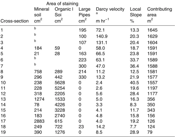
Table 1. The area of stained soil, pipe cross-sectional area, velocity of the flow through each
cross-section.
Area of staining
Mineral Organic l Large Darcy velocity Local Contributing soil Soi Pipes a Slope area Cross-section cm2 cm2 cm2 m hr−1 % m2 1 b 195 72.1 13.3 1645 2 b 100 140.9 20.3 1629 3 b 107 131.1 20.4 1604 4 184 59 0 58.0 18.7 1591 5 21 28 163 66.5 23.8 1591 6 b 223 63.1 33.7 1589 7 b 300 47.0 36.4 1588 8 758 289 214 11.2 12.5 1581 9 296 442 330 13.2 21.9 1577 10 238 5628 0 2.4 40.5 1557 11 228 5254 0 2.6 19.6 1197 12 318 2205 0 5.6 28.4 1177 13 1274 1533 0 5.0 16.3 356 14 78 4226 0 3.3 8.3 350 15 214 3228 0 4.1 11.7 343 16 183 2740 0 4.8 15.8 156 17 2883 615 0 4.0 19.2 126 18 249 722 23 14.2 7.7 124 19 390 1276 0 8.5 28.9 79 a
Darcy velocity for the cross-sections with stained soil was as;V =Q/As, whereAsis the stained area plus the area of the pipes, where applicable.
b
Staining around pipes was not presumed to be from transmit water flow, but from water transferred from the soil pipes.
HESSD
5, 1043–1065, 2008 Excavation of a lateral preferential flow network A. E. Anderson et al. Title Page Abstract Introduction Conclusions References Tables Figures ◭ ◮ ◭ ◮ Back CloseFull Screen / Esc
Printer-friendly Version
Interactive Discussion
Fig. 1. Contour map of the experimental hillslope showing the location of the dye injection and
the photographed cross-sections. This map was developed using the 256 total station survey points for the excavated section and another 262 points for the rest of the hillslope.
HESSD
5, 1043–1065, 2008 Excavation of a lateral preferential flow network A. E. Anderson et al. Title Page Abstract Introduction Conclusions References Tables Figures ◭ ◮ ◭ ◮ Back CloseFull Screen / Esc
Printer-friendly Version
Interactive Discussion
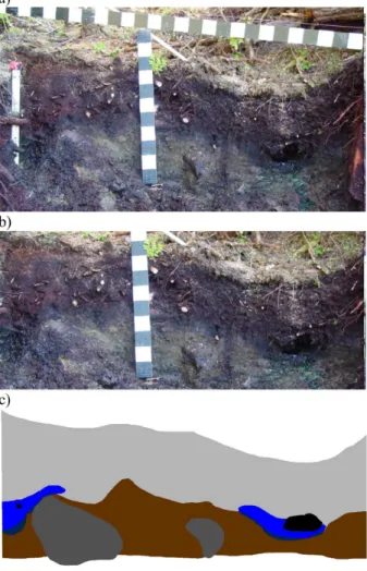
Fig. 2. Cross-section 7, examples of (a) the original photo, (b) the rectified colour corrected
HESSD
5, 1043–1065, 2008 Excavation of a lateral preferential flow network A. E. Anderson et al. Title Page Abstract Introduction Conclusions References Tables Figures ◭ ◮ ◭ ◮ Back CloseFull Screen / Esc
Printer-friendly Version
Interactive Discussion
Fig. 3. Cross-sections showing the location of the stained soil, the soil pipes, and the observed
flow paths between the cross-sections. The photos and the x locations are to scale but the y and z locations have been exaggerated so that the photos do not overlap.