HAL Id: insu-02270108
https://hal-insu.archives-ouvertes.fr/insu-02270108
Submitted on 23 Aug 2019
HAL is a multi-disciplinary open access
archive for the deposit and dissemination of
sci-entific research documents, whether they are
pub-lished or not. The documents may come from
teaching and research institutions in France or
abroad, or from public or private research centers.
L’archive ouverte pluridisciplinaire HAL, est
destinée au dépôt et à la diffusion de documents
scientifiques de niveau recherche, publiés ou non,
émanant des établissements d’enseignement et de
recherche français ou étrangers, des laboratoires
publics ou privés.
SCADE 6 A Model Based Solution For Safety Critical
Software Development
François Dormoy
To cite this version:
François Dormoy. SCADE 6 A Model Based Solution For Safety Critical Software Development.
Embedded Real Time Software and Systems (ERTS2008), Jan 2008, toulouse, France. �insu-02270108�
SCADE 6 A Model Based Solution For Safety Critical Software
Development
François Xavier Dormoy
11: Esterel Technologies, Park Avenue, 9 rue Michel Labrousse, 31100 Toulouse, France
Abstract: SCADE Version 6 is both a language and
a Safety Critical Development Environment that brings a new Unified Modeling Style that provides a seamless and safe flow from system to software engineering. This flow relies on strong foundations where safety is considered at each step that allows engineers to focus on key issues whilst removing a significant part of the burden of the development process.
SCADE6 is a model based tool that has been designed to cope with engineers needs together with safety constraints expressed in several standards such as D0178-B, EN50128 or IEC 61508.
This paper presents SCADE version 6 and points out the key factors we have addressed during the language definition, modelling environment and code generation development in order to cope with a safety critical development flow.
Keywords: Model-driven-design, formal-methods,
SCADE, safety-critical, Synchronous Languages.
1. Introduction
1.1 Safety Critical Software challenges
Avionic, railway and automotive systems have become very complex to develop without the assistance of a design environment tool that eases the engineering process.
Complex applications such as cockpit display
systems, guidance systems, engine controls,
autopilots or interlocking systems require a seamless
and safe transition from abstraction to
implementation.
Model-Based Design delivers those benefits that include:
• Addressing the complexities inherent in
control systems designs,
• Starting software design before physical
systems are available,
• Verifying the system prior to the
implementation, so that errors in the
specification of requirements can be
detected and eliminated earlier in the development cycle,
• Creating a structure for software reuse that
allows a reliable and cost effective upgrade path for established designs.
1.2 Overview of SCADE
SCADE (Safety Critical Application Development Environment) is both a language and a toolset that
was specifically developed to describe and
implement safety critical applications. SCADE is the
result of a collaboration between Verimag,
Aérospatiale (now Airbus), Merlin Gerin (now Schneider Electric) and Verilog.
It relies on the theory of synchronous languages for real-time applications and, in particular, on the Lustre and Esterel languages as described in [1],[9] and [2],[7].
The synchronous approach is a cycle-based execution model of SCADE. This is a direct computer implementation of the ubiquitous sampling-actuating model of control engineering. It consists of performing a continuous loop of the form illustrated in Figure 1 below. In this loop, there is a strict alternation between environment actions and application actions. Once the input sensors are read, the cyclic function starts computing the cycle outputs. During that time, the cyclic function is blind to environment changes. When the outputs are ready, or at a given time determined by a clock, the output values are fed back to the environment, and the program waits for the start of the next cycle.
Figure 1: The cycle-based execution model of SCADE Suite
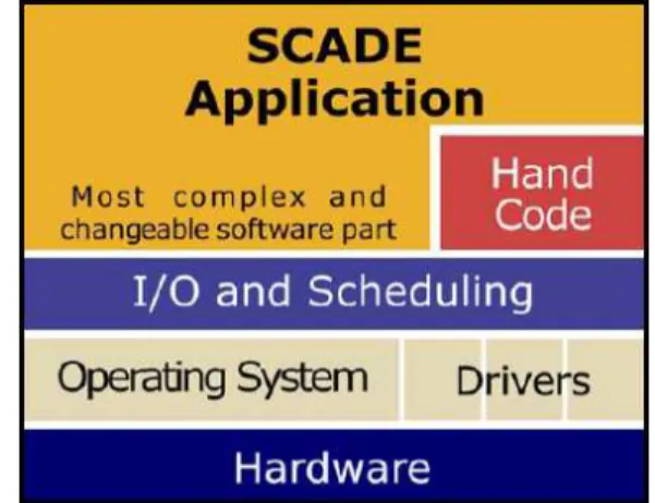
SCADE addresses the applicative part of hard real-time software, as illustrated in Figure 2.
This is usually the most complex and changeable aspect of software, containing complex decision
logic, filters, and control laws. It typically represents 60% to 80% of the software embedded in an airborne computer.
Figure 2: SCADE addresses the applicative part of software
SCADE represents a bridge between Control Engineering and Software Engineering because it provides a common, rigorous graphical and textual language for both communities that reflect control engineering constructs:
• Its data flow structure fits the block diagram approach.
• Its time operators fit the z operator of control engineering. For instance, z-1, the operator of control engineering (meaning a unit delay), has an equivalent operator called “pre” in SCADE.
SCADE is now used for critical control software in aircraft, helicopters, nuclear power plants and railway switching systems.
SCADE modelling capabilities cover designing, verifying and optimising complex algorithms, control intensive applications, and graphic interfaces. Furthermore, the SCADE automatic Code Generator has been qualified to produce a portion of the evidence mandated by certification authorities, supporting a safety-critical process in a cost effective manner.
2. SCADE 6: Unified Modelling Style
SCADE Version 6 is a new version of the SCADE language that keeps the foundation (formal and synchronous execution, strong typing, explicit initialization of data flows, explicit management of time, simple expression of concurrency) and extends the modelling capabilities towards several directions:
• Data flow extensions that improve the
control part (reset, activate, merge)
• Control features expressed in terms of
state-machines
• Safe loop features implemented using higher
order iterators
• Other modelling features that improve the
connection to the environment (Sensor) and ease the reusability with a better
encapsulation of data (Package) and polymorphism
2.1 Data flow extension toward control Work performed [5] started with defining an extension of the data flow part with several
constructs that will be the support for state machine extension.
restart is a higher-order operator that allows to
retrieve the initial state. This construct is very useful in dataflow model in order to implement reset feature without modelling this with inputs, wires and if/switch constructs.
The syntax of a restart instantiation is: (restart N every c)(e).
Example: 1 PRE 0 C c = 0 -> (1 + pre c); Node : Count
Figure 3: Count Node
1
Count r
C
C = (restart count every r )(); Node Resettable_Count
Figure 4: Resettable_Count Node This primitive affects flow initializations in the instantiated node by making them returning their first argument as if it were the first cycle. Example in figure 6,7 and the behaviour shown in figure 8 illustrates this purpose.
Examples:
PRE
0
sum e
sum = 0 -> e + pre sum; Node Sigma
Figure 6: Sigma Node
0 10 PRE s 1 Sigma 1 Count
s = (restart sigma every (0 -> pre s >= max ))(count ()); Node Sample
Figure 7: Sample Node
Figure 8: Sample node behaviour
The second extension is about introducing a merge operator that builds a flow on top of complementary clocked flows. merge takes, as first argument, a clock identifier h used to select one of its other inputs.
This operator evaluates first the value of its clock expression. Depending on this value, the
corresponding expression is defined at the current cycle and its value is the result of its evaluation as shown in figure 9.
Figure 9: merge semantics
Examples:
Figure 10 represents an Integrator node that generates 1 outputs: s, the integator output.
PRE 0 s e s = e + (0 -> pre s); Node integr
Figure 10: Integr Node
Figure 11 represents a two_instance node that generates 2 outputs: s, the integator output and t a merge output. 0 WHEN h PRE e WHEN h 1 integr t h e 2 integr s Node two_instances s = integr (e);
t = merge (h; integr (e when h); (0 -> pre t) when not h); v 3
v 2 v 1
Figure 11: two_instance Node Figure 12 illustrates the behaviour of the merge.
Figure 12: two_instance node behavior The third main extension is about improving the imperative features in Data flow. In SCADE previous versions, when and mainly condact were the only way to control computation. In SCADE version 6, the control feature is extended toward 2 directions:
Control activation of an operator: activate on
operator is a higher order constructs providing 3 usages:
• activate <N> every <clock_expr>: N is activated
when clock expression is true. The result is clocked in sync with <clock_expr>. This is
• activate <N> every <expr1> default <expr2>: This construct is a variant of the previous one without memorization of the result of N when <expr1> is false. N is activated when <expr1> is true.
• activate <N> every <expr1> initial default
<expr2>: This construct is equivalent to condact in the previous SCADE versions. N is activated when expr1 is true. When expr1 is false, the result is initialized with <expr2> and after one computation of N, the result sustains the last result of N.
Example of activate initial default:
0 e h 2 integr t s 1 integr e s = integr (e);
t = ( activate integr every h initial default 0) (e); Node two_instances_2
Figure 13: node two_instance_2
Figure 14: two_instance_2 node behaviour This node behaves as the two_instance node using merge.
Example of activate default:
0 e h 3 integr t s 1 integr e Node two_instances_3 s = integr (e);
t = ( activate integr every h default 0) (e); Figure 15: node two_instance_3
Figure 16: two_instance_3 node behaviour
Control activation of a set of equations: activate
on a set of equations is now possible in SCADE 6 in order to make conditional computations. This is possible through Boolean conditions (activate if) or through enumerated conditions (activate when match). These constructs are called clocked_blocks. • activate [<id>] if <expr> then <equation_set1>
else <equation_set2>: if <expr> is true <equation_set1> is computed, this set of equations could contain other clocked block.
• activate [<id>] when <expr> match {{<pattern> :
<equation_set>}}+ Example of activate if:
node two_instances_4(e:int ; h:bool) returns (s:int ; t:int last = 0) let
s = integr (e); activate if h
then t = integr (e); else t = last ’t; returns t;
tel
Note : last ‘t is the notation to get the last value of t in the scope of its declaration. pre is the notation to get the previous value in the scope of the block.
Figure 17: two_instance_4 node behaviour
2.1 State-machine
When the application is data-flow dominated (e.g., regulation systems), it will naturally go for block diagram formalisms as it is provided in SCADE for years. On the contrary, when the application is more control dominated (e.g., cockpit displays), imperative or state-machine based formalisms as the ones provided by StateCharts [10], the Sync-Chart [7] or Esterel [2], [8] will certainly be better choices. Nonetheless, real systems rarely fall into one category and are often a mix of both styles. The extension provided in SCADE 6 allows to mix both styles in a conservative way [5],[6] meaning that all new state-machine features are translated (compiled) to basic clocked data flow. In that way the
state-machines bring useful syntactical facilities but do not break the data-flow principles.
Let us explain the main principle through an example. We choose the same example as in [11] that illustrates how a data can be computed in several ways according to modes.
<UD> B 1 last 'x x A last 'x 1 x 1 x >= 5 1 x <= -5 In textual :
Figure 18: Node UpDown
Figure 19: UpDown node behaviour The initial state is A, in this state x is computed
according to x = last’x + 1, last’x is the value
of x in the previous cycle in the complete state-machine. When x >= 5 then the cycle after (weak
transition) state B is activated. x = last’x-1 is
then computed until x<=-5.
State transitions:
SCADE offers three different kinds of state transitions: strong, weak and synchronisation transition. The two first ones correspond to common ways to fire a transition in control models. The last one allows synchronizing parallel state-machines. In SCADE, a State Machine has one and only one active state per cycle.
This property preserves the unicity of the definition of a flow during a cycle.
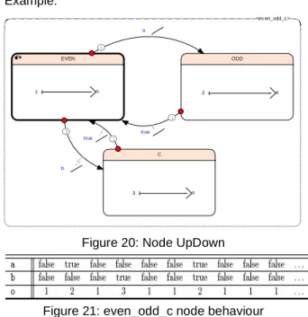
With strong preemption transition, when the transition is fired, the target state becomes active within the cycle.
Example: <ev en_odd_c> C 3 o ODD 2 o EVEN 1 o 1 a 2 b 1 true 1 true
Figure 20: Node UpDown
Figure 21: even_odd_c node behaviour With weak transition, when the transition is fired, the target state becomes active the cycle after but the actions on transition are activated within the cycle. Example:
<ev en_times_delay ed>
ODD i -2 o EVEN 1 i o 1 c 1 c
node even_times_delayed (c: bool; i : int ) returns (o: int ) let
automaton initial state EVEN let
o = i + 1 ; tel
until if c restart ODD ; state ODD
let o = -2 * i ; tel
until if c restart EVEN ; returns o;
tel
Figure 22: Node even_time_delayed
A state can be flagged as final by using the keyword final before the keyword state. Any state can be final (even the initial one) and a State Machine is not limited to only one final state.
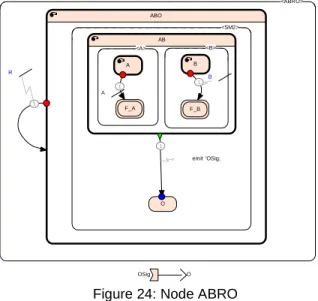
Given a state S containing several sub-State Machines running in parallel, if at the next cycle all these sub-State Machines are in a state marked as final, then a synchronization transition can be fired from state S. The target state becomes active the cycle after but the actions on the transition are activated within the cycle (as for weak transitions). Example:
The example illustrated bellow (Figure 24) shows a state-machine that detects two events (A and B) independently of the way it occurs, A before B or B before A or A and B simultaneously. When both events are detected, F_A and F_B are active then the synchronisation transition is fired and OSig signal is emitted. R is a preemption transition that resets the state-machine.
OSig O <ABRO> ABO <SM2> O AB <B> F_B B <A> F_A A 1 A 1 B 1 R 1 emit 'OSig;
Figure 24: Node ABRO The state-machine is translated by the code
generator to clocked blocks as shown in the example below. <SM1> ST1 -2 i o ST0 1 i o 1 c0 1 c1 In textual :
node N (c0 : bool; c1 : bool; i : int) returns (o : int) let automaton SM1 initial state ST0 unless if c0 restart ST1; o = i + 1; state ST1 o = -2 * i; until if c1 restart ST0 ; returns o; tel Figure 20: Node N
The flow state_sel carries the notion of selected state, state_act, the notion of activated state, and state_next, the notion of the next cycle’s selected state. The equation defining state_act uses state_sel and the strong transition part of the automaton’s states. The equation defining state_next uses state_act and the body and the weak part of the automaton. These variables belong to an
enumerated type that represents the states of the automaton (one enumerator per state). Since only one transition must be fired during a cycle, the knowledge of already fired strong transition in the selected state must be used before firing a weak transition in the active one. A type enumerating all possible transitions is used therefore.
type
A_states = {ST0 , ST1 };
A_trans = {no_trans,ST0_strong_1, ST1_weak_1 };
Node N_Bis2(c0 : bool; c1 : bool; i : int) returns (o : int) var state_sel : A_states; state_act : A_states; state_next : A_states; fired_strong : A_trans; let
state_sel=ST0 -> pre state_next; activate A1 when state_sel match |ST0 :
let
state_act =if c0 then ST1 else ST0; fired_strong =if c0 then S0_strong
else no_trans ; tel |ST1 : let state_act = ST1; fired_strong = no_trans ; tel
returns state_act , fired_strong; activate A2 when state_act match
|ST0 : let o = i + 1; state_next = ST0; tel |ST1 : let o = -2 * i; activate if fired_strong <> no_trans then state_next = ST1;
else state_next=if c1 then
ST0 else ST1 ;
returns ..; tel
returns o, state_next ; tel
2.3 Safe loop (iterators)
Repeating a computation for large array data or computing vectors or matrices is very common in embedded systems. The challenge for a modeling language addressing safety critical systems is to provide safe loop constructs. The principle in SCADE version 6 is to provide several predefined iterators scheme. We present in this paper the main ones.
Iterators are again higher order operators with the following general syntactic form:
X = (iterator Node <<dimension >>) ( arguments ) ;
Map:
Given a node N, that requires k arguments, and k arrays of size d. Let suppose now that the expected result is a new array of size d built out of the application of node N to the successive elements of these arrays, as follows:
X = [ N(x[0] ,... ,z [0]) , N(x[1] ,... ,z [1]) , ... , N(x[d -1] ,... ,z[d -1]) ] ;
This expanded form can be summarized using the map iterator applied on node N:
X = (map N <<d > >)(x ,... ,z) ;
Example:
Pointwise sum of two arrays can be expressed in the following way: b a c Node Sum_scalar c = a + b
Figure 21: Node Sum_Scalar
v u t 1 Sum_scalar map<<3>> Node sum_array
Figure 21: Node Sum_array
Fold:
The fold operator also allows applying a node successively to array arguments. But contrary to map operator, it does not build an array of the same size as its arguments: it provides an element belonging to the basic type of the arrays (called
accumulator) which is initialized in the called
parameter then passed from one array element to the next one. The result is the accumulator provided by the N applyed to the last element.
Example Sum of the elements of an array:
s 0 1 Sum_scalar fold<<3>> a t Node Array_sum
Figure 22: Node Array_sum
s = Sum_scalar ( Sum_scalar ( sum_scalar (0, t[0]) , t[1]) , t [2]) ;
Other iterators exist such as mapfold which is a combination of map and fold, others iterators allow to get access to the index of the computation (mapi,
foldi, …).
2.3 Other modelling features
Assume and guarantee:
Design-by-contract is a clean and safe software engineering principle. A contract is a specification of the condition of use and the expectations of a function (or a node).
This contract is made of a pair of observers. • one corresponding to condition of use: assume, • one corresponding to ensured properties:
guarantee.
Assume and guarantee do not impact the semantic of the model, they are part of the model for proof purpose.
Sensor:
A sensor defines a global flow that can be read anywhere by the model, and is a model input. A sensor is semantically very close to a constant but with the ability to be updated between each cycle. A sensor should remain stable during all the cycle computation.
Package:
The package (or module or namespace) mechanism is a software engineering feature provided by many program languages. It makes the design and the usage of libraries easier.
A package definition is a block of declarations starting with the keyword package and the name of the package and ended with the keyword end followed by a semicolon.
package Integer type T = int ;
const ZERO : T = 0 ;
function plus (x,y: T) returns (z: T) z = x+y;
end;
Polymorphism:
SCADE provides a way to define generic nodes, also called polymorphic nodes. Genericity is expressed by using type variables written as quoted ident.
node sample_generic (a,b: ’T) returns (c: ’T)
var
flag : bool ; let
flag = true -> not (pre flag ) ; c = if flag then a else b ; tel
The quoted ident ’T represents a type variable: a, b and c can be of any type. The only constraint they have to fulfil is that they belong to the same type. If more than one type variable is required in a node profile, one has to use a different quoted ident.
3. Safety apply to SCADE 6 itself
3.1 Framework safety principles
SCADE 6 is a model based framework made of several tool addressing Safety critical systems. In this section, we address some of the key points that contribute to the safety of the complete tool chain. The question we want to answer here is: “what are the characteristics that can make a tool chain suitable in safety-critical context?”
First, the language (or the formalism) is one major point. In the first part of the paper we have presented it and let’s recall the main characteristics:
• formal, deterministic and documented
• graphical and textual (with a mapping between
both)
• simple and powerful (the tradeoff is very difficult
to tune)
• precise and concise
Derived from these principles:
• Only one assignment per variable shall be
possible per cycle
• Only one state shall be active per state-machine
and cycle
• Only one transition shall be fired per
state-machine and cycle
• Semantic errors shall be detected at compile
time in order to prevent most of the runtime errors (except overflow, underflow, div0):
o Type check
o Clock check
o Initialization check
o Causality check
Then, once the language is formally defined, the main goal of the approach is to generate code out of the description (model) of the system.
Currently the most appropriate approach is the certification approach according to standards like DO-178B and IEC 61508 and EN 50128.
In the future, the proof of the correctness of the code generator should be very suitable and for the time being, this approach is only experimented in academics [13].
The code generator takes as input files containing the description of the model according to language concrete syntax.
The graphical editor has to generate these files (storage file) with a clear separation between the graphical data and the semantical data. The graphical data should only contain drawing data (positions, size, etc) and shall not impact the semantics.
The editing feature is generally out of the scope of the certification but the tool should be intuitive and should avoid source of errors. The constraint to address is to be able during edition to save the model in a correct syntactic form (wrt to language) in order to be able to load it afterward to continue the modeling work. This has a huge impact on all editing principles
3.2 Standards
It’s important that the same standard requested by the application is fulfilled by the tool. For that reason, the Code generator has been developed according to standards such as DO178-B, EN 50128, IEC 61508. Several other tools like MTC (Model Test Coverage), CVK (Compiler verification Kit) and the Reporter has been qualified according to DO178-B as verification tool.
3.3 Design and developments
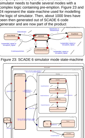
SCADE 6 has been used to model and code some complex part of the SCADE 6 simulator. The simulator needs to handle several modes with a complex logic containing pre-emption. Figure 23 and 24 represent the state-machine used for modelling the logic of simulator. Then, about 1000 lines have been then generated out of SCADE 6 code generator and are now part of the product
<ModeStateMachine> StepMode DirectMode ContinuousMode IdleMode 1 ContinuousAction 2 DirectAction 3 StepAction or ResetAction 1 'suspended_signal or 'exception_signal 1 'suspended_signal or 'exception_signal 1 'suspended_signal or 'exception_signal
Figure 23: SCADE 6 simulator mode state-machine <SimulatorStateMachine> Exit SimuLoaded <StateMac hine2> Exc eption Running <PauseMgt> Pause Run <StateMachineRunning> End InputSet OuputReady InSubN ode Suspended 1 StepAction or ContinuousAction or DirectAction 1 StepDoneInjection 1 OutputGetInjec tion 1 InputSetInjection 2 AbortTickInjection 1 PauseAction 1 ExceptionInjection 2
( 'end_of _tick and 'pause_asked) or ( 'end_of _tick and Break Injection)
3
( 'end_of _tick and 'c ontinuous_signal) or ( 'end_of _tick and 'direct_signal)
4 'end_of _tick 1 R esetAction 2 ExitAction
Figure 24: SCADE 6 simulator state-machine
4. Conclusion
SCADE 6 is a major step that addresses safety critical systems. It has been designed to address such systems, reducing the gap between the system engineers and the control engineers. It has been designed with the same standard as embedded systems (DO-178B, EN 50128, IEC 61508) and sometimes with the same tools (SCADE 6 itself).
6. Acknowledgement
My sincere thanks to following people:
• Jean Louis Colaço and Bruno Pagano:
Authors of SCADE 6 language
• G. Berry, N. Halbwachs P. Caspi : SCADE 6
Synchronous foundations with Lustre and Esterel
• SCADE 6 team: The people that make it
real!
7. References
[1] N. Halbwachs: “Synchronous Programming of
Reactive Systems“, Kluwer, 1993.
[2] G. Berry: “The Foundations of Esterel“, In Proofs,
Languages, Essays in Honour of Robin Milner”, MIT Press, 2000.
[3] Jean-Louis Colaço and Marc Pouzet: . Clocks as
First Class Abstract Types. In Third International Conference on Embedded Software (EMSOFT’03), Philadelphia, Pennsylvania, USA, october 2003.
[4] Jean-Louis Colaço, Alain Girault, Grégoire Hamon,
and Marc Pouzet: Towards a Higher-order Synchronous Data-flow Language. In ACM Fourth International Conference on Embedded Software (EMSOFT’04), Pisa, Italy, september 2004.
[5] Jean-Louis Colaço, Bruno Pagano, and Marc
Pouzet: A Conservative Extension of Synchronous Data-flow with State Machines . In ACM International Conference on Embedded Software (EMSOFT'05), Jersey city, New Jersey, USA, September 2005.
[6] Jean-Louis Colaço, Grégoire Hamon, and Marc
Pouzet: Mixing Signals and Modes in Synchronous
Data-flow Systems . In ACM International
Conference on Embedded Software (EMSOFT'06), Seoul, South Korea, October 2006.
[7] Charles André: Representation and Analysis of
Reactive Behaviors: A Synchronous Approach. In CESA, Lille, july 1996. IEEE-SMC. Available at: www-mips.unice.fr/»andre/synccharts.html.
[8] G. Berry and G. Gonthier: The Esterel synchronous
programming language, design, semantics,
implementation. Science of Computer
Programming, 19(2):87–152, 1992
[9] N. Halbwachs, P. Caspi, P. Raymond, and D.
Pilaud: The synchronous dataflow programming language lustre. Proceedings of the IEEE, 79(9):1305–1320, September 1991.
[10] D. Harel: StateCharts: a Visual Approach to
Complex Systems. Science of Computer
Programming, 8-3:231–275, 1987.
[11] F. Maraninchi and Y. Rémond: Mode-automata:
About modes and states for reactive systems. In European Symposium On Programming, Lisbon (Portugal), March 1998. Springer verlag.
[12] F. Maraninchi and Y. Rémond: Mode-automata: a
new domain-specific construct for the development of safe critical systems. Science of Computer Programming,(46):219–254, 2003.
[13] Marc Pouzet: Towards the Development of a
Certified Compiler for Lustre. Workshop
SYNCHRON Bamberg, nov. 27th, 2007.
8. Glossary
SCADE: Safety Critical Application Development Environment