Determining the Optimal Set of Solutions for Storage and Conveyance of Tools in a Highly Variable Manufacturing Environment
By Erin E. Golden B.S. Chemical Engineering The Pennsylvania State University, 2010
Submitted to the MIT Sloan School of Management and the Department of Mechanical Engineering in Partial Fulfillment of the Requirements for the Degrees of
Master of Business Administration and
Master of Science in Mechanical Engineering
In conjunction with the Leaders for Global Operations Program at the Massachusetts Institute of Technology
June 2017
2017 Erin E. Golden. All Rights Reserved.
The author hereby grants to MIT permission to reproduce and to distribute publicly paper and electronic copies of this thesis document in whole or in part in any medium now known or hereafter created.
Signature of Author
Signature redacted
Department of Mechanical Engineering, MIb Sloan School of Management May 12, 2017 Certified by Certified by Certified by Accepted by Accepted by MASSACHUSElTS INSTITUTE MASSACHUSETTS INSTITUTE OF TECHNOLOGY
JUN 20 2017
Signature redacted_
Annalisa Wfigel, Thesis Supervisor Senior Lecturer, Adjunct Faculty, MIT AffiliateSignature- redacted
DanIiik1ey, Thesis Supervisor Senior Research Scientist Emeritus, MIT Leaders for GlobpI Operations
Signature redacted
1
Thomas'Roeer, Thesis Reader Executive Director, Leaders for Gl9bal Operations, MITSignature redacted
Maura Herioidbirecto' of MIT Sloan MBA ProgramMIT Sloan School of Mantgement
Signature redacted
Rohan Abeyaratne, Chairman, Committee ontraduate Students(0 Department of Mechanical Engineering
uJI
Determining the Optimal Set of Solutions for Storage and Conveyance of Tools in a Highly Variable Manufacturing Environment
By Erin E. Golden
Submitted to the MIT Sloan School of Management and the Department of Mechanical Engineering on May 12, 2017 in partial fulfillment of the requirements for the degrees of Master of Business
Administration and Master of Science in Mechanical Engineering
ABSTRACT
In November 2013, Boeing launched a derivative of the 777 airplane, known as the 777X, which will be the largest and most efficient twin-engine
jet
in the world when it enters service in 2020. In parallel withnew airplane development, Boeing is transforming its existing 777 production system through an initiative known as FPS, or Future Production System (FPS), in order to create a more safe, flexible and productive manufacturing environment that accommodates the 777 and 777X. This will require upgrades to be made to the existing 777 manufacturing process.
FPS requirements include the need for a system to better support the mechanic by implementing "final stage tool kitting." My project scope was to plan, design, and implement a tool kitting process for the Service Ready Wing (SRW) area of 777 Manufacturing. The first part of this thesis evaluates the prescribed solution of tool kitting and attempts to evaluate its potential cost and benefit to 777 SRW Manufacturing. The thesis then systematically approaches the problems for which tool kitting is trying to solve, rather than the solution itself. The result is a set of solutions discussed in Chapter 7 that focuses on reducing tool inventory, floor space, and non-value added time of the mechanic.
This thesis is intended to serve as a model for all areas of 777 and 777X Manufacturing as teams continue to work towards understanding how to improve tool management. By providing a systematic approach to evaluating the current-state tool usage in a specific manufacturing area, and focusing proposed solutions on actions that solve a defined problem set agreed to by key stakeholders, this work will help guide other
groups towards creating successful, sustainable tool conveyance solutions.
Thesis Supervisor: Annalisa Weigel
Title: Senior Lecturer, Adjunct Faculty, MIT Affiliate Thesis Supervisor: Daniel Whitney
Title: Senior Research Scientist Emeritus, MIT Leaders for Global Operations Thesis Reader: Thomas Roemer
ACKNOWLEDGEMENTS
I would like to jointly thank MIT's LGO program and the Boeing Company for their longstanding partnership that has made my internship experience possible and allowed me to connect with so many knowledgeable and helpful LGO alumni throughout the duration of my time in Everett. A huge thanks to my amazing supervisor, Sally Smith, for teaching by example and showing me what it means to be a motivating, positive, and incredibly effective leader. Thanks to my thesis advisors, Dan Whitney and
Annalisa Weigel, for their guidance throughout my internship and their on-site visit which helped me to develop the ultimate direction of this project.
Thanks to the 777 Wing Body Join Manufacturing team for allowing me to regularly take over their weekly Employee Initiative Meetings, and to the Tool Services organization for their continued efforts in trying to better service the mechanic. Thanks to my small but mighty "Kitting Team," without whom I would probably still be sitting somewhere foam-cutting toolkits. Your painstaking data collection efforts
have helped create a cultural shift in the perception of kitting, and I feel confident that you will achieve continued success with our tool kitting strategy going forward!
I would also like to thank my friends for all their support throughout this process: my fellow LGO students who have always made themselves available to share ideas and provide feedback, and my "non-LGO" friends I can always count on to provide the best distractions when I need a break from school.
Lastly and most importantly, I thank my family: my parents, who could not be more supportive of my decision to embark on this incredible 2-year journey, and my younger sister, Lindsey, who has always been my biggest supporter and best friend. I am truly one lucky girl to have you all in my life.
Table of Contents
A BSTR A C T...3 A C K N O W LED G EM ENTS ... 5 1. IN TR O D U CTIO N ... 10 1.1 THESIS O VERVIEW ... 10 1.2 PURPOSE OF PROJECT ... 111.3 O RIGINAL PROBLEM STATEM ENT ... .12
1.4 PROJECT H YPOTHESIS...13
1.5 PROJECT G OALS ... 13
1.6 PROJECT A PPROACH- O RIGINAL AND REVISED ... 14
2 O PER A TIO N S A T TH E BO EIN G C O M PA N Y ... 15
2.1 BACKGROUND OF COM PANY ... 15
2.2 SITE BACKGROUN D ... 15
2.3 BOEING 777...16
2.4 BOEING 777 SERVICE READY W ING ... 17
2.5 M ARKET COM PETITIVENESS: W HY TRANSFORMATION IS NEEDED... 18
3 LITER A TU R E R EV IE W ... 18
3.1 LITERATURE ON TOOL. CONVEYANCE AND K ITTING ... 19
3.2 LITERATURE ON LEAN...20
3.3 LITERATURE ON SYST EMA TIC PROBLEM SOLVING ... 22
4 M ETH O D O LO G Y ... 24
4.1 CURRENT STATE ANALYSIS: BENCHMARKING IN FAUB AND 787 ... 24
4.2 C URRENT STATE A NALYSIS: 777 SRW ... 27
4.3 TOOL DATA COLLECTION AND A NALYSIS... 30
4.4 W ORKING THE PRESCRIBED SOLUTION ... 34
4.4.1 Long Term Vision Cart W orkshop Results ... 37
4.4.2 IP Toolkit Validation and Testing... 39
5 O V ER V IEW O F C U LTU R E ... 41
5.1 O RGANIZATIONAL DISCONNECT... 42
5.2 THREE LENS ANALYSIS OF THE 777 SRW PROGRAM KITTING INITIATIVE...42
5.2.1 Strategic D esign Lens ... 42
5 .2 .2 C u ltu r a l L e n s ... 4 3 5 .2 .3 P o litic a l L e n s ... 4 4 6 WORKING BACKWARDS: FROM SOLUTION TO PROBLEM ... 45
6.1 CHANGING THE D IRECTIVE ... 45
6.2 SURVEY RESULT FEEDBACK ... 46
6.3 ESTABLISHING THE PROBLEM ... 47
6.4 RE-DEFINING THE SOLUTIONS...48
6.4.1 Inventory Reduction ... 48
6.4.2 Floor Space Reduction...49
7 PILOT TESTING OF THE SELECTED SOLUTIONS...50
7.1 M ETHODOLOGY/A PPROACH TO TESTING ... 50
7.].1 Inventory Reduction...51
7.1.2 Floor Space Reduction...53
7.1.3 N VA T Reduction...57
7.2 D ISCUSSION OF RESULTS ... 59
7.3 A PPLICATION TO OTHER AREAS OF 777 PRODUCTION LINE ... 59
8 RECOMMENDATIONS AND CONCLUSIONS...60
9 R EFER EN C ES...63
FIGURES
F IG U RE 1: 777 T O O LKIT E X A M PLE ... 12
FIGURE 2: B O EIN G PRODUCT L IN EUP ... 16
Figure 3: O utline of SR W W orking Space ... 17
FIGURE 4: % DIFFERENCE IN SCHEDULED V ACTUAL TIME (MIN) TO COMPLETE A JOB IN FAUB...25
FIGURE 5: % DIFFERENCE IN SCHEDULED V ACTUAL TIME (MIN) TO COMPLETE A JOB IN SRW...26
FIGURE 6: OVERLAPPING CIRCLES REPRESENT TOOLS USED ON MULTIPLE JOBS ... 31
FIGURE 7: KITTING COST/BENEFIT ANALYSIS USING $0 SALARY DELTA AND 6% NVAT ... 35
FIGURE 8: MODEL OF SUPPORT PERSONNEL NEEDED TO SUPPORT TOOL KIT DELIVERY AND RETRIEVAL .. 36
FIGURE 9: FIN AL STAGE C A RT FOR 787...37
FIGURE 10: FINAL STAGE CART FOR FA U B ... 38
F IG U RE 11: EX PAN D A BLE S ID ES ... 39
FIGURE 12: RAISED EDGING TO ENSURE ITEMS DO NOT ROLL OFF SURFACE...39
FIGURE 13: SURVEY RESPONSES ON PROBLEMS ASSOCIATED WITH TOOLS ... 47
FIGURE 14: AREA 2 PLUMBING BAG PAIL E TS. EACI I 15" x 20" x 6" ... 52
FIGURE 15: REVISED AREA 2 SINGLE PALLET PLUMBING BAG ... 53
FIGURE 16: H1 YPOTHESIS TESTING RESULTS... 61
TABLES TABLE 1: ORIGINAL SOLUTION STATEMENT FOR TOOL KITTING PROJECT ... 12
TABLE 2: TOOL-SPECIFlC TASKS AND THEIR % OF TOTAL JOB COMPLETION TIME...28
TABLE 3: ALL NVAT RELATED TASKS AND THEIR % OF TOTAL JOB COMPLETION TIME...29
TABLE 4: TOOL D ATA FOR SR W A REAS ... 30
TABLE 5: SRW KIT AND CART ANALYSIS SUMMARY ... 33
TABLE 6: RESULTS OF K IT TESTING FOR 5 JOBS...40
TABLE 7: SUMMARY OF COMMODITY BAG UPDATES ... 53
TABLE 8: TOOL BAG SIZE REDUCTION *ASSUMING BAGS ARE STACKED IN GROUPS OF FIVE ... 54
TABLE 9: C C 127 TOOLBOXES 13Y SHIFT ... 54
1. INTRODUCTION
The introduction of any new technology into a longstanding manufacturing system brings about new challenges, both technical and cultural. In most organizations experiencing such changes, scenarios relating to technical concerns will be tested ahead of time (at Boeing, this is a new practice known as Production Integration Testing, or PIT). Cultural concerns however, often go untested and as a result become the toughest to overcome in implementation. This thesis examines a problem, inefficient methods for providing mechanics with the tools they need, for which the original prescribed solution did not fully consider cultural and cost-related concerns that would result in almost assured failure to both implement and sustain meaningful improvements. It then details a re-evaluation of the problem, focusing on implementation efforts that directly address cultural concerns. The solutions discussed in Chapter 7 that are ultimately implemented are done so with complete buy-in of key stakeholders in this process change, including the Manufacturing, Tool Services, and Materials Management organizations. The result is a smaller step-change in the journey towards fully kitted tools than original project goals may have stated, but assures greater success in terms of sustainable systematic improvements than would have been possible had cultural considerations been neglected.
1.1 THESIS OVERVIEW
In order to fully appreciate the learnings and insights gained over the course of my internship, this thesis covers two distinct phases of work: the first half dealing with working on the original project as it was presented to me, and the second half focusing on re-evaluating the project itself and defining my own problem to solve. The time and effort that went into gaining management support to not implement the original solution with which I was tasked is something that helped grow my leadership and problem-solving abilities immensely, and is worth highlighting as guidance for future "solution-based" projects. The remainder of this chapter is focused on providing an overview of the project itself. To best
understand why decisions were made to change the direction of the project, the reader needs a more detailed understanding of both the company as whole and the day-to-day work that occurs in the 777 SRW area to set the stage: this occurs in Chapter 2. Chapter 3 discusses literature on tool kitting, the
concept of "Lean" more broadly, and the systematic problem solving method that was used to provide solutions to tool conveyance issues facing 777 Service Ready Wing. Once the reader understands the background information provided in Chapters 1-3 a discussion of how the first half of the project was managed, which occurred during the first three months of this internship, takes place in Chapter 4. Once the reader is more familiar with the initial efforts in managing this project, the cultural component of working in 777 SRW Manufacturing is discussed in Chapter 5, in order to develop a complete
understanding of why this project shifted direction mid-way. Chapter 6 is dedicated to this change and the re-defined problem statement that ultimately shaped the solutions highlighted in Chapter 7. Chapter 8 concludes this work by providing the reader with a full summary of the problem-solving approach that was used in this project, which should be used as a framework for future projects led by 777 and 777X Manufacturing teams.
1.2
PURPOSE OF PROJECTThe purpose of this project was to successfully complete one piecc of the overall "Future Droction
System (FPS)," for the 777 as part of a larger Boeing Commercial Aircraft (BCA) production initiative. This system design update aims to implement automated and / or robotic fixtures that move multi-model (777 and 777X) airplane assemblies throughout the manufacturing line to support single piece flow and improved flow times, while still supporting the massive assembly components and their design and build requirements. Along with automation, a system to better support the mechanics, including "final stage kitting," increased service level support from factory personnel, improved quality plans and significantly reduced flow times will be implemented. My piece of this project scope was to plan, design, and
implement a tool kitting process for the Service Ready Wing (SRW) area of 777 Manufacturing. The available build floor space for these areas will be reduced as a part of this production initiative, which is something I needed to consider in my process development.
The mission of tool kitting, as it was defined to me, was providing a shadowbox of necessary tools to the mechanic each time a new IP was performed. An IP is an Installation Plan, or a job that a mechanic performs to build, test or inspect the airplane, and each IP takes approximately two hours to complete.
See Figure 1 below for visual examples of a shadowbox tool kit.
FIGURE 1: 777 TOOLKIT EXAMPLE
Note that, for the purpose of this thesis, "tools" will refer to hand tools only, and not large-scale equipment that is also sometimes referred to by the same term.
1.3 ORIGINAL PROBLEM STATEMENT
The original problem statement that I had based my initial analysis and testing efforts on was taken from a Kitting Vision Future Production System document that was presented to me during my first week onsite. The excerpt that dealt specifically with tool kitting is shown below:
Initial Kitting Vision Long-Term Kitting Vision
Delivered in 2 hour (by-IP kits) at bus stop Delivered in 2 hour (by-IP kits) at bus stop Hand Delivered to bus stop every 8 hours Delivered to bus stop every 2 hours
Tools 2 flow days of kits stored at TIC 8 hours of kits stored at TIC
TABLE 1: ORIGINAL SOLUTION STATEMENT FOR TOOL KITTING PROJECT
My task was to design a hand tool storage and conveyance method that would achieve the "Initial Kitting Vision" of delivering 2 hour by-IP toolkits to a location on the floor near the mechanics' point of use, referred to as the "bus stop." Initially, this vision showed delivery to the bus stop during every shift, or every eight-hour period. Two flow days' worth of kits and carts (on which kits were delivered) were to
be stored in the Tool Integration Center, or TIC. The TIC was part of the initial proposed design that was ultimately not used in my final storage and utilization design. The Future State Vision, shown in the second column of TABLE 1, was something that I was asked to plan for, but did not necessarily need to fully implement during the course of my project, due to timing of overall FPS implementation. A detailed discussion of the current state of 777 SRW Manufacturing and how tools were being managed will be provided in Chapter 2.
1.4 PROJECT HYPOTHESIS
My initial hypothesis was that by gathering and analyzing data on tool usage by job, or IP, performed, I would be able to implement a successful "by-IP" kitting process for the 777 Service Ready Wing (SRW) area based off of the Initial Kitting Vision requirements that are shown in Table 1. This would include completing data analysis, workshop sessions with mechanics to gain customer buy-in, and solution testing. After data analysis and workshops had been completed, my hypothesis shifted to a more general statement: by gathering and analyzing data on tool usage by job performed, l would be able to determine the optimal tool kitting/conveyance system for the 777 SRW area of 777 production. This would include definitions of each tool kit, a schedule on how and when they would be delivered to and from the floor, and a detailed understanding of the additional resource requirements that would be needed to achieve this schedule.
1.5 PROJECT GOALS
For the first half of this project, my primary goal was simply to implement a final stage tool kitting process for the SRW area. Key metrics of success were based on the toolkits that I planned to develop:
e Quality - are toolkits being delivered with first-pass quality? How often does the mechanic need to step away from the plane to procure a tool that was not provided to him/her?
- Kit Revisions - are kits being re-defined and iterated in a timely manner (within 24 hours of request)?
- Productivity -Is set-up time for mechanics reduced as a result of kitting?
After better understanding the additional inventory and resources that would be needed to achieve this goal, as described in Chapter 4.2.2, my goals shifted from those stated above to reducing the mechanic's Non-Value Added Time (NVAT) spent setting-up, breaking down, and searching for tools.
One goal that remained constant throughout the duration of this project was to develop a systematic approach for evaluating an existing tool conveyance process in a given area to determine the best possible set of improvement options. Up until this point, other areas in 777 Manufacturing had been developing tool kits without a thorough evaluation of existing state needs. My intention, through company
presentations and this thesis, was to provide a blueprint which could be used to standardize the process by which improvements to existing tool conveyance methods were made.
1.6
PROJECT APPROACH- ORIGINAL AND REVISEDMy original approach, as detailed in Chapter 4, was to first observe and document how tools were being stored and utilized in the current state process in 777 SRW, and which organizations were involved in and responsible for this. Next, I performed the same analysis in the areas that had already implemented tool kitting: the 787 Program and the FAUB (Fuselage Automated Upright Build) area of the 777 Program, to incorporate best practices from those initiatives into my own work. During my internship I worked with five industrial engineers who interviewed all SRW mechanics to determine which tools were needed to perform each job. I analyzed the data that they collected in order to understand the best type of kitting model for this area. Once I had decided on my ultimate approach, a good portion of my remaining time was spent gaining management buy-in on allowing 777 SRW to implement a tool conveyance design that was different from models previously laid out in other manufacturing areas. I relied on a detailed
2
OPERATIONS AT THE BOEING COMPANY2.1
BACKGROUND OF COMPANYBoeing celebrated its 1 0 0"' year of operation in 2016, and with this came media reflections on the
company's achievements over the last century. In an article written in The Atlantic, Boeing's biggest challenges over the next century are said to be minimizing environmental impact of their products while continuing to drive faster, more economical solutions ("A Century in the Sky"). This drive to reduce manufacturing costs can be felt throughout the organization, which is one that prides itself in
implementation of Lean Processes, a concept further discussed in Chapter 3.
2.2 SITE BACKGROUND
The Boeing Factory located in Everett outside of Seattle, WA, is the largest building in the world by volume, covering 472 million cubic feet. In January 1967, the facility opened and was originally
designed to build the 747 only. Today, it is the location where the Boeing 747, 767, 777, and 787 are all assembled. More than 30,000 people work at this facility, which has its own fire department, security team, and fitness center. The challenges in beginning a new position at a facility of this size were similar to what one may experience when moving to a new city: securing a parking space can be extremely challenging; navigating the entire complex is a difficult task that often results in being late to meetings; the sheer number of people in the building makes one feel a bit overwhelmed at first, but in time it all becomes more familiar. The size of the facility also played a role in the culture within 777
Manufacturing. In "Emerging from Turbulence: Boeing and Stories of the American Workplace Today," authors Leon Grunberg and Sarah Moore note a recent dramatic shift in Boeing's corporate culture due to "a focus on cost-cutting and bottom-line profits, a hard line with unions, outsourcing of work, and a steely approach to layoffs and work transfers." While these changes have undoubtedly also been felt across many other American manufacturing plants, the size of the Everett facility brings more opportunity for rumors to spread quickly. As a result, messaging around any cost-cutting actions needs to be clearly directed all the way down the organizational hierarchy, as discussed in Chapter 3.1.
2.3
BOEING
777
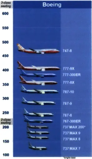
The Boeing 777 is a family of wide-body twin-engine jet airliners, commonly referred to as the "Triple Seven." It was designed to bridge the capacity difference between the 767 and 747, as shown in Figure 1.
.0
300 250
FIGURE 2: BOEING PRODUCT LINEUP (THE BOEING COMPANY, 2014)
The first 777 entered commercial service on June 7, 1995. The advanced technologies implemented in the initial design included glass cockpit flight displays, a fiber optic avionic network, and digital fly-by-wire controls. To accommodate production of this airliner, the Everett factory size was doubled to provide space for two new assembly lines. In January 2016, Boeing announced a rate reduction from 8.3 planes/month to seven planes/month due to a lack of new orders, in part because of the next generation 777 model discussed in Chapter 2.4. This rate reduction generated feelings of low morale among mechanics, contributing to cultural concerns that are raised in Chapter 5. As a regular attendee of
mechanic shift meetings, I experienced firsthand the questions raised around job security, for which management was not able to provide definitive answers.
2.4 BOEING 777 SERVICE READY WING
The 777 Service Ready Wing manufacturing area, which was the focus area of this project, is where all the work needed to fully prepare the wings before they were attached to the fuselage of the plane is
completed. A rough outline of this area is shown below in
FIGURE 3: the red boxes denote existing toolbox area, which is about 25-40 feet away from most locations in which mechanics are working in this area.
E]
FIGURE 3: OUTLINE OF SRW WORKING SPACE
Each job, referred to as an IP (Installation Plan), takes approximately two hours to complete. The jobs completed in Service Ready Wing jobs are performed across three shifts, with approximately 78% of mechanics working on each of the first two shifts, and approximately 22% of mechanics on the third shift. A large subset of these jobs are handled by electricians, as wiring is a critical component to ensuring wing readiness. A wide variety of tools are also needed to support this work: approximately 884 unique types of hand tools are utilized by the mechanics in SRW. A more detailed discussion of how the mechanics obtained, stored, and utilized tools can be found in Chapter 4.2. A number of different organizations support the mechanics in completing their work. During my initial observations, I found that while most tools were kept on the floor in toolboxes, which were managed by the Manufacturing team, certain tools
were kept in a tool room, managed by the Tool Services support organization. In general, Manufacturing preferred ownership and management over their own materials as much as possible, by keeping tools in toolboxes on the floor versus in the tool room, which was a cultural nuance that needed to be considered as part of this project, and is discussed further in Chapter 5.
2.5
MARKET COMPETITIVENESS: WHY TRANSFORMATION IS NEEDEDIn November 2013, Boeing launched a derivative of the 777, known as the 777X, which has already sold a number of airplanes through pre-orders (approximately 300 as of August 2015). The 777X will be the largest and most efficient twin-engine jet in the world, with lower fuel consumption and lower operating costs than the competition when it enters service in 2020. In parallel with new airplane development, Boeing is transforming its existing 777 production system through the FPS initiative, as discussed in Chapter 1.1, to create a more safe, flexible and productive environment that accommodates the 777 and 777X. Both models will be manufactured on the same line in the Boeing Factory, and thus both will need to be supported by the same set of tools and equipment. This will require upgrades to be made to the existing 777 production system.
3
LITERATURE REVIEWMuch of the kitting research available to date focuses on kitting parts rather than tools. In 777 SRW Manufacturing, parts are already kitted through a process that works fairly well: parts are delivered to a specific area on the floor based on the schedule of jobs to be performed for the day, and are consumed as these jobs are performed. While schedule delays often occur in 777 Manufacturing, the fact that each part needs to be consumed at some point in the build process, and only so many parts per airplane exist, ensures that no serious part buildup on the floor occurs. A key difference between kitting parts and tools, and one that adds significant complexity to the overall tool kitting process, is inventory management: tools are not consumed by the plane as the build process evolves (just the opposite: great efforts are taken to ensure that no tools remain on the plane while it is being manufactured). This results in the need for a two-way inventory flow of tools, and not the one-way flow process through which parts are currently
managed. Additionally, parts are used exactly once in a specific assembly sequence, while multiple tools can be used for the same jobs, and the same tool can be used for different jobs. All of this adds to the complexity of managing tools.
3.1
LITERATURE ON TOOL CONVEYANCE AND KITTINGA study focused on implementation of tool kits notes that one of the first questions that needs to be asked when evaluating tool kitting is "What are the preferences of service engineers with regards to tools and tool kits?" (Vliegen, Kleingeld, & van Houtum, 2010). The survey results feedback discussed in Chapter 6.2 provides an overview of the opinions of mechanics and other Boeing employees with regards to tool kitting. This study highlights the fact that in order to fully kit tools, a greater number of tools are typically needed than are used in a current non-kitted process state. However, it also warns against considering only increased tool costs without understanding other aspects of tool kitting, because this could lead to the conclusion that tool kits should not be used at all. The need for more tools in order to implement by-Ir toolkits was certainly true
or
777/ 3ervice Ready vv g, as shown In T able 4, but one of my goals was to determine whether this increased cost was justified.Overall, different kitting strategies seem to have varying degrees of success in different manufacturing environments. The opportunity for improvement is summarized well in a study completed at Caterpillar by Carlsson and Hensvold (2007): "Kitting does not automatically bring the benefits described in this research, it provides an opportunity to bring them, but without an organizational effort kitting might just lead to the opposite. Kitting demands a great deal from an organization, especially when it comes to information. Without accurate information, accurate kits can't be done. Without accurate kits, assembly can't be done without end product quality defects. With end product quality defects you end up with
dissatisfied customers and in the long run without any business." With this in mind, a key question that I needed to address as a part of this project was whether 777 Service Ready Wing had the ability to provide the increased organizational efforts that a successful tool kitting process demanded.
Many companies consider kitting to be a "lean" practice, as it attempts to address wasted time associated with waiting for tools and unnecessary movement. In the company as a whole, Boeing places emphasis on utilizing lean manufacturing techniques, and has an entire organization dedicating to implementing these techniques on the shop floor. The theory behind lean processes is discussed in the following section.
3.2
LITERATURE ON LEANFeld (200 1) breaks down the concept of Lean Manufacturing into five parts, noting that each part is critical to the development of a world-class manufacturing environment. These five parts are described below:
* Manufacturing Flow: the aspect that addresses physical changes and design standards * Organization: the aspect focusing on roles/functions, training, and communication
e Process Control: the aspect directed at monitoring, controlling, and pursuing ways to improve the
process
* Metrics: the aspect addressing visible, results-based performance measures
- Logistics: the aspect that provides definition for operating rules and mechanisms for planning and controlling material flow
He then goes on to note that even with effective operations in each of these areas, true competitive advantage can only be gained through three underlying principles: (1) building an empowered workforce, (2) engaging all employees by steering their collective energies in the same direction, and (3) empowering this workforce with expectations and accountability to get the job done.
During my time at Boeing, I found that the company was diligent about pursuing opportunities within each of the five parts mentioned above. Entire teams were set up around these elements, and all were
involved in project improvement opportunities. A huge opportunity for improvement with these teams exists when considering the principles that contribute to an organization's competitive advantage. While
select employees demonstrated a feeling of empowerment when working on lean projects, the
organization as a whole could have used more engagement and direction, as mentioned in Chapter 5.2.2.
A key concept that is often brought up in the discussion of Lean manufacturing principles is that of "muda." According to Krajewski et al. (2007), the essence of Lean is to maximize the value added by each activity in an organization by paring unnecessary resources and delays from them. These unnecessary resources are referred to as waste, or "muda." Taichhi Ohno, the creator of the Toyota Production System, originally defined seven wastes on which to focus elimination efforts, eventually adding an eighth. These are reviewed by Corakci (2008) and briefly described below:
e Waste of - Waste of e Waste of * Waste of * Waste of * Waste of e Waste of e Waste of
Overproduction: producing items when there are no orders Waiting: waiting time by workers, materials, or customers
Unnecessary Movement: bending, stretching, walking, or looking for materials Transporting: inefficient transportation of materials
Over processing/Incorrect Processing: unneeded or inefficient processes Unnecessary Inventory: excess raw materials and finished materials Defects: producing defective parts
Untapped Human Potential: not engaging or listening to employees
The major goals of tool kitting in general are focused on reducing the wastes of waiting and unnecessary movement. Current state measurements of these wastes are exemplified in Chapter 4.1.2. For my project in particular, I also focused on reducing the waste of untapped human potential. I wanted to involve affected employees in each step of the journey towards developing a sustainable improvement to tool conveyance in 777 SRW Manufacturing, and recognized that many mechanics had valuable insight into improvement opportunities in my project area: they just hadn't been asked for this feedback in the past.
3.3
LITERATURE ON SYSTEMATIC PROBLEM SOLVINGSo, how was the solution of tool kitting determined to be the ideal state scenario for 777 Manufacturing? Was this determined through data analysis or experience and intuition? In general, people tend to be poor intuitive problem solvers. They formulate hypotheses with incomplete data- and even when this
information is available, they tend to ignore it if it does not support existing preferences (Dawes, 1982). Tyre, Eppinger, and Csizinszky (1995) examined the role of systematic problem solving versus more intuitive approaches in driving changes on the shop floor. Their results show that systematic problem solving leads to better quality and more robust solutions, without requiring additional time in comparison to using intuitive approaches.
What does a systematic problem solving approach entail? Many different approaches have been established in attempt to answer this question, each with a unique set of questions to answer as one evaluates the problem-at-hand. One of the oldest and simplest approaches to systematically solving a math problem is a set of four principles first published in 1945 by George Polya. These principles are outlined below:
1. Underst anU L11 e problem: What is ul VV I ta L UIIKHIWI%- s avaiale?
2. Devise a plan: What is the connection between the data and the unknown? Polya suggests several strategies in devising this plan, including: looking for a pattern, eliminating possibilities, and working backwards
3. Carry out the plan: Be careful to check for mistakes at each step!
4. Check the solution: Check the results and reflect on the experience: What worked/what didn't?
While these techniques may not have originally been intended for use in a manufacturing environment, I found that this problem solving approach provided a way to plan and communicate my project work in a simple, easy to follow methodology.
Building on this, Tyre, Eppinger, and Csizinszky (1995) developed a more robust, eight-step model to problem solving, intended for use specifically in manufacturing-related areas. This model is described below.
I. Problem Description: Recognize a set of symptoms as a problem.
2. Problem Documentation: Gather quantitative and/or qualitative data on the nature of the problem in order to characterize it more fully.
3. Hypothesis Generation: Consider one or more alternative explanations before settling on an agreed "cause" of the problem.
4. Hypothesis Testing: Develop experiments and collect data to test hypotheses.
5. Solution Planning: Once a diagnosis is made, collect, analyze, and select among possible solution ideas.
6. Solution Implementation: Translate the solution plan into hardware, software, and/or procedures as required. This may involve adoption of existing approaches or development of new
technology.
7. Solution Verification: Collect data to test whether the solution implemented actually solves the problem.
8. Incorporation: Incorporate the solution into the process so that the problem will not recur.
Steps 2, 4, and 7 involve data gathering and observation, steps 1, 3, and 5 involve analysis. Finally, steps 6 and 8 involve action.
While I did not gain an understanding of the history behind the tool kitting initiative at Boeing, my intuition was that the level of data gathering and analysis recommended by this model is far more than what was used when tool kitting was originally determined to be the most effective solution in tool improvement for the 777 manufacturing process. I relied on an increased focus on analysis to change the
mindset of those that were already set on tool kitting as the only feasible solution. Chapter 8 provides a summary of my project work using Tyre, Eppinger, and Csizinszky's 8 step model.
4
METHODOLOGYThis chapter describes the work I did in pursuit of the original problem statement. This comprised benchmarking other kitting operations at the Everett factory, gathering data on existing tool usage and conveyance in 777 SRW, and trying to justify the original vision of kitting. When this effort did not produce a convincing justification, I changed my approach.
4.1
CURRENT STATE ANALYSIs: BENCHMARKING INFAUB
AND787
Mechanics in the 777 program obtained their tools through a variety of methods, depending on the specific job, or IP. In my first week at Boeing, I spent a majority of my time job shadowing in FAUB, a manufacturing area which had recently simultaneously implemented a new build process and a new tool kitting process. FAUB is a system of robots that fastens 777 fuselage sections together. FAUB is in active use but is also evolving as the company learns more about operating a complex robotic system.
While observing in FAU IB I was examining their process as a model for developing SR W's tool kitting strategy. FAUB was kitting their tools by "bar," where each bar represented one shift of activity for a single mechanic. The overall plans for bars of work to complete each day are held in "bar charts," which are owned by the Industrial Engineering (JE) team. These charts provide a blueprint of work for each airplane that is manufactured across The Boeing Company. I learned quickly that in FAUB, actual jobs being performed changed very frequently and were not often worked according to the bar chart sequence. This caused huge issues in the tool kitting plan, which depended on stability in sequence to kit tools with enough lead time. During my observations, I examined a scramble before each shift to pull together what mechanics would need for the next shift, which was often based on a piece of paper that a manager would hand to a person in the Tool Integration Center (TIC), where tools were being kitted. Overall, the lesson I learned from my time shadowing in FAUB was that in order for any level of tool kitting/delivery system to work, production would need to be stable, and a schedule would need to be followed.
Because FAUB involves a new manufacturing process, whereas SRW is well-established, I was hopeful that a schedule was more closely followed in SRW. In order to better understand the level of instability present in FAUB versus SRW, I evaluated the average time scheduled to complete a job compared to the actual time it took to complete a job (clock-in to clock-out by mechanic) in FAUB compared to SRW. This comparison was taken across the first 500 jobs in performed in each respective area, and averaged over the 25 planes most recently manufactured. For reference, in an ideal state, no variability should exist and every job should be marked at 0% for an on-time completion. Results are shown below: in order to visualize the magnitude of the relative instability in each area, the same axis limits were used for each graph.
FAUB % difference
700% 600% 500% 400% 300% 200% 100% 0% -100% 1 Im* -200%SRW % difference
700% 600% 500% 400% 300% 200% 100% 0% -100% 00 0 0 0 - r-r 400 -200%FIGURE 5: % DIFFERENCE IN SCHEDULED V ACTUAL TIME (MIN) TO COMPLETE A JOB IN SRW
A comparison of FIGURE 4 and FIGURE 5 shows that jobs scheduled in FAUB take significantly longer than scheduled to complete versus those in SRW. It should be noted that while SRW is more stable, actual completion time is regularly double (+100%) the scheduled (i.e., anticipated) completion time, demonstrating that the bar chart in SRW was by no means a model to follow, but was just more stable compared to FAUB.
I had originally thought that FAUB would provide me with a model for tool kitting that I would simply need to implement in SRW. After shadowing this area, I left feeling like I had witnessed a system that added cost to the manufacturing process, without seeing any of the benefit that should have been gained from reducing a mechanic's time spent locating tools. Continuing to look for an example of success in tool kitting, I visited the 787 program, which was the only other area in the Everett facility that had also implemented tool kitting. In discussions with members of the Lean team who were associated with this project, the message I received was that their kitting process was going much more smoothly due to better pre-work instructions that they had put in place with mechanics. This included creating paper records with a list of tools by IP and having the mechanic validate that the tools for the jobs they worked were listed correctly.
However, spending an hour with the 787 TIC manager showed me that their kitting process was not running nearly as well as I had been led to believe. By ramping up headcount in support staff, they were able to better handle the increasing amount of work that came with implementing tool kitting, but at a significant cost to the program. The paper records of tools needed by IP that were used to create the initial toolkits were incorrect about 40% of the time. Root cause analyses of the incorrect data led back to a variety of reasons: mechanics were not actually working the jobs when they reviewed the list of tools for each job, and often times more tools were needed than they realized; different mechanics preferred to complete jobs using different tools; ergonomic requirements were different based on size of person; etc. The TIC Manager also expressed a concern over the number of tools that were being purchased in order to support this new kitting system. Unique tools were now needed for each IP, because each job now had its own shadowboxed toolkit. As a result, tools that were previously shared in toolboxes could not be so any longer.
Budget constraints were not something that had been discussed in my original project proposal, but after spending time in the 787 program, I had two main cost concerns: the number of support personnel that would be needed to kit and maintain tools in SRW, and the cost of purchasing new tools to support tool kitting. Before focusing on costs associated with changes, I needed to understand exactly how tools were currently being conveyed within the area where I was assigned.
4.2
CURRENT STATE ANALYSIS:777 SRW
Spending time on the manufacturing floor was the best way to understand how mechanics procured the tools that they used to complete each job. In SRW, tools were obtained one of three ways:
1. Toolboxes, which are permanently assigned to the SRW area: 69 toolboxes in total of varying sizes.
2. Tool bags, also referred to as "process kits:" used by mechanics who perform specific job types, such as plumbing and electrical. These are used on a variety of jobs and often require additional tools from the toolbox in order to fully complete an IP.
3. Tool Room tools: Mechanics travel to a tool room to check out any additional tools that might be needed to complete a job.
When watching mechanics set-up their work area for the day, I noted that it took a significant amount of time in order to get all of the materials that they needed to complete their job, which was further demonstrated in the time study data discussed below. While I was only focused on tools, opportunity certainly existed to improve the conveyance strategy for all materials, such as parts, standards (very small parts like fasteners), and cutters (drill bits) and I wanted to better understand how all of this impacted the overall time that a mechanic spent completing his or her job. Industrial Engineers regularly complete time studies on specific jobs to determine how much time is spent doing each particular task of a job. When looking at all of the time study data collected in 2015 in the SRW area (11 time studies in total), the following items were directly associated with tool-related functions:
% of Job Completion Time
PrepWork Set Up Tools 2.0%
PrepWork Get Tools 1.4%
Pr epV UIrk )reak "own Tools I.U%
PrepWork Return Tools 1.1%
Delay Search Tools 0.2%
TOTAL 6.3%
TABLE 2: TOOL-SPECIFIC TASKS AND THEIR % OF TOTAL JOB COMPLETION TIME
This total amount of time seemed very low to me, especially considering how much focus this project had received as an improvement opportunity. It seemed as though this improvement project was chosen without fully understanding what the root cause of a mechanic's non-value added time actually was. By broadening the scope to include at all "non-value added time" categories, a much bigger opportunity for improvement exists. Only examining items associated with Prep Work and Delays (not associated with lunch time or predetermined breaks) shows that 35% of a mechanic's time is spent performing non-value added tasks that would fall under the waste category of "Unnecessary Movement." A breakdown of this information is shown below.
% of Job Completion Time
Delay Inspection I %
Delay Other 2%
Delay Talking 2%
Delay Waiting 14%
PrepWork Break down 3%
PrepWork Clean up 3%
PrepWork Get 3%
PrepWork Return 1%
PrepWork Set Up 6%
TOTAL 35%
TABLE 3: ALL NVAT RELATED TASKS AND THEIR % OF TOTAL JOB COMPLETION TIME
While this was not the focus of my project, bringing this information to the attention of management in the 777 program allowed for a separate project to be approved which examined non-value added time more broadly.
As I spent more time on the manufacturing floor gaining a better understanding of the current state of 777 SRW's tool conveyance, I also had informal discussions with mechanics on their thoughts on the idea of tool kitting. Overall, most seemed to think that the theory of being given all tools they needed exactly when they needed them made sense, but it was clear that they did not think this was realistically achievable and provided me with many very valid concerns surrounding instability of the bar chart, highlighted previously in FIGURE 5, and tool preference by mechanic. Additionally, they were all quick to recount past examples of projects that had similar intentions, but had failed in implementation. The most notable of these was the Andon initiative. Andon is a lean concept, defined by Moore (2007) as a simple visual system consisting of a visible light or sign that shows the state of an operation. Its purpose is to quickly inform the appropriate people when there is a problem so they can attend to it. When lights are used, they are normally coded: Green = Okay, Yellow = Problem, Red = Breakdown. At Boeing, computers were set up around the manufacturing area so that mechanics could enter emergent needs for materials as they arose during the work day, with colored lights as described above to highlight the level
of urgency for the request. The mechanics told me that the system worked for certain material requests, but that any time a tool was requested, Tool Services did not respond in a timely manner to the request. As Thomas Watson, former CEO of IBM, once said, "The toughest thing about the power of trust is that it's very difficult to build and very easy to destroy." After a few requests for emergent tools that went unanswered in the Andon system, mechanics simply stopped trusting in and using the system. As a result, these computers sat idle around the manufacturing area; I never once saw them used during my time on the floor, and many were literally covered in dust. Attempting to create a new type of system would first require the difficult step of re-building the trust of the mechanics.
4.3
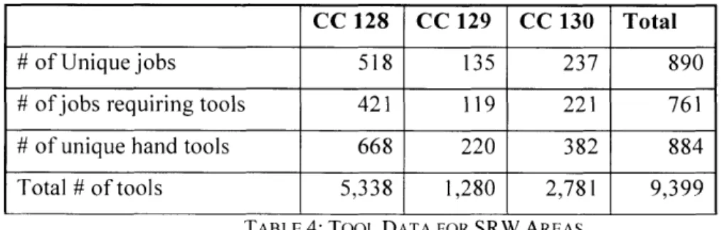
TOOL DATA COLLECTION AND ANALYSISA team of four Industrial Engineers worked across all three shifts in SRW and documented the tools that were used for each job in this area. They entered this information into a database referred to as the Kit Materials Integration system, or KMI. This database is also being used by FAUB to kit tools based on the data entered for each job. After the first-pass data entry had been completed, I was able to analyze each control code, a unique set of work within SRW to complete with an independent crew of mechanics, to understand the quantity and cost associated with the tools used in all jobs across the area. SRW contained three control codes: 128, 129, and 130. A summary of this data is shown in Table 4.
CC 128 CC 129 CC 130 Total
# of Unique jobs 518 135 237 890
# of jobs requiring tools 421 119 221 761
# of unique hand tools 668 220 382 884
Total # of tools 5,338 1,280 2,781 9,399
TABLE 4: TOOL DATA FOR SRW AREAS
The first problem that I was able to solve with this data was whether or not it made sense to create a base kit for each mechanic in SRW. A base kit is a standard kit of identical tools provided to each mechanic. This is something that was utilized in FAUB, and seemed like a potentially simple option for maintenance of toolkits. The concept of a base kit relies heavily on the level of tool commonality across the jobs for
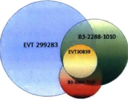
which a base kit would be used. If many jobs use similar tools, then providing each mechanic with one set of these tools, and kitting any additional tools that might be needed for specific jobs in supplemental kits, would require less tools to be purchased overall than if tools were kitted by job. However, after evaluating tool commonality across the 890 IPs in SRW, I found that base kits did not appear to be a solution that would be helpful to the mechanic or cost effective to the program. Across all 890 IPs, many tools were used commonly across less than 10 IPs, but very few tools were shared commonly across more than 40 IPs. When trying to understand how many jobs would be well served by the "ideal" basekit, the
results showed that at most, four tools could be shared across 16 IPs. FIGURE 6 provides a visual
representation of the lack of tool commonality across the IPs in SRW, showing that the highest degree of tool commonality in control code 130 is four tools that are used commonly across 16 IPs. Each circle represents a tool, and the size of the circle represents the number of times that particular tool is used in the completion of an IP. The locations where circles overlap represent where these tools are used to complete the same jobs, which is a very small area for all four circles.
83-228S-1010
EVT 299283
FIGURE 6: OVERLAPPING CIRCLES REPRESENT TOOLS USED ON MULTIPLE JOBS
Implementing base toolkits was just one idea in a series of possible kitting solutions, and in order to determine the best tool kitting option, I relied mainly on discussions with Lean personnel at Boeing in order to determine other tool kitting options for evaluation. Below are the options and descriptions that I evaluated. For each, the type of cart (or conveyance method on which the kit would be placed and used to deliver to the mechanic) is also specified.
1. IP Kits on IP Carts: Each job would have a specific toolkit associated with it that contained all tools necessary to perform that job; each job would also have a specific cart associated with it on which all other kitted materials (parts, standards, cutters) would be placed and delivered to the mechanic.
2. IP Kits on Bar Carts: Each job would have a specific toolkit associated with it that contained all tools necessary to perform that job; each bar of work (3-4 jobs per shift) would have a specific cart associated with it on which all other kitted materials for that bar of work would be placed and delivered to the mechanic.
3. Bar Kits on Bar Carts: Each bar of work would have a toolkit associated with it that contained all tools necessary to perform that complete shift of work; each bar of work would have a specific cart associated with it on which all other kitted materials for that bar of work would be placed and delivered to the mechanic.
4. Base and Supplemental Kits on Bar Carts: Each mechanic would have a base kit that
contained identical tools, any additional tools that might be needed would be kitted by job; each bar of work would have a specific cart associated with it on which all other kitted materials for that bar of work would be placed and delivered to the mechanic.
5. Commodity and Supplemental Kits on Bar Carts: Each mechanic would have a base kit that contained identical tools by job function, or commodity (e.g., plumbing kit, electrical kit), any additional tools that might be needed would be kitted by job; each bar of work would have a specific cart associated with it on which all other kitted materials for that bar of work would be placed and delivered to the mechanic.
After fully defining each of these options, I quantified the amount of kits and carts that would be required to support each option, as well as a list of pros and cons for each option.
Base & Commodity & Current IP Kits on IP kits on Bar Kits on Supplemental Supplemental
State IP Carts Bar Carts Bar Carts Kits on Bar Kits on Bar
Reference Carts Carts
Option 0 1 2 3 4 5
# Kits 0 761 761 262 >761 <761
# Carts approx. 50 288 87 87 87 87
Flexibility to Flexibility to
Flexibility pull/push pull/push IP's
to pull/push jobs as Less tools as
needed-Pros IP's as needed; Less and carts Utilizes
needed space than IP
existing kits
carts
No ability to
Requires push/pull Lack of tool
significant Potential for jobs. c Potential for
amount of too many kits Potential for commonality. too many kits
Cons space for on a cart. too many opti on on a cart.
carts kits on a
cart.
TABLE 5: SRW KIT AND CART ANALYSIS SUMMARY
Laying out the options in this simplified manner allowed me to quickly eliminate option 1, because of the amount of space on the floor that would be needed to stage 288 carts. While I had not been provided with a clear definition of the amount of space that would be available in our future state to store and convey carts, I knew that an overall goal of the future state was to use space as efficiently as possible, so options that required less square footage would be more optimal. Option 4 was also eliminated based on the analysis performed regarding lack of tool commonality across shifts. Option 3 was originally one that I had thought would be a strong candidate for the foundation of tool kitting in SRW, but after further discussion with Industrial Engineers, I realized that this would also not be feasible. The bar chart was going to be undergoing fairly significant changes as part of the future state production system, and many jobs were going to be shifted between control codes and shifts. This required flexibility in terms of how tools were kitted: I did not want to design a kit for an entire bar of work (approximately 4 jobs), if that bar was going to change after the kit was designed. Given these constraints, options 2 and 5 were left as the best potential solutions. Because mechanics were already using commodity kits for electrical and plumbing jobs (as described in Chapter 3.1.2), and these seemed to be working well for them, the best
approach would be to continue using these where appropriate, and kit all supplemental tools for each IP. Thus, I moved forward with continuing to develop a kitting plan based on option 5: commodity and supplemental kits on bar carts
4.4
WORKING THE PRESCRIBED SOLUTIONWhile I felt confident that I had fully evaluated this data and determined the best tool kitting method for the SRW area, I was still not confident that this method was better at addressing FPS requirements than current state processes in tool conveyance. My main concerns were around square footage requirements for the new system and cost associated with support staff to ensure this kitting system operated properly. Intuitively, it seemed like more space would be required to support all options presented, even though available floor space was being reduced in SRW with FPS implementation.
I performed a cost-benefit analysis in order to gain a better understanding of what level of support staffing SRW could realistically afford in order to achieve a break-even level from a cost perspective. In order to simplify this analysis, I excluded all non-recurring kitting costs, including tools that would need to be purchased for kitting and cost of materials to build kits and carts (assumed to be one-time only costs). I focused on the three key variables that had the biggest impact on the cost and benefit in a kitting system:
1. Ratio of number of mechanics to number of increased level of support staff involved in kitting system
2. Salary delta between mechanic and support staff personnel 3. Potential % time savings for the mechanic that could be achieved
I kept the potential % time savings constant at a maximum of 6% based on the time study results in Table 2. By varying the ratio of mechanics to support staff and salary delta between the two, I was able to show how these two variables impacted the cost and benefit of a kitting system. For the purpose of sharing these results internally, I mainly used a salary delta of $0, as many people felt that only a mechanic could
fill the role of support personnel in this new system as they were the ones who knew the jobs and requirements best. Results shown below:
C
Kitting Cost/Benefit Analysis for 6% NVAT Reduction
1,000-_________________ 2 4 4
*
T
h
12 14 16 is 20 (1,000) (2,000) (3,000) (4,000) (5,000) (6,000) (7,000)Ratio of MechanIs:Support Staff
FIGURE 7: KITTING COST/BENEFIT ANALYSIS USING $0 SALARY DELTA AND 6% NVAT
This graph shows that a break-even kitting system can be achieve at a 15:1 mechanic-to-support staff ratio. The logarithmic nature of the graph shows that if this ratio is not achieved, a potential for a huge loss exists, but also that the system design could come very close to break-even at a 12:1 ratio or above.
The next step in this evaluation was to understand whether a 15:1 ratio was achievable in SRW. In order to obtain a reasonable estimate of the number of support personnel that would be needed, I simulated an average day of work for each of 35 mechanics, which is the average number of mechanics in SRW over one shift. The first row of the graph below represents each mechanic, and the first column denotes the time broken down into 10-minute increments. In order for a mechanic to perform each IP without waiting
at any point for their materials, four support personnel would be needed. The graph shows that each of these four support personnel would stage the IP kits near their respective mechanics before the IP was scheduled to start and return these IP's kits to the Tool Integration Center after they were finished.
Wl W4
M W1 MS WMi M M M W m M113 MV MU PM MIT U M W6 M M M M W M ?S6 MWS MI M30 MM M32 MIS M34 M35 K3
-b. 1. 21 25 2 I 633 7 * 41 45 63 27 1 66 66 7
10 43 02 T
IP Staged in Bus Stop IP Returned to MIC
FIGURE 8: MODEL OF SUPPORT PERSONNEL NEEDED TO SUPPORT TOOL KIT DELIVERY AND RETRIEVAL
This model supports the statement that in an ideal manufacturing environment (e.g. no rework needed, on-time
job
completion) a 9:1 ratio would realistically be needed to achieve the 6% NVA T reduction. PerFIGURE 7, this would put the overall savings of the kitting system at a net loss. My conclusion from Figure 6 and Figure 7 was that the solution to fully kit tools in 777 SRW in order to reduce mechanic NVAT was cost-negative: the program would ultimately lose money with this type of design. Once this conclusion had been determined, I started a difficult process of trying to communicate these results and change the project that I was originally tasked with implementing. I knew that I could still work towards
improvements in tool utilization and storage that would be cost effective, but needed management
approval in order to do so. This process was much more difficult than simply analyzing the data, and was a significant challenge as a leader and communicator. Until I had worked through changing this narrative,