ACHIEVING WORLD-CLASS PERCEIVED VEHICLE QUALITY THROUGH IMPROVED ENGINEERING AND MANUFACTURING TOOLS
By Paul T Glomski
B.S. Electrical Engineering, Kettering University, 1999
Submitted to the Sloan School of Management and the Department of Mechanical Engineering in partial fulfillment of the requirements for the degrees of
Master of Business Administration AND
Master of Science in Mechanical Engineering
In conjunction with the Leaders for Manufacturing Program at the Massachusetts Institute of Technology
June 2005
© Massachusetts Institute of Technology, 2005.
All rights reserved.
Signature of Author
May 6, 2005 MIT Sloan School of Management Department of Mechanical Engineering
Certified by
Daniel WhitneyThesis Adv or Senior Research Scientist Center for Technology, Policy and Industrial Development
Certified by
Jan Klein, Thesis Advisor Senior Lecturer Sloan School of Management
Accepted by
David C'podilupo Executive Director of Masters Program
SIAg School of Management
Accepted by
Lallit Anand
MASSACHUSETTS INSTITUTE Chairman, Graduate Committee
Achieving World-Class Perceived Vehicle Quality through Improved Engineering and Manufacturing Tools
by Paul T. Glomski
Submitted to the Sloan School of Management and the Department of Mechanical Engineering on May 6, 2005 in Partial Fulfillment of the Requirements for the Degrees of
Master of Science in Management and Master of Science in Mechanical Engineering
ABSTRACT
Throughout the vehicle development process, automotive manufacturers must work to meet a variety of customer needs. One increasingly important attribute is vehicle exterior perceived quality, which is largely dependent on how well exterior parts fit together. Before vehicles are produced and sold to customers, manufacturers utilize several processes and tools to "tune in" vehicle exteriors. This thesis examines one manufacturer's approach to delivering vehicle exterior quality, including a recent change initiative to improve the tune in process.
The overall vehicle development process is introduced, and then detail is provided for areas of the process that relate closely to vehicle exteriors. Two areas that are
explored in depth are the manufacturer's tune in build strategy and a new exterior fitting fixture implementation. An assessment of build strategy is provided and a framework is proposed. The framework is based on functional build theory and Key Characteristic
(KC) chains. Functional build is a process to ensure that the vehicle exterior meets specifications while allowing engineering teams to determine the best way to solve dimensional problems, which may or may not include forcing a component in the assembly to design intent. A KC chain analysis is one way to view how vehicle exterior requirements relate to each other and engineering organizational structure. Viewing build strategies with these two techniques illustrates how build decisions are impacted by organizational and technical complexity, as well as material rigidity.
At an automotive manufacturer, several fitting fixtures are used during the tune in process. An initiative to implement a new fitting fixture is assessed. Both technical and organizational issues are addressed. The conclusion of this thesis is that several factors that are both organizational and technical must be considered in order to gain the benefit of the new fitting fixture. Some of the major factors include: build strategy alignment with the fixture, learning systems to support continuous improvement, and organizational leadership and ownership aligned to quickly solve problems.
Thesis Supervisor: Janice Klein
Title: Senior Lecturer, Sloan School of Management Thesis Supervisor: Daniel Whitney
Acknowledgements
First, I would like to thank my wife, Andrea, for her limitless support throughout this project and every other endeavor that my dreams and aspirations have taken us. I am also grateful to my family, Mom and Dad, and my brother Mike for their support and
guidance during the many years leading up to this thesis. I would also like to thank Ron Winters for his mentorship.
Next I wish to thank the host company for their generous sponsorship of my internship. I would like to thank them for their continued support of the Leaders for Manufacturing Program.
There are several people in the automotive profession whom I wish like to thank in particular. Marie Kardasis is an example for all mentors and supervisors to follow and is a true colleague and friend. She provided constant guidance during my internship, and I learned a lot about leadership from her. Ed LaPerre is another person to whom I am very grateful. Ed's rare combination of technical expertise and ability to gain the support of other people taught me a great deal. I am also thankful to several other people who provided support throughout this project, including Bob Scott, Sheila Kia, Barb Zuke, Bob Gay, Denise Johnson, Kathy Holland, and Ted Schade.
Next I would like to thank my MIT faculty thesis advisors, Dr. Jan Klein and Dr. Daniel Whitney, for their time and insights. Their help and guidance got me through the process of completing the thesis and the internship itself.
Finally, I gratefully acknowledge the support and resources made available to me through the Leaders for Manufacturing Program.
Table of Contents
Chapter 1 - Introduction... ... 8
1.1 Thesis Objective & Research Methods... 9
1.2 Hypothesis ... ---... 10
1.3 Thesis Scope & Structure ... 10
Chapter 2 - Vehicle Lifecycle ... ... 12
2.1 Vehicle Development...12
2.2 Production Launch...15
2.3 Steady State Production & End of Production... 17
2.4 Chapter Summary... ... 17
Chapter 3 - Exterior Fitting Tools & Processes ... 18
3.1 Purpose of Exterior Fitting Tools ... 18
3.2 Exterior Dimensional Tools...20
3.3 Pros and Cons of Exterior Cubing Fixtures... 27
3.4 Chapter Summary...28
Chapter 4 - Build Strategies ... 30
4.1 Net (nominal) Build Philosophy ... 30
4.2 Functional Build Philosophy ... 31
4.3 Functional versus Net...34
4.4 A Build Strategy Framework ... 35
4.5 Chapter Summary ... 41
Chapter 5 - Change Initiative... 43
5.1 Motivation for Change ... 43
5.2 The "New" Fixture ... 44
5.3 Case Study...--... ---... 47
5.4 Financial Impact Estimate... 50
5.5 Initial Implementation Challenges...51
5.6 The "System" Behind the Tool...51
5.7 Engineering Processes - Alignment with Build Strategy... 57
5.8 Chapter Summary ... 59
Chapter 6 - Organizational Considerations... 61
6.1 Organizational Overview...61
6.2 Strategic Lens ... ... 65
6.2.2 Process and Incentive Alignment ... 68
Chapter 7 - Conclusions & Recom m endations ... 72
7.1 Engineering Processes... 72
7.2 Organizational Processes ... 73
Appendix A : A cronym D efinitions... 75
List of Figures
Figure 1: Overview of Vehicle Lifecycle...12
Figure 2: Vehicle Development Mapped to Generic Product Development Process ... 13
Figure 3: Detailed Design & Testing/Refinement Activities...14
Figure 4: Overview of Production Launch Process ... 16
Figure 5: Example of Excellent Hood-to-Fender-to-A-pillar Fit ... 18
Figure 6: Gap & Flush Illustration ... 19
Figure 7: Front to Rear Door Gap Key Characteristic ... 21
Figure 8: Key Characteristic Conflict ... 22
Figure 9: Vehicle Key Characteristic Conflicts ... 22
Figure 10: KCs that Typically Cross the Supply Chain... 23
Figure 11: Product Engineering Ownership Boundaries across KCs ... 24
Figure 12: Single Part Exterior Fitting Fixture ... 25
Figure 13: Partial Cubing Fixture - Front End ... 26
Figure 14: Full Vehicle Cubing Fixture ... 27
Figure 15: Slip Joint ... ... .. . ...32
Figure 16: Assembly of Non-Rigid Components... 32
Figure 17: Illustration of Functional Build ... 33
Figure 18: Functional Build Implementation Framework...37
Figure 19: Sample Hood Subassembly ... 38
Figure 20: Relative Rigidity of Hood Components ... 39
Figure 21: Select Key Characteristics Mapped to LaPerre's Existing Fixtures ... 45
Figure 22: Potential Root Causes of Bad Lamp-to-Hood Gap...49
Figure 23: Vehicle Fitting Fixture System...54
List of Tables
Table 1: Functional Build Scenarios ... 36 Table 2: LaPerre Organizational Overview ... 62
Chapter 1 - Introduction
Competitive forces in the global automotive industry are higher than ever. Manufacturers today have to produce high quality vehicles, keep costs low, and introduce more models each year to attract consumers. As a result of these competitive pressures, manufacturers must continually examine how their product development and manufacturing processes can help achieve their objectives. This thesis explores a tool and related processes that have the potential to increase quality, reduce costs, and help enable the rapidly
accelerating pace of launching new vehicles into production.
In the last two decades, as automotive competition has intensified and consumer power has strengthened, customers' expectations of quality have increased dramatically. Years ago, the definition of a high quality vehicle was one that did not require extensive or frequent service. The new quality standard is "perceived quality". Not only do customers demand a durable car, many need to feel like their vehicle is a precise machine, engineered and built with the attention to detail and fine craftsmanship of a Swiss watch.
Traditional quality has been a competitive advantage for many non-U.S. automakers in the 1980s and early 1990s. However, automotive industry metrics, such as those
published by J.D. Power and Associates, have recently shown that U.S. automakers have closed the quality gap. In fact, all automakers have begun to adopt Japanese flexible-manufacturing practices, and the 2004 J.D. Power and Associates' gold, silver, and bronze awards for initial quality went to plants from U.S. automakers General Motors and Ford Motor.'
Quality and durability are now "must haves", and the new dimension on which to compete is perceived quality. Bob Lutz, head of General Motors Product Development
and Vice Chairman, captured the essence of perceived quality in an interview with Edmunds.com:
"So the reality is we've closed the quality gap but the lag in customer perception is still huge. The average person still believes that the Japanese cars' quality and reliability is head-and-shoulders above General Motors, and it simply is no longer the case. ... Better panel fits, closer gaps, better door-closing sounds, better-tailored seat covers and more precise knobs and switches. Soft, low-gloss plastic parts instead of hard, shiny ones. All of those things are part of what the customer registers as a quality perception, which is why we call it "perceived quality." And your real quality can be outstanding, but if your perceived quality is off, the customer says, "Gee, I don't know, this is a pretty lousy-looking interior. I can't believe this is a good car.""2
In addition to perceived quality challenges, excess industry capacity has caused an increase in price competition. For this reason, manufacturers' investments in quality must be carefully selected, as it is difficult to recoup these investments on price hikes
alone. Balancing this tradeoff is critical, and manufacturers must seek out quality initiatives that do not increase the total cost of vehicle development and production.
1.1 Thesis Objective & Research Methods
The objective of this thesis is to analyze a tool and related processes that can contribute to perceived quality of vehicles at an automotive manufacturer. While the topic of
perceived quality covers a wide variety of issues, the focus of this document is on perceived quality of vehicle exteriors and how well parts such as headlamps, doors, and fenders fit together. The specific tool that will be explored is what many manufactures call an exterior vehicle fitting fixture.
To that end, the overall question this thesis will address is: "What factors, both technical and organizational, should be considered when selecting and implementing an exterior vehicle fitting fixture?" To answer this question, the author worked for approximately eight months at an automotive manufacturer that will be referred to as LaPerre Motor Company.3 The two objectives, in addition to gathering data for this thesis, were to 1) understand the motivation and business case for a new fixture and 2) lead the pilot
While conducting the project at LaPerre, the author was fortunate to learn a great deal about vehicle exterior fitting methods, gather data from industry experts, read existing literature, and gain an appreciation for the organizational challenges inherent in change efforts at large corporations. This thesis presents a case study of LaPerre's initiative to increase exterior perceived quality by implementing a new exterior fitting fixture. The case study provides a real application of the concepts that follow and will be referred to throughout the thesis.
1.2 Hypothesis
This thesis will examine the following hypothesis: to gain the benefits of a new exterior fitting fixture at a large vehicle manufacturer, several enablers that are part of a larger
system must also exist or be implemented. The key enablers that provide the necessary consistency with the new fixture are related to engineering processes and organizational capability, both internal and external, to adapt to the new processes.
1.3 Thesis Scope & Structure
Chapter 2 introduces the LaPerre Corporation in more detail, providing background on their vehicle development process. Understanding the vehicle development process and the activities involved will help the reader understand the context of the change initiative.
Chapter 3 introduces various types of exterior fitting fixtures, their purpose, and some of their advantages and disadvantages. Chapter 4 covers technical considerations related to overall build strategy in which an exterior fitting fixture is used. A framework is
presented to aid the reader in overall understanding and application of one build strategy. This model will also be used in Chapter 5 to explain key design decisions of LaPerre Motor's new fitting fixture.
Chapter 6 will look at the effort from an organizational behavior and change leadership perspective. An assessment of the organization from a strategic and cultural perspective
will be provided. Finally, Chapter 7 will provide a summary overview and concludes with recommendations.
Chapter 2 - Vehicle Lifecycle
To understand how exterior fitting fixtures are selected, designed, and used, it is helpful to look at the vehicle lifecycle from a manufacturer's perspective. One way to view the process is to break it up into phases that include vehicle development, production launch, steady state production, and end of production/equipment reuse.4 Figure 1 illustrates this basic view of the vehicle lifecycle. The remainder of the chapter will delve into these phases, and Chapter 3 will highlight exterior fitting fixture activities within the context of the overall vehicle lifecycle.
Figure 1: Overview of Vehicle Lifecycle
Vehicle Development
Production Steady State Production
Launch
End of Production Equipment Reuse
Time
2.1 Vehicle Development
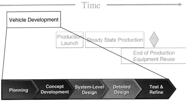
Like most product development projects, vehicle development includes planning, concept development, system-level design, detailed design, and testing and refinement (shown in Figure 2).5 Although they are somewhat related to the topic of this thesis, planning and concept development will not be deeply explored. This document focuses on the latter stages of the vehicle development process, namely the system level design, detailed design, and test/refinement stages.
Figure 2: Vehicle Development Mapped to Generic Product Development Process Vehicle Development lProduct l aState Product on Launch, End of Produvction DevelopEentpmsig Re e " .L-. - * .. _-_ _ _ _
System-level design includes a design of the overall architecture and decomposition of the vehicle into major sub-systems and components.6 Decisions in this stage begin to impact the design of the exterior fitting fixture that will be used in subsequent phases of the vehicle lifecycle.
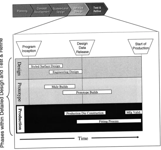
Development activity related to the exterior fitting fixture is most concentrated in the detailed design and testing/refinement phases. During the development of a vehicle, the detailed design and test/refine stages are comprised of three workstreams: design, prototype, and production and are illustrated in Figure 3.
Figure 3: Detailed Design & Testing/Refinement Activities a) C) Cc 0-'0 C C C) 0) CZ) \ProgramIncjeption Design Data
Release/ ProdulctioStartof
Time
The design workstream consists of styled surface and engineering design. Styled surfaces are the vehicle parts that the end customer sees, such as the doors, hood, and body sides. As the styled surfaces are being finalized, engineers begin designing all of the components and structural surfaces of a vehicle. The majority of this design work is completed in a Computer Aided Design (CAD) environment, and the final math-based
files are released in stages based on production tool lead-time requirements. The purpose of the staged release is to allow dies to be started as soon as possible, as opposed to waiting for the entire vehicle to be completed. Many of the components that are eventually mounted to an exterior fitting fixture, such as the body sides, hood, and fenders, are the last to have fabrication tools kicked off.9
While surface and component design is in the fine-tuning stage, prototypes are constructed and vehicle level development such as ride/handling is conducted. Prototypes are complete vehicles that are built before mass-production tools are
available.10
The production workstream begins when metal stamping dies, molds, and other
production tools are fabricated. As each die is completed for the first production parts to be stamped and/or assembled, the engineers attempt to reach a stable process within close range (approximately 3/4 of points measured) of specifications. Next, a fitting process is used to "tune-in" the production tools and dies. As production parts are produced, they are evaluated for functionality, and dimensional precision and accuracy. For exterior parts, this "tune-in" process benefits greatly from an exterior fitting fixture. More on this
subject is included in Chapters 3 and 4.
The fitting of parts can also continue into the vehicle assembly process validation stage, where manufacturing tools are also "tuned-in". At this point, the dies are typically the "home line", where they will remain for regular production. For the initial assembly events, LaPerre uses a pre-production facility and supplier facilities to begin the fitting process, and eventually moves the fitting activity to the vehicle assembly plant as manufacturing validation is ramped up. When the assembly plant starts running and
approaches the start of production date, the production launch process is initiated.
2.2 Production Launch
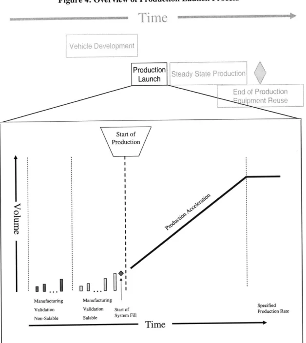
Toward the end of the vehicle development process, the manufacturing validation non-saleable production begins, followed by manufacturing non-saleable, start of system fill, and production acceleration. Although many other activities take place, a simplified version of these stages is depicted in Figure 4.11
Figure 4: Overview of Production Launch Process Production Launch Ado Pouction Rnn ReUs Start of Production Manufacturing Validation Start of Salable System Specified
Fill Production Rate
- Time
The goal of the launch process is to prepare the plant personnel and equipment for regular production at a pre-determined rate of vehicles per day. Typically, the first vehicles built
are considered non-saleable. That is, they are built with production tools and processes but do not meet the quality standards required to sell the vehicles to consumers. The
following build - manufacturing validation saleable - is for vehicles that can be sold to
0
I I...'I Manufacturing Validation Non-Salable
consumers, assuming that any major issues from the non-saleable batch were resolved. During non-saleable builds, a small number of exterior fitting issues are typically being resolved, and minor continuous improvements to the exterior may continue into
subsequent stages.
When the start of system fill is initiated, the vehicle development process is effectively complete, and all of the required raw materials, sheet metal, and subassemblies fill the supply pipeline that extends from each station in the assembly plant to supplier facilities to material sources. Movement of that material is increased as the rate of vehicle production is ramped up. Upon completion of ramp-up, the line runs at a specified production rate, and the launch process is complete.
2.3 Steady State Production & End of Production
Steady state production is commonly referred to as "regular production". At this point, the focus is on continuous improvement and resolving any potential issues that may arise from unexpected equipment issues or supplied material defects. Regular production typically extends for several years until production is discontinued or additional options and features are added to the vehicle. At the conclusion of the vehicle's production life, much of the equipment, including exterior fitting fixtures, is recycled or reused on future vehicle programs.
2.4 Chapter Summary
This chapter provided an overview of a generic vehicle development process. It divided the process into vehicle development, production launch, steady state production, and end of production/equipment reuse. Throughout each of these phases, different activities take place that impact the quality of vehicle exterior fits. This understanding of the overall process provides a structure in which to introduce more detailed processes and tools discussed in Chapter 3.
Chapter 3 - Exterior Fitting Tools & Processes
In order to understand an engineering system that utilizes an exterior fitting fixture, it is helpful to understand their purpose and how they are used. This chapter also lays out
some of the challenges inherent in vehicle dimensional management.
3.1 Purpose of Exterior Fitting Tools
The primary objective of exterior fitting tools is to verify and ensure that exterior
dimensions that consumers care about most are within an acceptable range. The exterior dimensions that are considered critical are all part-to-part interfaces that a customer would see. For example, the gap between a hood and fender is shown in Figure 5. The
consistency and closeness of the gap projects an image of craftsmanship that is required to excite many customers and to compete in large segments of the automotive market. Another feature that is important to the look and feel of the vehicle's quality is alignment of mating parts. Figure 5 shows how good alignment at the intersection of the fender, hood, and A-pillar contributes to the overall flow of the vehicle's shape. For this reason, the gaps between parts are measured and tracked closely throughout vehicle development
and production.
Figure 5: Example of Excellent Hood-to-Fender-to-A-pillar Fit
Smooth transition at hood/fender/A-pillar intersection Tight and consistent hood-to-fender gap.
Several categories of dimensions exist. However, gap and flush are what many customers notice. This widely accepted view on exterior fits is summarized in this Quality Magazine quote: "The size of the gaps between body panels such as the hood and fenders, fenders and doors or deck lids and quarterpanels are increasingly scrutinized by consumers. The flushness of adjacent body panels is closely examined as well. These body fit characteristics not only affect customer perceptions of vehicle quality, but they also affect warranty claims for issues such as water leaks and wind noise."12
Lee and Thornton use the term Key Characteristics (KCs) for product features,
manufacturing process parameters, and assembly process features that significantly affect a product's performance, function, and form.13 Gap and flush of vehicle exterior parts are Key Characteristics, and warrant special attention throughout the development process. Figure 6 provides a sample illustration of gap and flush.14
Figure 6: Gap & Flush Illustration
flush
fender
door
gap
At LaPerre, tolerance ranges for gap and flush are specified early in the vehicle
development process and are followed closely throughout the vehicle lifecycle with both computer aided design tools and fixtures. Before examining LaPerre's change initiative, Section 3.2 will explore general methods to track and measure dimensional progress of a vehicle throughout the vehicle lifecycle.
3.2 Exterior Dimensional Tools
Exterior dimensional tools can be divided into four main categories: 1) virtual (CAD) tools that verify design, 2) measurement tools that take a sample of discrete
measurements or scan entire parts to verify dimensions with a computer representation of physical parts, 3) online production laser gauges, and 4) fixtures (exterior fitting) that
allow measurement and/or visual evaluation of physical parts.
CAD tools are widely used to both execute and verify design intent. For example, at General Motors, a virtual build event to evaluate assembly interfaces is completed before physical prototypes are available.15 The second category of dimensional tools is a
combination of physical and virtual spaces, in that actual parts are scanned and either evaluated against the part's CAD model or assembled with other scanned parts in a computer environment.16 Online production gauges have historically been physical measurement fixtures, but today consist mostly of laser gauges that help monitor dimensional variation during production. This thesis focuses on earlier stages of the vehicle lifecycle, where both CAD and other virtual tools are extensively used today. As computer-based tools mature, the need for fitting fixtures may decrease in the future. However, today (and likely for several years to come), fixtures provide significant advantages and continue to be a critical component of successfully developing and launching vehicles at LaPerre.
Exterior fitting fixtures are used to evaluate Key Characteristics of exterior parts, such as panel-to-panel fit (e.g., door-to-fender, door-to-door) and interfaces between parts such as lamp-to-hood and lamp-to-fender gaps. As production dies are fabricated, an iterative process is used to "tune-in" the dies and/or assembly tools to produce parts that are dimensionally acceptable (i.e., deliver the appropriate Key Characteristics). Detail fixtures are used to measure components at stamping facilities and other supply houses, and assembly check fixtures are built to measure dimensions of subassemblies such as a door or hood. What makes a fitting fixture unique, however, is its focus on the Key Characteristics of gap and flush on the vehicle, whereas other types of fixtures focus on the measuring or assembling of components and subassemblies.
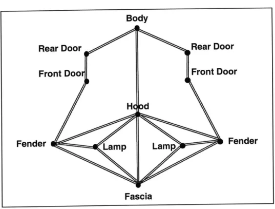
The importance of having a tool like this can be illustrated through an analysis of the Key Characteristics of a vehicle exterior. To start, consider the KC of the gap between a front and a rear door of a vehicle shown in Figure 7. The KC can be illustrated in a simple
diagram, with the double (red) line representing that a KC relationship exists between the front and rear doors.'7 If during the fitting process the gap is initially too small, the front door could be adjusted forward. However, moving the front door forward will impact the gap between the front door and the fender. The case where addressing one KC impacts another is called a Key Characteristic conflict.1 8 This conflict is shown in Figure 8. According to Whitney, one way to resolve a KC conflict is to alter the assembly
sequence. Typically, automotive exteriors are built from the back forward, which in this case might seem to resolve the KC conflict by allowing the assembly process to simply shift the fender forward. The fender is adjacent to several other parts, however, with additional and highly integrated Key Characteristic relationships that are shown in Figure
9.
Figure 7: Front to Rear Door Gap Key Characteristic
Front Door Rear Door
KC
-Figure 8: Key Characteristic Conflict
Figure 9: Vehicle Key Characteristic Conflicts Bo Rear Door Front Door Hd Fender Lamp Fas Rear Door Front Door d Lamp Fender
It is not possible to solve the KC conflicts in Figure 9 with any assembly sequence. If the front door is too close to the fender, moving the fender will impact three other KCs. The
cycle continues and any variation that is transferred along the chain will impact multiple KCs. This is perhaps one reason why auto manufacturers cite numerous vehicle launch
Fender Front Door Rear Door
issues related to lamp fits. Complicating the matter even further is the part-to-part flushness requirement, a second KC between the same KC nodes in Figure 9 that may be in conflict with gap KCs.
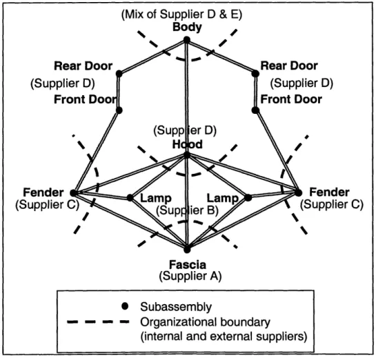
The supply chain of each subassembly and their respective components increases the difficulty of ensuring all KCs are delivered. At LaPerre, the doors, fenders, and hood are supplied internally for most vehicles, and different venders are used for lamps, fascias, and often times assembly fixtures for each exterior part subassembly. This makes resolving potential design and quality problems more difficult during validation and launch phases, because each supplier is focused more on their own parts than the entire assembly. This fragmentation is shown in Figure 10.
Figure 10: KCs that Typically Cross the Supply Chain
(Mix of Supplier D & E)
Body
Rear Door Rear Door
(Supplier D) (Supplier D)
Front Doo Front Door
. (Supp er D)
Fender Lamp Lam Fender
(Supplier C) Lamp Lamp (Supplier C)
Fascia (Supplier A)
S Subassembly
- - - - Organizational boundary
KCs that cross organizational boundaries increase the challenges of coordination.
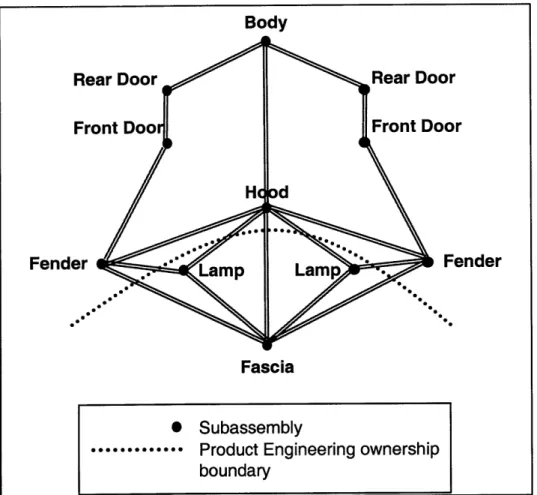
Perhaps an even greater management challenge arises from segmented ownership. In the past, KC design ownership at LaPerre was not allocated to a single person until very high levels of management. This engineering ownership boundary is illustrated in Figure 11.
Figure 11: Product Engineering Ownership Boundaries across KCs
Body
Rear Door Rear Door
Front Doo Front Door
Fender Lamp Lamp Fender
Fascia
* Subassembly
Product Engineering ownership boundary
This investigation into gap and flush characteristics has shown that vehicles are very sensitive to dimensional errors, because significant errors can propagate throughout the vehicle's system without an available "exit" from the KC chain. Identifying and isolating potential KC fit issues early is critical to successfully launch a new vehicle. The use of a fitting (cubing) fixture can help facilitate this process.
Exterior fitting fixtures enable the "tune-in" process by simulating nominal attachment points for certain subassemblies, and also may include a simulated portion of the surfaces adjacent to the subassembly under evaluation. For example, Figure 12 shows an exterior fitting fixture to evaluate the KCs around a single tail lamp from a Skoda Octavia Combi.19 The manufacturer of this fixture refers to it as a single-purpose cubing fixture, and the cost is estimated at $20K - $40K. 0 The single-purpose cube allows evaluation of how well a lamp fits with simulated surfaces that are adjacent (e.g., deck lid, body side, and fascia). The precision-machined aluminum parts represent design-nominal and are referred to as control parts. The advantage of this tool is that one can evaluate Key Characteristics such as gap, flush, and overall appearance visually and follow up on any potential issues with a measurement gauge. A single-purpose cube does have limitations in that it only looks at one part in isolation, which represents only one side of the gap.
Figure 12: Single Part Exterior Fitting Fixture
Lamp under Simulatedattachment
evaluation points and:
1. body side
2. deck lid
3. rear fascia
Similar to the single-purpose cubing fixture is another type of exterior fitting fixture that is larger and contains provisions for more than one production part. One fixture vendor calls this a partial cubing fixture, and the cost is estimated at $200K - $400K. 1 It includes, for example, attachments for production parts for the entire front end of a vehicle (e.g., lamps, fascia, etc.). A partial cubing fixture contains machined aluminum
of a partial cubing fixture used in the exterior fitting process for a Volkswagen Golf is shown in Figure 13.2 In Figure 13, the partial cubing fixture is also equipped with control parts than can be interchanged with production parts. Therefore, gap and flush can be evaluated between production parts (part-to-part) or between production parts and control surfaces (part-to-control).
Figure 13: Partial Cubing Fixture - Front End
Simulated adjacent fender Attachment
points for. exterior parts vehicle front end
A similar concept can be extended to a fixture representing the full exterior of a vehicle. This thesis will refer to this type of fixture as a vehicle cubing or fitting fixture, and an example is depicted in Figure 14.23 The cost of a vehicle cubing fixture can be as low as $250K and as much as $1,300K with a complete set of control parts.
Figure 14: Full Vehicle Cubing Fixture
3.3 Pros and Cons of Exterior Cubing Fixtures
Given that cubing fixtures can cost over a million dollars, why would automakers use them? The answer is that it allows visual evaluation of Key Characteristics as soon as the first production parts are available. Key Characteristics are often in conflict with each
other and involve multiple organizations within auto companies and across organizational boundaries into the supply chain (see Figures 10 and 11). Many detail part and
subassembly fixtures are used in vehicle development and production, but a cubing fixture focuses product development and manufacturing teams on what matters to customers in terms of exterior fit, and ultimately perceived quality.
Historically, a high number of difficult vehicle launch issues are related to gap and flush or "part fit" Key Characteristics.24 A fitting fixture can reveal problems that would cost exponentially more to solve in later stages of vehicle development and production launch. If fitting fixtures were not available to engineering teams, they would have to wait for a dimensionally acceptable body structure (i.e., exterior part mounting points) to even
with today's aggressive launch schedules, the start of production would likely be delayed. By providing a root-cause finding tool for dimensional issues, cubing fixtures speed up the iterative problem solving required to produce fabrication tools and setup assembly lines.
In conjunction with exterior fitting is a process whereby sheet metal subassemblies, and eventually an entire body, are fastened together with screws. These bodies are commonly referred to as "screw bodies".25 The screw body build also enables dimensional
evaluation earlier in the production development process, before production weld tools are ready. Throughout the screw body evaluation, comparing results from the screw body to a cubing fixture can help isolate the root cause of dimensional deviations. Cubing fixtures can also be used for problem solving in later phases of development and regular production.
The disadvantage of exterior fitting fixtures is mainly cost, which includes more than just the initial design and construction costs. Because cubing fixtures are designed and built while some of the vehicle design is changing - albeit to a lesser extent than early
development phases - the fixtures themselves must be maintained to stay current with the vehicle design. In addition to the added cost of fixture modifications, project
management time is required to track and manage changes to cubing fixtures.
3.4 Chapter Summary
This chapter presented the concept of Key Characteristics, challenges of managing KCs, and three types of fitting fixtures to help evaluate vehicle exterior KCs. The main vehicle exterior KCs are gap and flush. The three types of fitting fixtures are single, partial, and vehicle cubing fixtures. Several pros and cons of each fixture were also discussed. These fixtures are one piece of what it takes to successfully deliver vehicle exterior KCs. The issue is that KCs are interrelated and often times conflict if adjustments are needed. Also, because the KCs represent the interface between parts rather than the parts
combined with the awareness of different build strategies in Chapter 4, helped the author to better evaluate and contribute to the fitting fixture initiative at LaPerre.
Chapter 4 - Build Strategies
A build strategy is the process that automakers devise to validate, buyoff, and launch an assembly process for a new vehicle. Over the past 20 years, much attention has been paid to the build strategies used by Japanese companies. Global competitors, especially in the U.S., have worked to learn Japanese build strategies in an effort to improve their own systems. As a result of this research by U.S. companies, two broad categories of build strategy have emerged as common language at automotive companies. The goal of this chapter is to explain the two philosophies, as they impact design decisions of exterior fitting fixture. An understanding of these strategies will also help to shed light on some of the challenges auto manufacturers including LaPerre have faced (detailed in Chapter 5) in their continual quest to launch high quality vehicles faster and at lower costs.
4.1 Net (nominal) Build Philosophy
Net (or nominal/build-to-print) build philosophy is the more traditional of the two build strategies, and is conceptually simpler to understand and manage with business systems. The traditional approach to ensuring assemblies meet a certain dimensional specification is to first validate that each component and subassembly produced meets design
specification. Stated simply, perfect parts (i.e., close to nominal and in the tolerance band) should assemble into perfect assemblies in a net build world. One key assumption to this, however, is that the component parts are rigid, and therefore their dimensions are not changed by the assembly process.
In the automotive industry, component parts are not all rigid. According to one research study, 37% of vehicle assembly processes involve non-rigid parts.26 Therefore,
dimensions of many parts change as they are seated into fixtures, clamped, and then welded. Also, while the net build approach is easier to conceptually understand and manage with engineering approval systems, history has shown that this approach can make it difficult, if not impossible, to meet timing and cost objectives. Critics point to
the fundamental flaw that net build focuses decisions on optimizing parts, rather than assemblies that customers ultimately see.
4.2 Functional Build Philosophy
Over the last decade, Daimler-Chrysler Corporation, Ford Motor Company, and General Motors Corporation have studied the functional build strategy based on learnings from
27
other automakers. LaPerre Motor has also implemented a functional build approach at various levels of the organization. This section summarizes the main elements of functional build as outlined by the Auto/Steel Partnership Program, the University of Michigan Transportation Research Institute's Office for the Study of Automotive Transportation, and the Author's research at LaPerre Motor.
Functional build takes a holistic approach to validating, approving, and launching manufacturing processes for new vehicles. Rather than focusing on getting 100% of the components within design specification, this approach focuses on consistently building acceptable assemblies, as defined by Key Characteristics. If the mean values of most component parts are within design specification, the theory is that the ones out of specification might not negatively impact the dimensional quality of the vehicle
assembly. Another aspect of the functional philosophy is to consider all options that will accomplish the goal of making a good assembly, not just reworking all dies for
components that do not meet specifications. There are several reasons why the
components that do not meet specification could still build into an acceptable higher-level assembly.
First, the design and assembly process could be robust enough to absorb variation. Two parts joined with a slip plane is an example and is shown in Figure 15. If one part is longer than expected, the overall length remains the same if assembled with the fixture shown. Another possibility is that, because several automotive assembly processes involve non-rigid components, parts are deformed into place such that the assembly
containing the "bad" part becomes dimensionally acceptable. An example of this is
shown in Figure 16.28
Figure 15: Slip Joint
KC
=
Length
Figure 16: Assembly of Non-Rigid Components
V
V2
t
With a functional approach, part one and part two from Figure 16 are assembled with a screw fastener or weld, and if the final variation Vf is within the assembly specification, the dies for part 1 and 2 are not reworked. This is the case even if variations Vi and V2 do not lie in the specified tolerance band on their prints. In a functional build mindset, rather than asking if the component dies can be reworked, the relevant question is whether the stampings will repeatedly make similar parts and whether the assembly process can consistently fasten them with similar results. However, if a net build approach is used, both V1 and V2 are treated individually. If they do not meet the specification, the dies are reworked, adding potentially unnecessary time and cost in the fitting process.
A third scenario is where a dimensional discrepancy may require some die rework, but engineers have flexibility in which part to modify. For example, Figure 1729 shows the Key Characteristic of two weld flanges in an assembly that should ultimately have a gap equal to 1.0 mm. For simplicity this example will assume a tolerance band of zero. A nominal outcome is depicted in case A.
Figure 17: Illustration of Functional Build
A) Nominal, KC of 1.0 mm gap achieved
Part A Part B
Nominal Nominal
B) Part B outboard, KC of 1.0 mm gap not achieved
PartA PartB
Nominal Outboard 1.0 mm
C) Part B outboard, KC of 1.0 mm achieved
Part A Part B
Outboard 1.0 mm Outboard 1.0 mm
Now, let's assume that the dies fabricated the parts such that part B is outboard 1.0 mm as show in case B. The KC is 1.0 mm away from the target value. With a net build approach, the die for part B would be reworked. With a functional approach, however, several options exist. One is to choose the die with the lower rework cost or shorter lead time. Case C shows the result if the most efficient one to rework were the die for part A. Another potentially feasible solution to case B is to adjust assembly tooling to move either part A, B, or both inboard.
so in a stable process. As with all cases where a deviation in a component is accepted however, care must be taken to understand potentially negative impacts to the assembly process or other areas of the system in which the part is utilized. This requires
communication with and approval from downstream users.
4.3 Functional versus Net
The Net build approach was challenged by the U.S. auto industry when research in the late 1980s at Japanese automakers suggested that reworking every die to produce perfect components was not the most cost-effective approach, nor did it guarantee a high quality assembly.3 0 Net build was considered high-cost because it drove unnecessary and expensive die rework. Often times, adjusting assembly tooling is viewed as lower cost, and sometimes no adjustment is even required.
Functional philosophy is very pragmatic, in that it asks the relevant question of whether a component has the potential to build a correct subassembly, or whether a subassembly has the potential to build into a correct assembly. At the same time, functional decisions involve very complex systems and can require more subjective judgment. Net build is very objective and therefore conducive to a system of checks and balances that is fairly straight forward to manage once established. Functional build requires close
coordination across multiple assemblies. Coordination within the organization is also needed. Documentation often becomes out-of-date, and without involvement from the original design engineers, opportunities to learn and improve future designs are lost.
Increasingly, another problem has arisen at LaPerre related to coordination of functional decisions. As the number of models from each manufacturer increases, more and more parts and subassemblies are shared across different vehicles. For example, a door that is used on one sport utility model may also be used on three other SUV models, saving design and manufacturing costs. Functional decisions made on the door subassembly of one model might not be appropriate for the other three. Compounding the issue is the lack of or sometimes inadequate documentation to track what and why functional
decisions are made. Key Characteristic tradeoffs involving functional decisions on one vehicle are complex enough without having to consider how KCs may be impacted on completely separate vehicles that will be built in the future.
Organizationally, functional decisions extend across several areas of expertise, such as body shop tooling, hemming, dies, and fixtures. Functional decisions for a vehicle also extend to other subsystems such as lamps, grilles, fascias, and glass. Many of these subassemblies even cross over to other organizations in the supply chain. In many companies, engineers are often encouraged to specialize and stay in one area for long periods of time, if not for their whole career. These engineers that have specialized so deeply may be ill-equipped to make sound functional build decisions.
From a timing standpoint, it is unclear if the functional build approach is superior to net build for all vehicle programs. Proponents of functional build, such as Center for
Automotive Research (CAR) members, compare the long lead time of reworking dies to the shorter timeframe of making assembly adjustments in the body shop.3 1 One study by a different group at the University of Michigan found that die tryout time (part of the die construction and fitting process in Figure 3) can be reduced up to 90%.32 Researchers that advocate the virtues of functional build do admit there are tradeoffs. They point to the inherent drawback of functional build in that it is a downstream activity, because all components in an assembly (i.e. the entire KC chain) must be manufactured before the functional build can take place.33
4.4 A Build Strategy Framework
In this section, a framework is proposed to summarize how functional build decisions may be applied. Another goal of the framework is to communicate how functional build
is related to product structure. Finally, this model can also help to explain key design decisions for an exterior fitting fixture at LaPerre.
Before exploring functional build decisions, it is helpful to summarize the four functional build scenarios as show in Table 1.
Table 1: Functional Build Scenarios Build Scenario Description
1. Robust Design "Out of spec" condition does not impact Key Characteristic 2. Non-Rigid Parts Assembly process deforms the parts back into specification or an assembly conforms to non-rigid parts enough to meet KC requirements of assembly
3. Efficient Solution Error impacts KC of assembly, but have flexibility in choosing which die or assembly tool to change 4. Luck Errors cancel each other out
All four scenarios are based on the assumptions that the assembly process can either absorb or compensate for a part that is originally out of the designed tolerance band, and that the consumer cares about getting a good assembly, not necessarily a vehicle with parts that are made exactly to an engineer's print.34 By common sense, the latter assumption is likely true, the former is not as easy to assess.
Recall that in order for an assembly process to absorb mean deviations of components or subassemblies, parts must be compliant or contain slip-plane joints. Some sheet metal components are neither rigid nor designed with slip planes, and the net build approach is most appropriate. Similarly, if gross errors are discovered in stamped components, then it is clear that dies should be reworked. Perhaps a less clear application of which build strategy to take is when non-rigid components are assembled and become a more rigid structure as a subassembly. As rigidity increases, the ability of the assembly process to absorb mean deviations decreases. The framework presented in Figure 18 illustrates this concept. The model applies to sheet metal, and although other parts have not been the
focus of most build strategy literature, the framework also encompasses lamps, trim parts, and other exterior parts or assemblies.
Figure 18: Functional Build Implementation Framework
Deviation from Print Acceptable? Functional Build Scenario Not Likely Fewer Cases Some Cases 1 1,3,4 1,2,3,4 Vehicle I -Subassembly Subassembly Smaller Subassembliel Components
The key point of Figure 18 is that the functional build strategy has limits in how it can be applied. In addition to the concept of rigidity, the concept of complexity is introduced. Complexity in this context increases, because KC chains become larger as components are built into subassemblies. Also, KC chains become more interconnected as
subassemblies are built into the final assembly. Therefore, the likelihood of a functional build option decreases at higher levels of the vehicle assembly structure. At the vehicle level, gaps can be viewed as a series of butt joints between rigid parts. In this sense, the vehicle level build is essentially a nominal approach. Including a nominal approach in a functional build model may appear counterintuitive at first. However, the functional build model here could be viewed as a hybrid approach. Essentially, functional build
4A (D
E
00
065nominal build (reworking dies) is certainly an option that is also included in functional build.
The model is valid for subassemblies that contain all compliant parts or a mix of rigid and compliant components and is divided into three regions - some cases, fewer cases, and not likely. What follows is an example hood subassembly that will aid in visualizing application of the model. The hood assembly process is shown in Figure 19.35
Figure 19: Sample Hood Subassembly
7
-u
Fewer Cases
Some Cases
The actual assembly sequence could vary from Figure 19, but the sequence shown is sufficient for this example. At the lowest level are the components, which include the
:2
hood outer, hood inner, and three reinforcements. Individual components are stamped, and then the reinforcements are welded to the hood inner. At the second level of the assembly, the hood outer is still not attached to other components. The final operation marries the hood outer to the inner in a hemming operation, where the edges of the hood are essentially wrapped around the edges of the hood inner/reinforcements subassembly. At each level, the rigidity content increases and the number of parts contributing the KC also increases. This does not mean that rigidity of individual parts (shown in Figure 20), such as the hood outer, increases. The intent of the model is to show that the average rigidity at each subassembly level increases. This is a direct result of structural shapes formed by joining parts.
Figure 20: Relative Rigidity of Hood Components
Hinge Reinforcenvnt Reinforcement Main Reinfomrnent Hood HoodInner Outer
To understand how the model applies to this example, let's examine the region in Figure 19 labeled some cases. This is the lowest level, where all four functional build scenarios (robust design, non-rigid parts, efficient solution, and luck) are a possibility. It is in the region of the assembly structure that in some cases, options other than reworking dies should be considered to address dimensional issues. In this stage of the assembly
process, consider the case where one edge of the main reinforcement extends in the cross-car direction beyond its tolerance band by 0.5 mm. In the robust design scenario,
sufficient clearance on the hood inner will allow the edge of the main reinforcement to be welded without impacting any Key Characteristics. Similarly, if clearances were not designed in the hood inner, perhaps the portion of the hood inner that would have interfered is also unexpectedly extended by the same or greater amount. This is the luck scenario, and since neither scenario impacts a KC, the deviation(s) from the print would be accepted. Had an interference existed that prevented assembly or impacted a KC, the efficient solution would require one of the two dies to be reworked.
At the second level of the assembly structure, consider the case where excessive die spring back has caused the hood outer to exceed the cross-car tolerance band by 0.5 mm. The non-rigid scenario applies very well here. If the hood inner/reinforcements
subassembly is close to nominal, the hood outer may conform through the assembly process, eliminating the need to rework the hood outer die. Perhaps an even greater influence on the final dimension is the assembly process, as Guzman and Hammett showed in one door assembly study.36 Regardless of how "good" the hood inner panel is, fixturing, clamping, welding, and hemming may contribute more to the final assembly dimensions than a component deviation.
Moving up the assembly structure to the subassembly level,fewer cases here provide opportunity for a functional build solution to a print deviation. The main reason is that the hood subassembly is now quite rigid. Therefore, the assembly process is less likely to cause "good" deformation, and the risk in waiting to find out rather than reworking a die is high. Nonetheless, the hood is not totally rigid and may deform during assembly, and correction via assembly is possible. Luck is also still a possibility if for example, in the
case of the 0.5 mm hood outer deviation, the mating fender is shifted in the same direction. Complexity has increases at this point in the assembly process. Other related KCs (like those shown in Figure 9) would have to be assessed in this scenario and would reduce the feasibility of accepting the hood and fender deviations. If a functional move
to the fender were possible, this also opens up the efficient solution options.
The final region in the model is the vehicle level, where the hood is assembled to the front end of a vehicle body. Here, a functional move entails the ability to change the location and/or orientation of the subassembly. The hood is rigid and can only be moved; it can not be changed. This region is labeled not likely because of the extent to which both Key Characteristics conflict and the KC chains interconnect.
It is important to note that the model is a general guideline based on the research of Daniel E. Whitney at the Massachusetts Institute of Technology and the many researchers at the University of Michigan's Transportation Research Institute. The model is intended to synthesize the overall scope of functional build. Another use of the framework is to aid in making design decisions for implementing an exterior fitting fixture.
4.5 Chapter Summary
This chapter defined two types of build strategies, nominal and functional, and then proposed a functional build framework. The framework combined the concepts of rigidity and complexity, and linked the two concepts to a set of functional build
scenarios, which include robust design, non-rigid parts, efficient solution, and luck. As an assembly is built up into subassemblies and eventually into the final vehicle, the model articulates which functional build options are most likely.
The functional build model considers both technical and organizational issues. From a technical standpoint, rigidity is a key theme. As the number of "bad" parts in a
in an assembly, the more coordination is required. As complexity increases in the KC chains, further organizational coordination is needed. Also, feedback on the feasibility of some functional decisions is not possible early in the validation process. For all these technical and organizational reasons, an increased number of functional decisions, in general, increases risk.
Through this understanding of the functional build strategy and KC analysis, the author was better able to assess LaPerre's past initiatives and understand the purpose of current initiatives that included the new fitting fixture. Using the functional build framework from Chapter 4, the KC analysis from Chapter 3, and the product development process from Chapter 2 as background, Chapter 5 explores the new fitting fixture initiative and both Chapters 5 and 6 further elaborate on organizational factors of successfully improving perceived quality at LaPerre.
Chapter 5 - Change Initiative
Chapter 1 introduced the competitive pressures in today's automotive market. The trend is for consumers to expect superior perceived quality, which includes (among other vehicle characteristics) consistent and tight gaps and flushness between exterior subassemblies. Recognizing this, all vehicle manufacturers have launched several initiatives to increase perceived quality over the past few years. In general, the industry has improved the perceived quality of vehicles a great deal. An additional effort to continue improving perceived quality at LaPerre was to improve their manufacturing validation process through a series of build events to identify and solve quality issues. This chapter outlines a portion of the improvement initiatives at LaPerre.
5.1 Motivation for Change
As quality expectation, product variety, and cost pressures have increased for
automakers, leadership at LaPerre has been on a mission to increase volume and quality of engineering output with the same (if not fewer) resources. The common theme when automakers needed to improve over the past 25 years has been to study Japanese firms to benchmark and copy their "best practices".37 The difficulty with this is that information is imperfect, and it is often difficult to quickly and fully understand and replicate the systems that make companies like Toyota so successful.
Rather than focus on other companies, LaPerre decided to benchmark their own internal divisions at each of their separate global regions. One high-ranking employee remarked, "We are studying who in our company are the best-of-the-best (BOB), copying whatever they do well, and implementing it worldwide." In their search to find the BOB in exterior fits, executives were fortunate to find a sister division that produced vehicles with gap and flush results that were far superior to the other divisions. As different LaPerre leaders visited and studied this division, the managers of the sister division repeatedly pointed to a fitting fixture when explaining their extraordinary ability to solve exterior fit
and tangible tool that could be copied and installed. Also, from a functional build standpoint, LaPerre leadership recognized that the functional build approach becomes a nominal build strategy at the subassembly and vehicle level (see Figure 18). The sister division's fitting fixture contained nominal control parts at the subassembly level, which further highlighted the nominal build strategy needed at higher subassembly levels.
5.2 The "New" Fixture
The tool at the sister division was a certain type of exterior fitting fixture. At the time, LaPerre used fitting fixtures for similar purposes. The main difference was the design of the fixture and how it was used.
On a typical LaPerre vehicle program, three exterior fitting fixtures were used. Using terminology from Chapter 3, LaPerre utilized two partial cubing fixtures and one full vehicle cubing fixture. The design of the partial cubing fixtures was similar to the one depicted in Figure 13 - one for the front and one for the rear of the vehicle. The full vehicle cubing fixture LaPerre used was similar to the one shown in Figure 14, but contained no control parts (simulated nominal surfaces), with the exception of head lamp "plug" gauges and a small number of control parts on some vehicle programs.
The partial cubing fixtures and full vehicle fixture at LaPerre were designed and managed by a mixture of organizational groups, and although the same vehicle team needed to use both fixtures, they were housed in different complexes. While there are several good reasons to use multiple fixtures housed in different locations, this can pose several problems for vehicle manufacturers when dimensional issues overlap multiple fixtures. The first problem is the potential for conflict between two fixtures. This can lead engineers to take time debating over which fixture is correct. Having fixtures located at multiple sites can waste valuable time as well. When team members have to compare results on one fixture to the other, they have to travel to multiple sites. Compounding the problem is the difficulty in transporting parts between the two sites. At several vehicle manufacturing sites, engineers are not permitted to carry parts into or out of a company
complex. The required procedure can involve an arduous process of filing the necessary shipping requests and then following the process. One engineer said, "It takes over a day of my time to make sure my parts don't get stuck somewhere at dock, on a truck, or lost."
The overall goal of a fitting fixture is to validate vehicle exterior Key Characteristics, and aid in the validation and trouble shooting process. The chain of KCs in a vehicle is an interrelated system, and the intent of a fitting fixture is to view the interdependencies as a total system. It is difficult to validate and troubleshoot the KC system when several fixtures, designed and maintained by separate groups, are housed in multiple locations. Figure 21 shows how existing fixtures relate to the exterior KCs of a relatively simple example vehicle.
Figure 21: Select Key Characteristics Mapped to LaPerre's Existing Fixtures Vehicle Cubing Fixture
The motivation for multiple fixtures at LaPerre is historical and primarily based on how they are organized. The engineering organization is divided into teams responsible for vehicle subsystems. The subsystem grouping aligns with how a typical vehicle assembly plant is organized. The three main sections of a plant are the body shop, paint shop, and general assembly. The body shop is where metal stampings are welded together to make a body-in-white (BIW). The BIW includes all of the sheet metal that makes up the body structure and exterior closure parts (door, hood, deck lid, roof, etc.). It is called a BIW before it goes to the paint shop. After the body is painted, the vehicle goes to General Assembly (GA) to get everything else (interior, chassis, lamps, fascias, exterior
mouldings, glass, etc.) installed. As a result, engineering teams are grouped into the BIW team and the GA team. In the past, it was not entirely clear who owned the KCs on the vehicle, because the ownership of designing and manufacturing the parts was separate. Single ownership of the KCs could only be found at executive levels of LaPerre's organization. To their credit, LaPerre recognized this as an area for continuous improvement and assigned owners to all KCs in engineering and manufacturing.
After learning of these organizational divisions that are common among automotive companies, it is not surprising that separate fixtures emerge from different teams and that the designs can be somewhat different. Until recently, the BIW cubing fixture at LaPerre did not include front and rear end subassemblies such as lamps and fascias. Recognizing the need to have a total vehicle approach was another step in the right direction to solving vehicle system issues. Multiple fixtures, however, still exist at many manufacturers, and the segregation of fixtures tends to focus attention on subsystems rather than the entire vehicle.
In contrast to LaPerre's fitting fixtures, the sister division utilized a single fixture. Also, a major difference was that it had a full set of control parts. That is, for each production part evaluated on the fixture, there was a corresponding control part representing a nominal surface. This tool had many inherent benefits over LaPerre's current fixture