HAL Id: cea-02339434
https://hal-cea.archives-ouvertes.fr/cea-02339434
Submitted on 20 Nov 2019HAL is a multi-disciplinary open access
archive for the deposit and dissemination of sci-entific research documents, whether they are pub-lished or not. The documents may come from teaching and research institutions in France or abroad, or from public or private research centers.
L’archive ouverte pluridisciplinaire HAL, est destinée au dépôt et à la diffusion de documents scientifiques de niveau recherche, publiés ou non, émanant des établissements d’enseignement et de recherche français ou étrangers, des laboratoires publics ou privés.
Creep and damage anisotropies of 9%Cr and 14 %Cr
ODS steel cladding
T. Jaumier, L. Vincent, S. Vincent, R. Desmorat
To cite this version:
T. Jaumier, L. Vincent, S. Vincent, R. Desmorat. Creep and damage anisotropies of 9%Cr and 14 %Cr ODS steel cladding. Journal of Nuclear Materials, Elsevier, 2018, 518, pp.274-286. �cea-02339434�
Creep and damage anisotropies of 9%Cr and 14%Cr ODS steel
cladding
T. Jaumier1,2, S. Vincent3, L. Vincent1, R. Desmorat2
1
DEN-Service de Recherches Métallurgiques Appliquées, CEA, Université Paris-Saclay,
F-91191, Gif-sur-Yvette, France
2
LMT Cachan, UMR CNRS 8535, ENS Paris Saclay, Université Paris-Saclay, 61 avenue du
Président WILSON, F-94235 Cachan cedex, France
3
DEN-Service de Technologie des Composants et des Procédés, CEA, F-13108, Saint-Paul Les
Durance, France
thibaud.jaumier@cea.fr
(corresponding author)
sebastien.vincent@cea.fr
ludovic.vincent@cea.fr
desmorat@lmt.ens-cachan.fr
Abstract
Two Oxide Dispersion Strengthened (ODS) steel tubes, obtained by means of hot extrusion and cold rolling, are studied as potential materials for cladding applications in sodium-cooled fast reactors. A 9%Cr martensitic tube (Fe-9Cr-1W-0.3Ti-0.25Y2O3) with isotropic microstructure is compared to a
14%Cr ferritic tube (Fe-14Cr-1W-0.3Ti-0.25Y2O3) with elongated grains and a strong texture. Tile and
notched ring specimens are used to perform uniaxial creep tests at 650°C in the longitudinal and transverse directions of the tubes. The 14%Cr ODS steel tube exhibits strong mechanical
anisotropies, while the 9%Cr presents only a slight anisotropy in creep resistance, presumably due to the influence of specimen geometry on mechanical fields. Both intergranular and ductile zones have been observed on the fracture surfaces of the uniaxial creep specimens, suggesting the competition of two damage mechanisms. Damage for both tubes appeared anisotropic, with orientated cracks in the rolling directions on the ring specimens and the 14%Cr tile specimens. Internal pressure creep tests also performed at 650°C show complementary results for both tubes in agreement with ring specimens’ ones, validating their use for hoop properties assessment. Overall, while the 14%Cr ODS steel tube is strong in the longitudinal direction, the 9%Cr tube proves as resistant in the transverse direction.
1. Introduction
The development of advanced nuclear systems such as Gen. IV sodium cooled fast reactors relies upon the availability of reliable structural materials. Oxide Dispersion Strengthened (ODS) steels are suitable candidates for fuel cladding applications due to low irradiation induced swelling [1,2], good creep strength [3–6] and corrosion resistance [7].
ODS steel tubes are mainly obtained by mechanical alloying steel with yttria powder and
consolidating the result by hot extrusion, followed by cold-pilgering punctuated by intermediate heat treatments to allow a reduction of the material hardness [8–10]. These different steps and the chemical composition of the material, in particular the chromium content, determine the resulting microstructure. For alloys with chromium content below 12% Cr, there is a phase transformation above 850°C and isotropic martensitic or ferritic microstructure can be obtained after the phase transformation. For alloys with chromium content above 13% Cr, there is no phase transformation;
only ferritic microstructures can be obtained [11]. Furthermore, abnormal grain growth leading to reduced mechanical properties at recrystallization temperatures (1400°C) for high chromium ferritic ODS steels makes such treatments difficult to control [1,12]. The resulting anisotropic microstructure with elongated grains in the rolling direction and a strong texture lead to anisotropic mechanical behaviour for high chromium ODS steels [5,13–15], with poor transverse properties compared to longitudinal ones. This is a concern for the cladding applications as the main solicitation is internal pressure creep due to fission gas building up inside the tube, loading it mainly in the hoop direction [16]. However, higher chromium content has been shown to improve corrosion resistance in ODS steels [17–19], another significant aspect for cladding applications.
Fewer studies [20,21] have been conducted on the mechanical properties of ODS steel tubes than on bulk material, owing in part to the difficulties or the costs surrounding the characterization of the hoop properties on a tube. However, they are necessary to study the material in its final form, having seen a different fabrication route than the bulk material; and to obtain crucial data on the creep lifetime of ODS steel tubes under thermomechanical loading.
In the present paper, results of creep tests performed on the axial and hoop direction of a 9%Cr and a 14%Cr ODS steel tubes are presented. The objective of this study is to evaluate the level of
anisotropy in the mechanical behaviour and creep resistance of the tubes and to eventually determine which batch might be the most relevant in the context of cladding applications.
A presentation of the different materials and characterization methods is first proposed, followed by a section in which experimental results, both on microstructure and creep tests, are exposed. A discussion of the results is then presented just before concluding the paper.
2. Materials & methods
2.1. Fabrication route and chemical composition
Metallic powders and yttria powder are mechanically alloyed under hydrogen atmosphere by Plansee, with the nominal chemical compositions: Fe-9Cr-1W-0.3Ti-0.25Y2O3 and
Fe-14Cr-1W-0.3Ti-0.25Y2O3.The milled powder is then degassed in a vacuum chamber at 400°C for 2h. Sealed in a soft
steel can, the powder is hot extruded into a rod at 1100°C. After drilling and straightening, the raw tube is manufactured into thin cladding tube using cold rolling passes in a HPTR mill, punctuated by intermediate heat treatments to reduce internal stresses. For the 9%Cr ODS steel tube, a
austenitizing heat treatment at 1050°C followed by helium quenching (3°C/s) is performed to achieve a martensitic state. Then, a final tempering treatment is performed at 750°C for 30 minutes. The chemical compositions of the final steel tubes (external diameter 10.73mm, thickness 0.5mm, length 2m), as analyzed by Bureau Veritas, are shown in Table 1. Abnormally high Ti apparent content is under investigation.
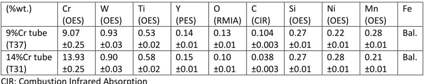
Table 1: chemical composition of the studied ODS steel tubes (%wt.) Cr (OES) W (OES) Ti (OES) Y (PES) O (RMIA) C (CIR) Si (OES) Ni (OES) Mn (OES) Fe 9%Cr tube (T37) 9.07 ±0.25 0.93 ±0.03 0.53 ±0.02 0.14 ±0.01 0.13 ±0.01 0.104 ±0.003 0.27 ±0.01 0.22 ±0.01 0.28 ±0.01 Bal. 14%Cr tube (T31) 13.93 ±0.25 0.90 ±0.03 0.58 ±0.02 0.15 ±0.01 0.10 ±0.01 0.038 ±0.003 0.27 ±0.01 0.28 ±0.01 0.21 ±0.01 Bal. CIR: Combustion Infrared Absorption
OES: Optical Emission Spectrometry
RMIA: Reducing Melting Infrared Absorption PES: Plasma Emission Spectrometry
2.2. Microstructural Characterization and fractography
Specimens of the 9%Cr and 14%Cr ODS steel tubes have been prepared to allow the cross-section observation of the microstructure of the materials in both the longitudinal and transverse
orientations. These specimens were first mechanically polished and then submitted to
electropolishing. Various methods were used to analyze them: electron backscatter diffraction (EBSD) analysis, electron probe micro-analysis (EPMA) and energy dispersive X-ray spectrometry (EDS). Hardness measurements were also conducted on long/cross-sections of the tubes.
2.3. Mechanical Characterization
Uniaxial and internal pressure creep tests were carried out. Two types of specimen were used to assess the mechanical properties in the longitudinal (rolling) and circumferential directions,
respectively tile and ring specimens. The geometry and specifications of these specimens are shown in Figure 1, as well as the loading conditions for the ring uniaxial creep tests. Circumferential creep tests were also performed by directly imposing constant pressure in tube specimens. The
configuration of these internal pressure creep specimens with the holding arrangement used is also presented in Figure 1(c). The specimen is 280mm long, with 10.73mm outer diameter and a wall thickness of 0.5mm. Water flow in the fixtures (welded to the tube) manages the cooling of the specimen prior to its connection to the machine. The welds are located outside the furnace. A mandrel inside the tube reduces the amount of argon gas necessary to maintain high pressure. An argon gas flow around the specimen is also used to reduce external oxidation.
Figure 1: specimen geometries. (a) tile specimen; (b) ring specimen; (c) internal pressure specimen
Uniaxial creep tests were performed at 650°C (±5). Usual precautions (Teflon coatings, molybdenum disulfide [22,23]) to limit friction during the ring creep test were prohibited by the high temperature investigated. Internal pressure creep tests have been carried out on both materials at 650°C. Even if both ring and pressure creep specimens are classically used to evaluate the hoop properties of a tube, here they are both tested. Ring specimens, although cheaper in use, suffer in our case of the aforementioned missing precautions, leading to uncertain stress/strain distributions. The data from the ring tests will be presented as is, meaning the strain is obtained by the simple ration of the crosshead displacement (as measured by a LVDT) over the gauge length. Comparisons between the
two geometries will tell if the data from the ring tests is relevant, analyzed as well by FE simulations (see appendix). Finally, pressure creep has additional value for its representativity of the cladding thermomechanical loadings.
For these comparisons, the mean hoop stress in the tube has to be evaluated. The method used is based on [24]. The external pressure being negligible compared with the inner pressure, the mean stress tensor in the tube is expressed as:
𝝈 =𝑃𝛷𝑚 2𝑡 ( −𝜂 − 𝜂2 0 0 0 1 − 𝜂 0 0 0 1 2− 𝜂 + 𝜂2 ) (1)
where P is the internal pressure, Φm the mean diameter of the tube, t the thickness
and 𝜂 = 𝑡 𝛷⁄ 𝑚 a geometrical parameter. A second-order approximation in 𝜂 (as opposed to a first-order approximation, which correspond to the thin wall formula) gives the evaluation for the mean hoop stress in the wall of the tube:
𝜎𝜃𝜃 = 𝑃𝛷𝑚
2𝑡 (1 − 𝜂) = 9.73 𝑃 (2)
The mean hoop strain is obtained by dividing the evolution of the external diameter 𝛷𝑒𝑥𝑡 by the initial mean diameter.
𝜀𝜃𝜃 = ∆𝛷𝑚 𝛷𝑚(0)≈ ∆𝛷𝑒𝑥𝑡 𝛷𝑒𝑥𝑡(0) − 𝑡 (3)
3. Results
3.1. Microstructure of the studied 9%Cr and 14%Cr ODS steel tubes
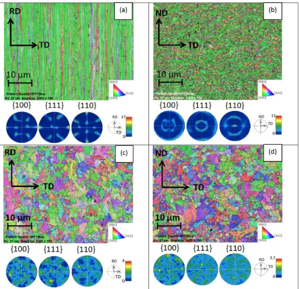
The results of the EBSD analysis are shown in Figure 2. The 9%Cr ODS steel tube exhibits grains of equiaxed shape, the diameter of which is around 5 micrometers, as shown on both the longitudinal section (Figure 2 (c)) and the cross section (Figure 2 (d)) of the tube. RD corresponds to the rolling direction, TD being the transverse direction and ND the corresponding normal direction. The pole figures and orientation maps of both sections also suggest an almost isotropic texture, but with a slight orientation of the <110> direction parallel to RD and the <111> direction to ND in the (RD-TD) plane. This type of microstructure can be seen on other martensitic ODS steels obtained at CEA [21,25]. Hardness measurements on long and cross sections of the tube give a mean value of 340HV (±12) with no significant differences between samples.
The 14%Cr ODS steel tube exhibits elongated grains in the rolling direction. These grains have an average diameter around 500 nanometers and an average length of 350 micrometers. They show a strong α texture, as the <110> axes of the grains are mostly aligned with RD and the <111> axes with TD, as seen in Figure 2 (a) and (b). Hardness measurements give a mean value of 372HV (±26), again with no significant differences between long and transverse samples.
Figure 2: pole figures and orientation maps obtained by EBSD analysis. (a) 14%Cr longitudinal section, (b) 14%Cr transverse section, (c) 9%Cr longitudinal section, (d) 9%Cr transverse section
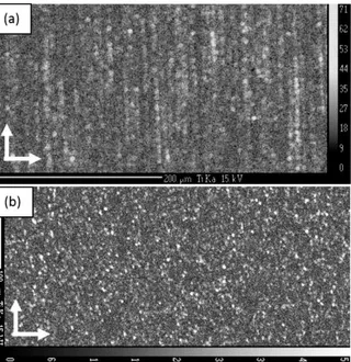
Other studies focus on particle size, composition and distribution in comparable ODS steels [4,26– 29]. Here, the only relevant information pertaining to potential anisotropies is the fact that titanium rich particles tend to gather and align along the grains of the 14%Cr steel tube in the rolling direction, as seen with the dark dots in Figure 2. EPMA also reveals this feature, as seen in Figure 3. This is a known feature of ferritic ODS steels [3,15,30,31] and is also observed on 11%Cr martensitic ODS steel with residual ferrite [32].
Figure 3: Titanium distribution (EPMA) in 14%Cr ODS steel tube. a) (RD-TD) plane; b) (ND-TD) plane
3.2. Creep tests
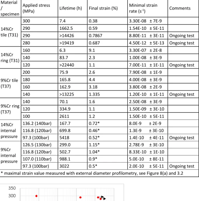
Creep tests have been performed at 650°C (±5) for both ODS steel tubes. Table 2 summarizes the creep properties of these alloys regarding lifetime, final strain and minimal strain rate (as a clear steady state cannot be observed for several tests). Pressure creep tests have been analyzed
according to equations (2) and (3). The data suggests a strong anisotropy between the longitudinal and the transverse direction for the ferritic 14%Cr ODS steel tube concerning creep strength, as also seen in Figure 4. For similar lifetimes, the tile specimens withstand a 150 MPa higher stress.
Table 2: Creep data for tests at 650°C Material
/
specimen
Applied stress
(MPa) Lifetime (h) Final strain (%)
Minimal strain rate (s-1) Comments 14%Cr tile (T31) 300 7.4 0.38 3.30E-08 ± 7E-9 290 1662.5 0.59 1.54E-10 ± 5E-11
290 >14426 0.7867 8.80E-11 ± 3E-11 Ongoing test 280 >19419 0.687 4.50E-12 ± 5E-13 Ongoing test 14%Cr
ring (T31)
160 6.3 9.1 3.30E-07 ± 2E-8
140 83.7 2.3 1.00E-08 ± 3E-9
120 >22440 1.1 7.00E-11 ± 1E-11 Ongoing test 9%Cr tile
(T37)
200 75.9 2.6 7.90E-08 ± 1E-9
180 165.8 4.4 4.00E-08 ± 3E-9
160 162.9 3.18 3.80E-08 ± 2E-9
140 >13225 1.335 1.20E-10 ± 1E-11 Ongoing test 9%Cr ring (T37) 140 70.1 1.6 2.50E-08 ± 3E-9 120 334.9 1.1 1.50E-09 ± 3E-10 100 2611 1.2 1.50E-10 ± 5E-11 14%Cr internal pressure
136.2 (140bar) 167.7 0.72* 8.0E-9 ± 2E-9 116.8 (120bar) 699.8 0.46* 1.3E-9 ± 3E-10
97.3 (100bar) 5418 0.52* 1.4E-10 ± 4E-11 Ongoing test 9%Cr
internal pressure
126.5 (130bar) 299.0 1.15* 2.78E-9 ± 3E-10 116.8 (120bar) 502.7 1.04* 8.33E-10 ± 1E-10 107.0 (110bar) 988.1 0.9* 5.0E-10 ± 8E-11
97.3 (100bar) 3022 0.5* 2.0E-10 ± 5E-11 Ongoing test * maximal strain value measured with external diameter profilometry, see Figure 8(a) and 3.2
Figure 4: comparison of creep strength for the 9%Cr and 14%Cr steel tubes in the longitudinal and transverse directions performed at 650°C. Arrows denote ongoing tests.
Concerning the 9%Cr ODS steel tube, creep resistance seems less affected by the stress direction, but still with lifetimes for the tile specimens ten to a hundred times longer than that of the ring
specimens for similar applied stresses.
The results of the internal pressure creep tests are also presented in Figure 4, compared with the uniaxial creep results obtained on the ring specimens. There are obvious similarities between internal pressure and ring creep specimens when looking at creep lifetimes. The results seem to follow the same trend, except the 14%Cr ring at 120MPa again. This ongoing test will be investigated after specimen failure to see if the guiding rods between the crossheads did not generate unwanted friction and thus alter the overall results.
Looking now at creep behaviour of these materials, the minimal strain ratedata is plotted in Figure 5. Once again, a significant difference can be observed with the minimal strain rate of ring and tile creep specimens for the 14%Cr alloy. A much higher stress is needed in the rolling direction to obtain the same strain rate as in the transverse direction, and the apparent Norton power-law exponent is higher (n~125) in the long direction than in the transverse direction with ring specimens (n~35). Concerning the 9%Cr ODS steel tube, the data seems to align reasonably well for both directions, with an apparent stress exponent (n<15 and similar in both directions) lower than the one of 14%Cr tube. More similarities between ring and pressure creep data is observed in creep behaviour for both the 9%Cr and 14%Cr steel tubes, with results seemingly aligning, except the 14%Cr ring at 120MPa.
Figure 5: Comparison of the stress-strain rate relationship for the 9%Cr and 14%Cr steel tubes in the longitudinal and transverse directions, creep tests performed at 650°C
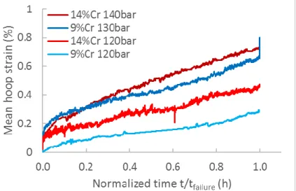
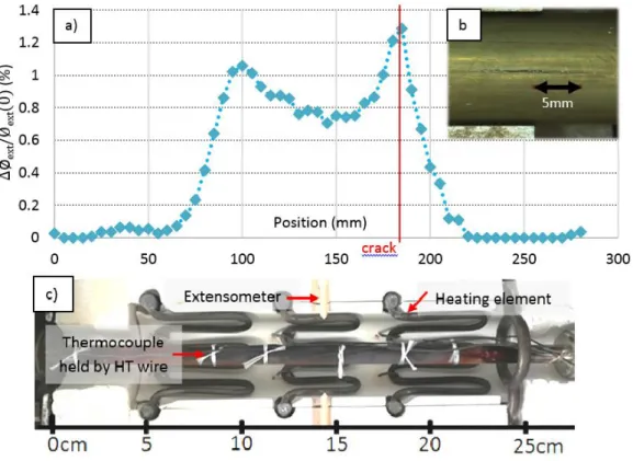
Remarkable creep features of ODS steels are low final strains and little or no tertiary creep, especially at low stresses [33–36]. This is observed here as well in Figure 6 with the creep curves for 9%Cr ODS steel tile specimens. This is particularly true for the pressure creep specimens (see Figure 7), with an apparent lack of tertiary creep stage, during which the strain rate would increase after the traditional steady-state creep. This usually manifests on tubes as a local bulging followed by burst. Here a single crack appears, a few millimeters in length, without significant local diameter change for the tube (total strain at failure around 1%), as seen in Figure 8. However, when comparing the evolution of the external diameter along the tube measured before and after testing, the deformation appears inhomogeneous, as shown in Figure 8a. This is due to temperature inhomogeneity along the tube, creating potential sites for strain localization leading to failure. The water-cooled fixtures on both ends of the tube lowers the temperature in the tube’s extremities, where no creep occurs (see Figure
8a). Inside the furnace, temperature is controlled with three thermocouples centered with the three heating elements, yet temperature variations may occur between them. This can explains the lack of apparent tertiary creep stage, since the extensometer is located at the center of the tube specimen, away from the localized deformation that evidently occurs at the end of the test.
Figure 6: Normalized creep curves of 9%Cr tile specimen tested at 650°C and 140-180MPa
Figure 8: internal pressure creep on 14%Cr tube at 650°C and 140 bar a) external hoop strain along the tube length; b) close-up of the crack after failure ; c) specimen inside the furnace
3.3. Fracture characteristics for uniaxial creep specimens
9%Cr ODS steel specimensObservations of the fracture surface of the creep specimens reveal the coexistence of two damage mechanisms, intragranular and intergranular, for both materials.
Figure 9(a) and (c) shows SEM observation of 9%Cr ring specimens (tested at 650°C and 140/120 MPa, lifetimes 70.1/334.9h), both exhibiting a similar pattern. On the outermost part of the ring, dimples can be seen, as well as evidence of tearing and minimal oxidation. Towards the inside, and affecting most of the fracture surface, features characteristic of intergranular decohesion can be seen, as well as much more oxidation.
Figure 10 highlights the intergranular decohesion that can be observed on the fracture surface of 9%Cr ODS steel tube tile specimen tested at 650°C/180MPa, 165.8h. These grains appear highly oxidized. Other regions only exhibit dimples, suggestive of ductile intragranular damage.
Figure 9: SEM observation of the fracture surface on ring creep test specimens of the 9%Cr ODS steel tube (RD=vertical); a) creep test 650°C 140MPa (inner part of the ring on the left); b) intergranular decohesion; c) creep test 650°C 120MPa (inner part of the ring on the right); d) dimples and oxidized intergranular decohesion
Figure 10: SEM observation of the fracture surface on a tile creep specimen of the 9%Cr ODS steel tube (180MPa, 650°C); magnification (a) x150, (b) x1000
In Figure 11, the SEM observation of a cross section of a tile creep specimen of the same 9%Cr ODS steel tube tested at 650°C/180MPa is presented. Extensive damage ahead of the main crack can be seen, with no apparent preferred direction for these micrometric cracks. When looking at ring creep specimens of the same alloy tested at 650°C/140MPa/70.1h, we can see in Figure 12 that cracks seem to align on the rolling direction.
Figure 12: SEM observation of a cross section on a ring creep specimen of the 9%Cr ODS steel tube; 650°C 140MPa 14%Cr ODS steel specimens
In
Figure 13, the focus is on the fracture surface of a 14%Cr ring tested at 650°C and 140MPa (lifetime 83.7h). The elongated shape of the grains is visible after what appears to be intergranular decohesion in stripes aligned with the rolling direction.
Figure 13: SEM observation of the fracture surface on a ring creep specimen of the 14%Cr ODS steel tube (RD=vertical); magnification (a) x200, (b) x1000
Figure 14 shows the fracture surface of a 14%Cr tile creep specimen, tested at 650°C and 290MPa, 1662.5h. Again, two types of damage can be seen on the surface, the brighter being the oxidized intergranular area (b), the darker one with ductile damage and minimal oxidation (c).
Figure 14: SEM observation of the surface rupture of a 14%Cr ODS tile specimen, creep test at 650°C and 290MPa. (a) x50; (b) dimples (x1000); (c) intergranular damage with oxidation (x1000)
In
Figure 15, SEM observations of cross-sections of tile and ring specimens reveal different damage patterns. For the tile specimen, the main fracture and some secondary ones occur perpendicular to the load, and cracks parallel to that loading direction can also be seen. For the ring specimen, only cracks perpendicular to the loading direction can be seen. This is typical of ferritic ODS steels with elongated grains [3,6,37–39], for which the grain boundaries, where titanium enriched unwanted particles tend to align as well, facilitate crack nucleation and propagation.
Figure 15: SEM observation of cross sections of 14%Cr ODS steel tube creep specimen. (a) tile specimen, 650°C 290MPa; (b) ring specimen 650°C 140MPa
Fracture surface observation on the creep ODS steel specimens, both tiles and rings, showed the presence of oxidized intergranular fracture zones and ductile zones. This has been observed on other 14%Cr bulk ferritic ODS steel [37], with the following proposed two-step crack propagation
mechanism: a slow stable intergranular crack propagation (suggested by the strong oxidation of such zones) followed by unstable ductile fracture as soon as a critical stress intensity factor is reached at the tip of the crack. Present observations concur with such fracture phenomena.
4. Discussion
4.1. Creep properties
Two types of mechanical anisotropies are observed on the studied ODS steel tubes, in addition to the microstructural anisotropic features of the 14%Cr ODS steel tube. First, a strong effect of the loading direction is seen in Figure 5 for the stress to strain rate relationship on the 14%Cr ODS steel tube, consistent with bulk ferritic ODS steels with similar chemical composition [37,38,40–44]. The 9%Cr ODS steel tube mechanical behaviour seems unaffected by the loading direction. The second anisotropic feature affects both tubes, even the 9%Cr one that both possesses an isotropic
stress is orders of magnitude lower for the ring specimens than the tile specimens. Tensile tests on a similar 9%Cr ODS steel tube with the same specimen geometries [21] also show a loss of ductility when testing the hoop properties with ring specimens. This is a known experimental artifact of the ring specimen: the relationship between the applied crosshead displacement and the effective strain in the gauge section of the ring has indeed been studied for different loading and material
configurations [45–48]. Finite element analysis is an efficient method to determine the mechanical properties from notched ring tests [47,49]. Early FE simulations on the ring specimen (in the chosen experimental set up) conducted in this study are consistent with the aforementioned studies (see Appendix), with the presence of high stress triaxiality on the inner part of the ring, at the center of the gauge section. This leads to early strain and damage localization in this region, resulting in failure of the ring at a misleading crosshead displacement misleading if one is to extract intrinsic material properties. A non-trivial effect of the specimen geometry is therefore suggested and would require further investigations for constitutive modelling and parameter identification for example. The idea would be to use the data from the 9%Cr ODS steel tube, believed to be isotropic. Although
martensitic/ferritic ODS steels with seemingly isotropic microstructure can present anisotropic damage mechanics due to the presence of Prior Particle Boundaries (PPB), artifacts of the powder consolidation process [32,50], no evidence of PPB pores could be found either in the as received 9%Cr tube or in the creep samples after rupture. In order to identify a mechanical behaviour and damage model, the data on the tile specimens could be used to obtain material parameters for the model and FE simulation on the ring geometry could then be performed to properly isolate the contribution of geometrical artifacts in the apparent anisotropy for this material. The study of the intrinsic material anisotropies of the 14%Cr tube could then be performed with a high confidence level.
Nevertheless, ring specimens in the chosen loading conditions seem adequate to produce data equivalent to internal pressure creep tests. The latter are the closest way to emulate the thermomechanical load that fuel cladding must withstand. However, they are costly (large
specimens), and fraught with technical difficulties: temperature homogeneity and pertinent strain measurement are the main ones encountered in this study. Comparing these results with uniaxial creep tests on notched rings, comparatively easier tests to set up and requiring less specimen
volume, confirms that the ring specimens are a good way to assess the hoop creep properties of ODS steel tubes, as the results on both specimens are quite similar (cf. Figure 4 and Figure 5). A possible suggestion is that the multiaxial stress state in the rings somehow emulates the biaxial stress of the pressured tubes, leading to comparable data. This is of particular interest for the characterization of irradiated claddings, where limited material can be put in experimental reactors, and ring specimens are commonly used [51–53]. Similar complementarity between notched ring tests and burst creep tests on zirconium alloys are documented [54].
4.2. Comparison with commercial or experimental ODS steels
A Larson-Miller plot of the longitudinal creep properties of different ODS steels is presented in Figure 16. Larson-Miller plots are commonly used when comparing creep data obtained at different
temperatures. The data on the tile specimen uniaxial creep tests are compared in particular to bulk ODS steels with almost the same chemical composition (Fe-9Cr-1W-0.3Ti-0.3Y2O3 and
Fe-14Cr-1W-0.3Ti-0.3Y2O3) as the tubes in this study. The results seem to conform quite well to each other, with
Figure 16: Stress vs Larson-Miller plot of the longitudinal creep properties of some ferritic (red), martensitic (blue) and mixed (green) ODS steels [3,4,25,30,32,33,44,55–57]
We make the same comparison with the hoop creep properties in Figure 17. Data originates from internal pressure creep tests and uniaxial creep tests in the transverse direction (specified by (T)). These latter tests on bulk material in the transverse direction cannot be directly compared to the others. Rather, they are presented here precisely to appreciate the geometric effect of the
specimens used to properly assess the hoop properties. In particular, while the 14%Cr tile test results are close to those obtained on CEA Fe-14Cr-1W-0.3Ti-0.25Y2O(bulk), a significant gap exists when
looking at the transverse direction compared with the ring specimens.
As mentioned before, data from ‘uniaxial’ ring tests and internal pressure creep tests align reasonably well. Overall both tubes in this study are relatively weaker than other ODS steels, with ODS martensitic steels and high-chromium martensitic with residual ferrite ODS steels performing better. We also compare the results with non-ODS austenitic 316SS, used for cladding/wrapper applications in sodium-cooled fast reactors [58,59]. Other ODS steel tubes compare favorably to 316 type steels for long term creep, which can’t be established for the ODS steels tubes of this study. The origin of this relative underperformance has not been yet clearly identified.
Figure 17: Stress vs Larson-Miller plot of the hoop properties of some ferritic (red), martensitic (blue) and mixed (green) ODS steels [11,20,32,44,56,58,60]
5. Conclusion
Uniaxial creep and pressure creep tests carried out at 650°C on a 14%Cr ferritic ODS steel tube with tile and notched ring specimens revealed mechanical behaviour and damage anisotropies, linked with the elongated grains and strong crystallographic texture that result from the fabrication process. To a smaller extent, evidence of damage anisotropy was observed on a 9%Cr martensitic ODS steel tube with a quasi-isotropic microstructure and otherwise isotropic creep properties, identified as geometry-induced anisotropy for the notched ring specimens. Both rings and pressure creep tests gave similar results, validating the use of the former for hoop properties assessment. The creep results in this study are consistent with the ODS steel literature, yet with slightly below average hoop properties. Most notably, the 14%Cr ODS steel tube performed almost identically to the 9%Cr in the transverse direction, even though it greatly outperforms the martensitic steel in the longitudinal direction.
Further study of the geometry-induced anisotropy is ongoing by way of modeling the mechanical behaviour and damage mechanics of the ODS steel tubes and performing FE simulations of the ring test. Intrinsic material properties will be obtained from this analysis, which will enable a more apt comparison between uniaxial creep tests on rings and tiles, with the aim to properly predict behaviour and failure of the studied 9%Cr and 14%Cr ODS steel tube.
Acknowledgments
This study has been supported by CEA.
The author gratefully acknowledge Elodie Rouesne for her support with the characterization of the microstructure, be it for the EBSD analysis or the SEM fractographies; Dr. Denis Sornin for the fabrication of the tubes; Elena Vakhitova for her help with the hardness measurements. Thanks finally to Florent Lefebvre, Jean-Philippe Bonthonneau and Véronique Lezaud-Chaillioux, for their support with the mechanical testing.
Appendix: Finite-element simulation of the ring uniaxial creep test
A finite element model of the ring was created using the finite element code Cast3M (
http://www-cast3m.cea.fr/). Taking advantage of the specimen symmetries, only an eighth of the ring needs to be
simulated. The model of the ring was meshed with solid linear cubic elements with 8 nodes (1472 elements, 2206 nodes with 3 degrees of freedom), as seen in Figure 18. The mandrel permitting the loading of the ring with minimal bending in the gauge section is also modelled. Assumed to be rigid, only the outer shape of the mandrel in contact with the specimen is modelled. Surface contact (no penetration) with friction is simulated. A 0.3 friction coefficient was chosen, deemed conservative enough as a more accurat value could not be directly measured.
Figure 18: FE model of the notched ring specimen (red, 1472 elements, 2206 nodes) and the outer part of the mandrel (blue, 560 elements, 1254 nodes)
The material model adopted was an (isotropic) elasto-viscoplastic model (Norton law) with isotropic hardening. Simulations have been performed with parameters identified from the experimental data on 9%Cr ODS steel tile specimens at 650°C. As seen in Figure 19, where symmetries are used in post-processing to show the whole ring, plastic strain localizes at the center of the gauge section in the inner part of the ring, where stress triaxiality, as defined in Equation (A.4), is higher (most notably >0.33 which corresponds to a uniaxial stress state).
𝑇𝑋 = 𝜎𝐻 𝜎𝑒𝑞= 1 3 ⁄ 𝑡𝑟(𝝈) 𝜎𝑒𝑞 (4)
Where 𝑇𝑋 is the triaxiality factor, 𝜎𝐻 the hydrostatic stress, 𝜎𝑒𝑞 the equivalent (Von Mises here) stress. The accumulated plastic strain 𝑝 used in Figure 19 is defined in Equation (A.5).
𝑝 = ∫ √2
3𝜺̇𝑝(𝜏): 𝜺̇𝑝(𝜏)𝑑𝜏 𝑡
0 (5)
Figure 19 : Von Mises equivalent stress field in Pa (a), stress triaxiality TX (b) and accumulated plastic strain (c) for a ring specimen. Creep test at 140MPa, 650°C