• Aucun résultat trouvé

Efficient Methodology from Requirements to Design Models for an Automotive Application

N/A
N/A
Protected

Academic year: 2021

Partager "Efficient Methodology from Requirements to Design Models for an Automotive Application"

Copied!
11
0
0

Texte intégral

(1)

HAL Id: hal-02263393

https://hal.archives-ouvertes.fr/hal-02263393

Submitted on 22 Aug 2019

HAL is a multi-disciplinary open access

archive for the deposit and dissemination of

sci-entific research documents, whether they are

pub-lished or not. The documents may come from

teaching and research institutions in France or

abroad, or from public or private research centers.

L’archive ouverte pluridisciplinaire HAL, est

destinée au dépôt et à la diffusion de documents

scientifiques de niveau recherche, publiés ou non,

émanant des établissements d’enseignement et de

recherche français ou étrangers, des laboratoires

publics ou privés.

Efficient Methodology from Requirements to Design

Models for an Automotive Application

M. Adedjouma, W Machnik, H Dubois, François Terrier

To cite this version:

M. Adedjouma, W Machnik, H Dubois, François Terrier. Efficient Methodology from Requirements

to Design Models for an Automotive Application.

Embedded Real Time Software and Systems

(ERTS2012), Feb 2012, Toulouse, France. �hal-02263393�

(2)

Efficient Methodology from Requirements to Design Models for an

Automotive Application

M. Adedjouma

1, 2

, W. Machnik

1

, H. Dubois

2

, F. Terrier

2

1: DELPHI France, 64 avenue de la plaine de France, 95572 ROISSY CEDEX, France. 2: CEA LIST, Boîte 94, 91191 Gif-sur-Yvette Cedex, France.

Abstract: This paper presents the evaluation of a

model-based methodology for automotive products development. The methodology intents to create a flexible environment supporting successive phases of the development life-cycle, from requirements management until system design. A special effort is made on the requirements formalism (and their traceability) and the architecture aspects as they are strong expectations from automotive industry. The evaluation will be able to successfully focus on the process aspects. An automotive case study, an Embedded Electronic Body Controller (EEBC), illustrates the proposed methodology. His efficiency and the quality of the process will be measured regarding some goals defined about time consuming, integration of safety artefacts, tool support, interoperability and limitation of manual activities.

Keywords: Methodology, Process, Requirement

management, System Architecture, Model-Driven Engineering, Safety, Automotive.

1. Introduction

Modern day systems, specifically embedded systems in the transports domain are gaining in overall interactive complexity and constraints coupled with the pressures of tight schedules. These complexities are interested in adapted methodologies and technologies that can help to manage them, mostly since many traditional techniques are no more adequate. In this context, interest in using model-driven engineering has been steadily increasing.

It is to consider this problematic together with the growing interest for model-driven engineering that the CESAR project1 wants to meet. This European R&D project, of 3 years duration beginning in 2009, aims to provide a model-driven process at systems and software level for the compositional development of safety critical systems. Thereby, this will enable better model-based compositional development and qualification, supporting reasoning about safety and provide a basis for certification of compositionally designed systems and certification.

1 CESAR project, http://www.cesarproject.eu.

In this paper, we present current results of a work achieved within the framework of CESAR. Our methodology relies on a specific process between many others offered by CESAR solutions. It includes areas such as requirements engineering, architecture modelling, multi-formalism modelling, interoperability, process and tool support. In particular, we focus on the graphical formalization of the requirements using the graphical RSL [1] (Requirement Specification Language), and on the conversion of these requirements into an architecture model. This challenge try taking into account safety and process considerations from the Automotive SPICE referential [2] and ISO26262 standard [3].

The document is organized as follows: section 2 presents the context of this work: the current practices for product development are discussed and the identified gaps; the envisaged methodology to improve the process is then presented. Section 3 presents the application of this methodology on an industrial use case. In section 4, an assessment of the proposed methodology regarding the methods and tools is evaluated. Finally, section 5 analyses the methodology against automotive standards before the conclusion in section 6.

2. Model-based process development 2.1 State of the practices

The embedded systems are defined according to complex processes combining different formalisms for the initial stages of specification to code product and shipped. In CESAR project, the identification of the main phases of a typical V-Model cycle [10] in the automotive domain together with their different associated activities have been defined. As our goal is to provide a consistent methodology in a modelling environment for the system engineering, we focus only on the first phases namely the requirements management and the architecture and design definition. The following figure (Fig.1) shows the workflow with the associated tools, currently used for the product development at software level.

The requirements specifications are done in majority through general office automation tools (like MS Excel™ or MS Word™).

(3)

Figure 1: Initial tool and process workflow to optimize

The traceability of the requirements is assumed by Reqtify tool [22] which gives also the coverage of the implementation requirements. Application layer software components are modelled using Simulink, from which AUTOSAR compliant code is generated with Targetlink.

Many gaps are actually detected in this process. Mainly, the system architecture is not supported by tools. Although Reqtify helps to ensure the management of the traceability between requirements from textual documents, incompleteness is then present since this traceability information is not ensured until design elements. Identically for the safety, those are done manually which is time consuming and source prone. About functional safety, a specific approach is used but it is not adequately integrated in the process development and compliant with the expectations of the future standard ISO26262.

The expectations are to deal with these several problems, in particular through the definition of a methodology supported by an integrated tool chain where automation and interoperability are as efficient as possible. The methodology must also look at some international standard and referential like AUTOSAR [12], HIS Automotive SPICE [13] and ISO26262 as a centerpiece in the specification and operation of a system. Consideration of certification needs in this context therefore calls for a real justification of the various phases of the modelling process to meet expectations. For that, numerous advanced technical innovations proposed in CESAR project will be a base.

2.2 Process scenario

To fulfill the precedent gaps identified in the current practices, a representative scenario was chosen, which reflects an important subset of the whole activity in order to assess the applicability of CESAR solutions in term of methods and tools regarding our objectives. The methodology relies on some model-driven engineering methods and dedicated tools like Papyrus MDT [4] and Simulink. We mainly focused on the following items:

 For the requirements part, the tracking of requirements through the conversion of textual requirements into design models and their traceability based on graphical formalism, under the Papyrus MDT environment.

 For architecture part, the system architecture description based on the graphical representation of the requirements and the representation of control flows attaching to the architectural components of the system.

 In the interoperability point of view, the automation of links between different phases of the development process and especially, the bridges between tools.

 The connection on these third points with three majors automotive referential: AUTOSAR, HIS Automotive SPICE and ISO26262.

The following figure (Fig. 2) describes the workflow of development that is adopted.

The tracking of requirements will be implemented all along the development process. Requirements management and analysis is a very important challenge in an automotive industry.

(4)

Figure 2: A CESAR process scenario

To support the designer in managing requirements during the system development, a good formalization helps to avoid misinterpretation. Consistency checking forced to answer difficult questions early, which reduces rework through identifying issues and detail's needs earlier.

We start from a representative set of existing requirements in natural language, which is managed first via a requirements management tool, DOORS [5], before being converted successively to different requirements model: boilerplate representation using DODT tool [11] through the DOORS tool chain and graphical RSL models with Papyrus MDT.

DODT (Domain Ontology Design Tool) is a requirements elicitation tool whose purpose is to assist the requirements engineer for specifying requirements. It allows formalizing the requirements from natural language to semi-formal one like boilerplate, i.e. as a template with some fixed syntax elements and variable parts to be completed by the engineer. With the DODT tool, the requirements analysis with regard to completeness, consistency and ambiguity is also possible as well as advices on how to improve them. Further formalization and analysis are available with the others DOORS tool chain parts like PatternEditor [1] and functional consistency analysis but these ones are not included in our methodology.

Next steps define the architecture and design of the product. Component based design is a key issue to manage complexity and costs. The methodology defines different models used at system abstraction

and detailed design abstraction through different modelling environments. The goal is to have a complete product description in a system model with incremental architecture definition. System architecture is tackled through Papyrus MDT tool. We will rely on EAST-ADL2 framework [6] for its definition whereas the control flow behaviour is described with Simulink.

Automation of links between the requirements management and the architecture definition phases is mandatory to gain major benefits of the process and limit “from scratch” and manual activities. Here, different innovating techniques are proposed to easily focus on engineering process in a more integrated way. Indeed, “Link repository” [16], a lightweight data integration layer, is used to ensure traceability between any model entities (text, code, model, etc…) stored in a model repository and for which a data accessor is defined; for example between boilerplate requirements and DOORS requirements. This linking mechanism can be used to define and to manage different kinds of links. The definition of the types of these links is left open. ModelBus [17], another tool useful for the interoperability is a repository that stores the different artefacts produced during the development activities. This repository is the underlying integration framework for the described tool chain. It is based on SOA (Service-Oriented Architecture) principle and, in particular, developed for model-driven tool chains in which models are the central artifacts. According to SOA principles, functions and methods are provided as services (the different tools

(5)

adaptors for example) which are useful for other stakeholders of the tool chain.

With these tools, the requirements are directly included in a modelling process, so that requirements can be connected to the developed design for an easier bi-directional traceability. We also consider the links between different requirements formalisms [8] and the links to behavioural models that satisfy the system architecture model elements.

To complete the approach, an accurate automotive standards assessment is defined at process level [9]. The aim is to carry out each phase following the recommendations of standards such as HIS Automotive SPICE and ISO26262. It includes safety consideration and software assessment at requirement and system design levels.

All these aspects will be developed and evaluated on a body controller application in charge of some fog lights management. This automotive product is a good illustration of electronic embedded systems: multiform requirements, system architecture and control flow behaviours, real-time and safety-related properties.

3. Application

The scope of the pilot application is the development of a simple body controller whose main role consists

in managing some fog lights. As the functionalities of the selected body controller are not numerous, the evaluation will be able to successfully focus on the process aspects. The first activity scope concerns the requirements management with the reformulation of requirements from text format to semi-formal format. The second activity deals with the definition of an architecture design model, based on the requirement model.

3.1 Requirements formalization

A set of requirements in natural language stored in DOORS database has been chosen for evaluation. The import of requirements into DOORS from another format like Word or Excel was not in the scope of this evaluation as it is a current and well established practice.

Next step was to convert the requirements into a more formalized form defined by CESAR RSL (Requirement Specification Language) namely boilerplate and graphical RSL.

Conversion of requirements into boilerplate representation

Initial action for this step was to define domain ontology under DODT environment (Fig. 3).

Figure 3: Ontology domain and requirement formalization in boilerplate

Although the definition of this ontology can be fastidious and time consuming (Fig. 3), the advantage is its reusability through many projects. The effort spent here improves further steps, like easy transformation into boilerplates-based format (Fig. 3) and verifying quality criteria of requirements like completeness, inconsistency, ambiguity, noise, opacity, and redundancy (Fig. 4).

The results of this step have been stored in ModelBus repository in CMM (CESAR MetaModel) [19] format. The CMM provides a standardized

interface to different repositories. The benefit of having a standardized interface is the transparency of the underlying data storage. E.g. storing a requirement in DOORS and storing a requirement in the ModelBus is identical, just the library has to be exchanged. This first stage of the process is fully supported by the CESAR tools. The integration with DOORS database is a huge advantage as it is a requirement management tool widely used in the industry.

(6)

Figure 4: Requirement analysis in DODT tool Conversion of requirements into SysML

representation

The conversion process from boilerplate to SysML graphical RSL format is not supported by any CESAR asset. That’s the reason why only a subset of existing formalized boilerplate was taken into account to minimize efforts for the evaluation. In Papyrus MDT tool, it was first necessary to create a Requirement Diagram (from SysML) [7] from textual inputs. Even though, the graphical RSL does not include this diagram, it is very useful for classifying requirements and easily allocating them to the architecture elements.

3.2 Requirements specification and analysis

The requirement specification and analysis step is performed with the SysML graphical RSL. The SysML based graphical RSL is a graphical specification language that uses elements of SysML, a well-known UML [18] profile, to describe requirements. Concretely, SysML Use Case diagrams, Activity diagrams, and Sequence diagrams are used for representing requirements (Fig. 5):

• Use Case diagrams are used to represent the main intended use of the system (specifically the top-level functions and features of a system) • Activity or sequence diagrams are used to

describe detailed operational scenarios for each use case.

In our evaluation, a Use Case diagram was created to identify major operational scenarios. The main purpose and the boundaries of system have been defined by collecting a set of use cases as defined in [1]. Based on these ones, a set of activity and sequence diagrams has been created to explain in

detail the behaviour of a system and its interaction with actors of use cases. Links between particular elements of the Papyrus MDT model are realized in the model internally without additional CESAR assets.

The activity diagram is suitable for general functional requirement. The sequence diagram is suitable for handling timing properties like duration, time response functions, etc. Nevertheless, after a certain level of complexity, a requirement could not be represented in a clear and explicit way.

The main advantage of this RSL is its graphical representation. Indeed, the requirements in this format extend the understanding ability of development team compared with the textual representations. Requirements diagram shows groups and relations between requirements which ordinary is not directly visible in a traditional approach. It also eases manual reviews for completeness and consistency.

The second advantage is the contribution to the high-level system architecture definition. Indeed, with the operational scenarios described through the sequence and activity diagrams, a preliminary idea of main different functions, system blocks and relations between them could be identified. It constrains to follow the formal process which recommends the high-level system analysis, the allocation to function components then the system architecture definition; that is not always the case in current processes.

A notable drawback is the lack of tutorials and guidelines for modelling requirements and indications on which diagrams are used for which purpose.

(7)

Figure 5: Using CESAR graphical RSL 3.3 System architecture

For the system architecture, the evaluation has been performed with the EAST-ADL2 profile. EAST-ADL2 is a domain-specific modelling language dedicated to automotive system design which is implemented as a UML profile depending on UML [14] and SysML. It is the result of the European project ATESST2. The objective and outcome of ATESST was the definition of a comprehensive, standardized Architecture Description Language (ADL) for the automotive domain, including software and hardware components, communication, environment, safety (regarding ISO26262), requirements and V&V modelling, as well as variant handling and product families.

A primary feature of EAST-ADL2 is its capability to structure a model into different abstraction levels. All these levels describe the same system, but on different levels of abstraction and from different viewpoints. We propose to define the architecture in two steps: an Analysis Level where we define a high level architecture and a Design Level where we detail the first architecture.

Architecture definition

Our proposed architecture has been defined following two main abstraction levels (Fig. 6).

2ATESST, http://www.atesst.org/

After the requirement analysis phase performed with the graphical RSL, we already have identified the main functions or blocks of the system. We can then associate them with right connectors for giving them a unity. This corresponds to the high level architecture at Analysis Level.

At the Design Level, two different views are proposed to separate the competency concerns: the Functional Design Architecture and the Hardware Design Architecture. In the Functional Design Architecture, the software (denoted SW) part is detailed from the Analysis Level. The goal is to detail the architecture into the smallest components, in such a way that we can attach one behavioural model (in our case a Simulink one) to one component. Unfortunately, it only consists in giving the path to a file. The connectors between components and flows between functions are also refined and perfected. The Hardware Design Level represents the physicalarchitecture of the system. A global Design Level view allows affecting on each Hardware (denoted HW) component, the SW components (one or many) that it realizes.

An intermediate view was defined to precise the functional interfaces between the different parts (hardware, software, middleware, environment). We also have defined an environment model to show the flows/information exchanged between our modelled system and other vehicle systems with which it interacts (battery, extern environment for outputs).

(8)

Figure 6: Architecture definition with East-ADL2 following several abstraction levels and views Requirements allocation to design elements

At each abstraction level, and for each component, both functional and hardware, we associate the requirements (one or many) which are satisfied using the “satisfy” traceability link. This information is automatically inquired in the requirement properties and component properties when the traceability link is graphically created: this allows a better visibility of the traceability. This information is complemented with the ability to specify the different operating modes and system states in which the components meet the requirements. EAST-ADL2 also proposes to define the architecture at the implementation level in the form of AUTOSAR software components, but we did not perform this part in our evaluation.

3.4 Detailed design

A Simulink model (Fig. 7) representing one SW component was a final work product for the applied development flow. There are two possibilities to create links between architecture model created in Papyrus MDT and Simulink blocks: to track requirements tags inside the model, and to establish link by Link Repository. First option has been skipped as there is no CESAR asset to support requirements tag tracking. For second option, taking into account Link Repository utilization, we were able to establish full traceability between Simulink

models to other interested parts of our process work products. Nevertheless, no solution exists in CESAR to link the system architecture defined in Papyrus MDT models and the detailed design represented by the Simulink models and it cuts the interoperability in the tool chain.

Figure 7: Simulink model reference in architecture modelling

4. Assessment

To assess the CESAR solutions, the development activities of our application have been evaluated according to some criteria: time and effort

(9)

consuming, interoperability, tool support, task automation. General impression is that parts of current CESAR technical innovations do not fully support our development process. Two major observations are noteworthy:

 The process requires an extra effort during the requirements management phase: formalization, specification and analysis; that do not lead to time reduction of development cycle.

 As far as the import of requirements into Papyrus MDT - easy way to obtain a requirement diagram - is not supported. It is always manual and very time consuming when we talk about real industrial projects. The use of ReqIF formalism [21], [15] could be a solution. Nevertheless, significant improvements are appreciable regarding the understandability of the requirements and their traceability as well as the interoperability with both Link Repository and ModelBus technical items. The functionality that is lacking on this point is the ability to manage requirements coverage.

The EAST-ADL2 profile allows defining the architecture and facilitating its representation. The advantages of this modeling are multiple. We could retain that a bordered formalism helps the designer and facilitates the identification of the architecture elements since it prohibits architect engineers to waste time wondering how to represent their architecture. The documentation about the language is short and easy to understand; also the graphics palette offered by the profile is well organized and offers components and properties to be used by view: analysis, functional design, hardware design. However its use requires specific training.

Concerning Papyrus MDT, it is a mature and ergonomic tool. It proposes several functionalities to custom properties on the diagrams and diagram elements, to create your own palette, etc. which facilitate the manipulation of the models. The creation of Papyrus MDT models is, initially, time-consuming, mostly concerning the classes’ definition. But since the defined classes can be reused, this work can be limited once the initial work has been done. We should also note that a way to validate the architecture compared to the requirements is strongly needed. Currently, there is no support which confirms that the step between requirements analysis and architecture design has been done correctly. For example, it would useful to validate that all requirements are satisfied, the requirements allocation to design elements respects their structure and hierarchy, the design is correctly

defined regarding the internal and external interfaces, etc. A regrettable caveat in this context is that the documentation for Eclipse development is still very poor. For example, Papyrus MDT proposes a functionality to validate the models (by the usage of the EMF Validation framework), but we have no more information about what is really validated and which rules or constraints are followed. The Papyrus MDT tool also offers many features that today we are not aware or that we could not use because we do not have sufficient information on them (e.g. the merging of project, or merging of model) although it would have been very beneficial for a collaborative work. This drawback can be applied to all the evaluated items: huge lacks of tutorials, examples, install information and detailed guidelines is noticed in general while it would be fundamental to have a strong documentation on them in order to allow their wide industrial deployment. Detailed guidelines describing related methodology like ontology creation with DODT for example could be valuable. It would also be very interesting to have true interoperability between the system architecture and the detailed design realized by Simulink: a more advanced functionality than a file path to fill. Some academic research works have been conducted to transform a system architecture defined with EAST-ADL2 in Simulink blocks. It would be nice to dig this track also in CESAR.

5. Methodology analysis regarding automotive standards

We supplemented the proposed workflow development with a specific automotive point of view that integrates the generic methodology in an acceptable certification perspective with AUTOSAR, HIS Automotive SPICE and ISO26262 recommendations.

Standards brief description

AUTOSAR is a referential used to create the E/E system architecture starting from the design-model. The objective is to create a basis for industry collaboration on basic functions while providing a platform which continues to encourage competition on innovative functions.

The Automotive SPICE, derived from the ISO/IEC 15504 standard, is an international standard used in major worldwide automotive firms, as a "framework for the assessment of processes". The HIS Automotive SPICE (Fig. 8), a basic subset of processes (named HIS Scope), has been defined on Automotive SPICE as a selection of a standardized assessment method which is mostly appropriated for determining suppliers software process capability. In the methodology presented in this paper, we rely on the two first processes: System requirements

(10)

analysis (ENG.2) and the System architectural design (ENG.3).

In parallel, the upcoming automotive standard, ISO26262, focuses on the assessment of functional safety proposing a system classification with ASIL (Automotive Safety Integrity Levels) levels, additional processes, activities, techniques and methods, expected output data through an application model and framework to illustrate the competence for managing systems.

Figure 8: HIS Automotive SPICE scope

The analysis will be focused on the compliance with the concept phase (ISO26262 part 3) until the system design activity in the System Phase (IS026262, part 4) (Fig. 9).

Figure 9: ISO26262 part 3 and part 4 structure Compliance standards analysis

The methodology is AUTOSAR compliant. As we can see, our application layer software components are modelled using Simulink. Indeed, part of the software coding consists in setting parameters of reused basic software components. From that, an AUTOSAR compliant code is generated with Targetlink.

Concerning HIS Automotive SPICE, the purpose of the System requirements analysis process is “to transform the customer requirements into a set of desired system technical requirements that will guide the design of the system” [13]. The standard defines the architectural design as a “process of defining a collection of hardware and software components and their interfaces to establish the framework for the development of the system” [13]. It must also identify which system requirements are to be allocated to which elements of the system. Both points are effectively in the topic of our methodology (without

capability level consideration): the requirements formalization using boilerplate and CESAR graphical RSL allow meeting the expectative of the standard regarding ENG.2; ENG.3 part is completely covered if we consider the different views defined through our modelling with EAST-ADL2.

The ISO26262 requires the application of the functional safety approach. The main tasks related to our focus are:

 To identify and to describe the item under safety analysis.

 To perform a Hazard Analysis and a Risk Assessment.

 To define the functional safety requirements and concepts.

 To define technical safety requirements and concepts derived from the precedents.

It also advises a system design definition that complies with and implements the elicited requirements. This last advisement converges partially with SPICE's ENG.3 step. The item definition is also taken into account in the methodology. But we cover very poorly the others points. Indeed, although CESAR assets provide support for safety analysis in term of techniques and tools, it is only a small part of the whole safety process. Outside the recency of normative considerations in relation to safety in the automotive domain, the lack in our methodology also arises because safety aspects are not seen in general as part of a process development but as a subsidiary activity done separately.

An organization’s process definitions must address multiple standards at the same time. If a SPICE assessment is performed, then this SPICE assessment and a functional safety audit can be simultaneously performed. There is sufficient commonality in content that can help to avoid duplication of work or process between ISO26262 and HIS Automotive SPICE and to allow synchronization of the planning. For having these coordinated processes, we want to provide specific process cross references to ISO26262 requirements and HIS Automotive SPICE. Specifically, it will update ENG.2 and ENG.3 processes according to some ISO26262 processes that are already partially covered. In addition, it will add, at the appropriate level, processes purely safety as the identification of hazards, the safety case creation, the classification of safety requirements and so on.

6. Conclusion

The CESAR solutions are a promising asset for embedded systems development in the field of intelligent transportation systems, where there is a huge margin for improvement of development

(11)

processes. It aims to provide a better systems and software level environment for the development, validation, and verification of requirements and architectures embodied meta-models, methods, and sufficiently mature tools for safety-critical hard-real-time system development while making them interoperable. Our methodology is based on a subset of the innovated solutions that are proposed. At the end of the evaluation, we can say that the tools related to the CESAR solutions seem fitting major of our pilot application needs. Indeed, tracking of requirements and system architecture design are covered although the methodology or tools to validate them are missing. Only the automation of links between different phases of the process of development mainly fails. This is denoted by two particular aspects:

 The conversion from textual requirements into graphical models is always manual.

 The link between Papyrus MDT and Simulink models is almost inexistent and it affects the connection between the system architecture and detailed design phases.

Our focus in the future for the PA Body Controller evaluation will be these different issues mentioned above together with the integration of safety aspects in the process regarding the ISO26262 standard.

ACKNOWLEDGEMENT

This work has been performed in CESAR project (“Cost efficient methods and processes for safety relevant embedded systems”) context, a European funded project from ARTEMIS JOINT UNDERTAKING (JU) under grant agreement number 100016.

7. References

[1]. CESAR project- Definition and exemplification of RSL and RMM (D_SP2_R2.2_M2, Version 1.0). http://www.cesarproject.eu (2010).

[2]. Automotive SIG: Automotive SPICE, Process Assessment Model. Version 2.4, Status: Released 2008-08-01 (2008).

[3]. International Organization for Standardization: ISO Working Draft international standard IS0/DIS 26262. Baseline 12 (2009).

[4]. Papyrus MDT (Model Development Tools), http://www.eclipse.org/modeling/mdt/downloads/?proj ect=papyrus

[5]. DOORS, http://www-01.ibm.com/ software/awdtools/ doors

[6]. EU Project ATESST- EAST-ADL2 profile Specification, the ATESST Architecture Description Language. Version 2.1 (2010).

[7]. OMG: OMG System Modeling Language (OMG SysML). Version 1.2, OMG document number: formal/ 2010-06-01 (2010).

[8]. Adedjouma, A., Dubois, H., Terrier, F.: Requirements Exchange: from Specification Documents to Models. In: 6th IEEE International workshop UML and AADL, USA (2011).

[9]. Adedjouma, M., Dubois, H., Maaziz, K., Terrier, F.: A Model-Driven Requirement Engineering Process Compliant with Automotive Domain Standards. In: 3rd MDTPI Workshop on Model-Driven Tool & Process Integration (2010).

[10]. International Council On Systems Engineering (INCOSE): Systems Engineering Handbook Version 3.1, August (2007).

[11]. Farfeleder, Moser, Krall, Stålhane, Zojer and Panis: DODT: Increasing Requirements Formalism using Domain Ontologies for Improved Embedded Systems Development. In: 14th IEEE Symposium DDCES on Design and Diagnostics of Electronic Circuits and Systems (2011).

[12]. Sandmann G., Thompson R: Development of AUTOSAR Software Components within Model-Based Design. In: SAE World Congress 2008, Detroit, Michigan (2008).

[13]. HIS automotive SPICE, http://www.automotive-his.de/

[14]. OMG: OMG Unified Modeling LanguageTM (OMG UML), Superstructure, version 2.3, OMG document number: formal/2010-05-05 (2010).

[15]. OMG: Requirements Interchange Format (ReqIF). Version Beta 1.0, OMG document number: dtc/2010-07-01 (2010).

[16]. CESAR Link repository – Quick start guide, http://www.cesarproject.eu (2011).

[17]. Aldazabal, A., Baily, T., Nanclares, F., Sadovykh, A., Hein, C., Esser, M., Ritter, T.: Automated Model Driven Development Processes. In: Proceedings of the ECMDA workshop on Model Driven Tool and Process Integration, Fraunhofer IRB Verlag, Stuttgart (2008).

[18]. OMG: Unified Modeling LanguageTM (OMG UML), Infrastructure. Version 2.3, OMG document number: formal/2010-05-03 (2010).

[19]. CESAR CMM Specification (D_SP1_R3.2_A_M2), http://www.cesarproject.eu (2010).

[20]. ATESST Report: Refined EAST-ADL2 Tool Support, deliverable 3.2. Version number 1.0 (2010).

[21]. OMG: Requirements Interchange Format (ReqIF).Version Beta 1.0, OMG document number: dtc/2010-07-01 (2010).

Figure

Figure 1: Initial tool and process workflow to optimize
Figure 2: A CESAR process scenario  To  support  the  designer  in  managing  requirements
Figure 3: Ontology domain and requirement formalization in boilerplate   Although  the  definition  of  this  ontology  can  be
Figure 4: Requirement analysis in DODT tool  Conversion of requirements into SysML
+4

Références

Documents relatifs

The Canadian Construction Materials Centre (CCMC), along with many other product assessment or product evaluation bodies across the globe, have had to develop both..

Deva and Muhammad [2] developed a tool named as UML Model Generator from Analysis of Requirements (UMGAR) used to generate UML models from requirements using NLP tools ,

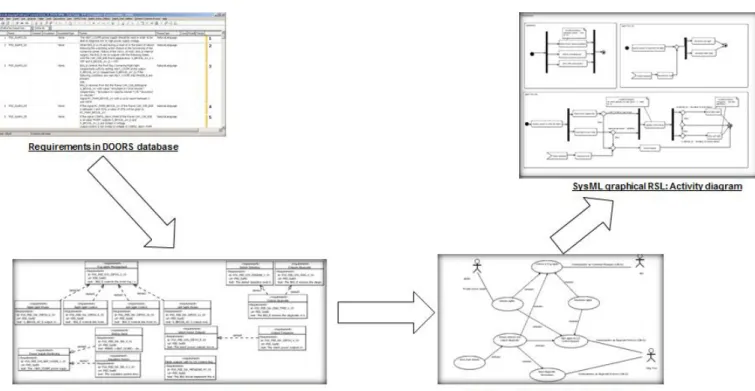
– Our Requirement-to-Design Change Impact Analysis (RD-CIA) solution, marked (5) in Figure 1.1, focuses on propagating changes from NL requirements to system designs, when

(Note that in terms of features coverage Blackboard [ 5 ] is closely related to Moodle, but we could not survey it because of not being able to access to a demo license. Anyhow,

Distributed under a Creative Commons Attribution| 4.0 International License Functional Requirements for a Collaborative Order Management Tool for Use in an Engineering Setting1.

(2) Using four industrial requirements documents, we ex- amine the number of times each of the extraction rules im- plemented by our model extractor is triggered, providing in-

For example, the code send 11.1 identifies five verbs used in the extracted requirements: “return”, “send”, “for- ward”, “pass”, “export” and “import”(Table 4 and Table

To generate executable test cases from misuse case specifications we employ some concepts of natural language programming, a term which refers to approaches automatically