Analysis of Civil Aircraft Propulsors with Boundar
Ingestion
by
David Kenneth Hall
B.S.E., Duke University (2008)
S.M., Massachusetts Institute of Technology (2011)
y Layer ARCHIVES
MASSACHUSETTS INSTITUTE
OF TECHNOLOLGY
MAR 09 2015
LIBRARIES
Submitted to. the Department of Aeronautics and Astronautics
in partial fulfillment of the requirements for the degree of
Doctor of Philosophy in Aeronautics and Astronautics
at the
MASSACHUSETTS INSTITUTE OF TECHNOLOGY
February 2015
@
Massachusetts Institute of Technology 2015. All rights reserved.
Signature redacted
A uthor ... ,.... ...
.-
--
.
.
--.
----.
Department of Aeronautics and Astronautics
January 14, 2015
Certified by..
Certified by..
iqnature redactecd
. .... ... I...Edward M. Greitzer
ff7
H.N. Slater Professor of Aeronautics and Astronautics
Signature redacted'
Thesis Committee Chair
Signature redacted
Certified by...
Certified by...
Si
Accepted by ...
...
Choon Sooi Tan
Senior Research Engineer
Thesis Committee
...
Mark Drela
i
A
'4w'y J. Kohler Jrofessor of Fluid Dynamics
Signature
redacted
Thesis Committee
...
Nicholas A. Cumpsty
Professor Emeritus, Imperial College
gnature redacted
Thesis
Committee
...
Paulo Lozano
Associate Professor of Aeronautics and Astronautics
Graduate Committee Chair
Analysis of Civil Aircraft Propulsors with Boundary Layer Ingestion
by
David Kenneth Hall
Submitted to the Department of Aeronautics and Astronautics on January 14, 2015, in partial fulfillment of the
requirements for the degree of
Doctor of Philosophy in Aeronautics and Astronautics
Abstract
This thesis describes (i) guidelines for propulsor sizing, and (ii) strategies for fan turbo-machinery conceptual design, for a boundary layer ingesting (BLI) propulsion system for advanced civil transport aircraft. For the former, configuration performance analysis shows BLI yields a reduction in mechanical power required to propel a given aircraft. For the latter, fan turbomachinery design attributes are identified to mitigate the impact of BLI inlet distortion on propulsor performance.
The propulsion system requirements are determined using a mechanical energy analy-sis, in which the performance of the airframe and propulsor are characterized in terms of sources and sinks of power. Using this framework, the propulsor can be sized based on the performance of the isolated airframe. Analysis of the power savings due to BLI (from reduction of viscous dissipation both in the aircraft wake and the propulsor jet) leads to scaling choices for the sizing of propulsor simulators for wind tunnel experiments to assess BLI benefit.
Fan stage distortion response is assessed computationally for a range of turbomachinery design parameters and for distortions characteristic of BLI. The numerical results show the importance of three-dimensional flow redistribution upstream of the fan, and indicate that, for the parameters examined, non-axisymmetric fan stators have the largest effect on decreasing blade row velocity distortions and thus mitigating losses due to flow non-uniformity.
Thesis Committee Chair: Edward M. Greitzer
Title: H.N. Slater Professor of Aeronautics and Astronautics Thesis Committee: Choon Sooi Tan
Title: Senior Research Engineer Thesis Committee: Mark Drela
Title: Terry J. Kohler Professor of Fluid Dynamics Thesis Committee: Nicholas A. Cumpsty
Acknowledgments
There are many people to acknowledge for their contributions to the work that ultimately resulted in this thesis. First, I'd like to thank my advisors, Professor Ed Greitzer and Dr. Choon Tan. Their guidance, both in technical matters and in how to conduct effective research, has been nothing short of excellent. Working with them has been a pleasure, and I look forward to continuing to do so in the future. The guidance of Professor Mark Drela and Professor Nick Cumpsty also deserves special recognition; although my interactions with them were less frequent than with the other half of my thesis committee, their technical insight and advice over the years has been no less valuable. I'd also like to thank Professor Zoltan Spakovsky and Dr. Alejandra Uranga for serving as readers on my thesis defense committee and for their helpful comments on drafts of this thesis.
This research was carried out as part of the NASA Fixed Wing Project under Coopera-tive Agreement NNX11AB35A. I gratefully acknowledge the financial support of the NASA Fundamental Aeronautics Program, as well as the use of the NASA R4 fan geometry used in Chapter 5.
My work benefited from technical discussions with various experts in the field outside of
MIT. In particular, I'd like to mention Alan Epstein, Wes Lord, and Jayant Sabnis of Pratt
& Whitney, Greg Tillman of United Technologies Research Center, and John Adamczyk,
Randy Chriss, and Michael Hathaway of NASA.
I'm thankful to have been able to participate in such an ambitious and exciting research endeavor. The success of the project is a testament to the hard work and professionalism of the MIT N+3 team members: Cecile Casses, Alex Espitia, Adam Grasch, Arthur Huang, Michael Lieu, Dr. Sho Sato, Nina Siu, Dr. Neil Titchener, Dr. Alejandra Uranga, and Elise van Dam. It has been a joy working with all of them.
For the last six years, the Gas Turbine Lab has been something of a second home for me, and there are many members of the GTL who have helped along the way. First, I'd like to thank the members of "Team Body Force," Max Brand, Dr. Jeff Defoe, Anjaney Kottapalli, Dr. Claudio Lettieri, Dr. Andreas Peters, and Will Sorensen, each of whom at some point provided assistance in understanding and implementing the source term (or "body force") method described in Chapter 5. Second, I'd like to thank my fellow GTL network administrators, Jeff Defoe, Andreas Peters, David Clifton, and Andras Kiss; special
thanks also to Professor Spakovszky for giving me the opportunity to give something back to the lab while learning a useful new skill by serving in this capacity. Third, I'd like to mention the other (former) PhD candidates who at one point occupied desks in 31-259, Dr. Jon Everitt, Dr. Andreas Peters, and Dr. Sho Sato (the other member of "Team Power Balance"), for daily interactions both technical and non-technical. I'd also like to thank Robin Courchesne-Sato, without whom work at the GTL would certainly grind to a halt.
Finally, I'd like to thank my friends and family for keeping me going as I pursued my degree. I've made many great friends during my time in Cambridge, and I'd like to specifially mention Leah, Juan, Bill, Ronan, Katie, Sarah, Rob, and Kevin for their friendship over the years. Last but not least I'd like to thank my family, both here in Massachusetts and from back home in North Carolina, especially Papa, Christine, Mom, and Dad, for their constant love and support.
Contents
1 Introduction 1.1 Approach . . . . 1.2 Contributions . . . . 1.3 Thesis Outline . . . . 2 Background2.1 BLI Aircraft Performance . . . . 2.1.1 Commerical Aircraft Concepts . . 2.1.2 Aircraft Performance Analysis with 2.2 Turbomachinery Distortion Response . . .
2.2.1 Previous Modeling Approaches . . 2.2.2 BLI Fan Distortion Response . . .
the
3 BLI Configuration Performance Analysis 3.1 Mechanical Energy Analysis . . . .
3.1.1 Propulsive Power Requirement . . . 3.1.2 Propulsive Efficiency . . . .
3.1.3 Power Saving Coefficient . . . .
3.2 BLI Aircraft Configuration Performance . .
3.2.1 Propulsive Power Requirement . . . 3.2.2 Selection of Propulsive Efficiency . .
3.2.3 Scaling for Experimental Assessment
3.3 BLI Propulsor Performance . . . .
3.3.1 Fan Pressure Rise . . . . 3.3.2 Impact of Fan Efficiency on BLI Fuel 3.4 Summary . . . . Power of BLI Balance Benefit Burn Benefit
4 Two-Dimensional Circumferential Distortion Analysis
4.1 Flow Description . . . . 4.2 Circumferential Distortion Response . . . .
4.2.1 Flow Field Behavior . . . .
Method 21 22 23 25 27 27 28 28 32 32 35 37 37 38 40 43 43 44 46 47 50 50 53 57 59 59 62 63
.
4.2.2 Blade Row Performance . . . . 63
4.3 Sensitivity of Performance to Design Parameters . . . . 65
4.3.1 Design Point Loading and Flow Coefficient . . . . 65
4.3.2 Distortion-Component Interactions with Axisymmetric Installation 66 4.3.3 Non-Axisymmetric Geometry and Flowpath Effects . . . . 68
4.3.4 D iscussion . . . . 71
4.4 Sum m ary . . . . 73
5 Three-Dimensional Fan Stage Distortion Response Analysis 75 5.1 Turbomachinery Source Term Model . . . . 75
5.1.1 Approximate Flow Description . . . . 76
5.1.2 Governing Equations . . . . 78
5.2 Blade Camber Surface Loading Model . . . . 79
5.3 Assessment of the Source Distribution Representation . . . . 81
5.3.1 Two-Dimensional Cascades with Uniform Inlet Conditions . . . . 81
5.3.2 NASA R4 Fan Stage . . . . 82
5.4 Sum m ary . . . . 90
6 Distortion Tolerant Propulsor Design Attributes 93 6.1 Parametric Geometry Description . . . . 93
6.2 Fan Stage Design Assessment . . . . 94
6.2.1 Stage Design Point and Radial Loading Distribution . . . . 95
6.2.2 Rotor-Stator Interaction . . . . 99
6.2.3 Non-Axisymmetric Stator Geometry . . . . 100
6.3 D iscussion . . . . 101
7 Summary, Conclusions, and Recommendations 105 7.1 Summary and Conclusions . . . . 105
7.2 Recommendations for Future Work . . . . 106
A Two-Dimensional Linearized Flow Distortion Analysis 109 A.1 Equations of Motion . . . . 109
List of Figures
1-1 Boundary layer ingestion reduces wasted energy both in the wake of the airframe being propelled and in the jet downstream of the propulsor (adapted
from D rela [1]) . . . . 21
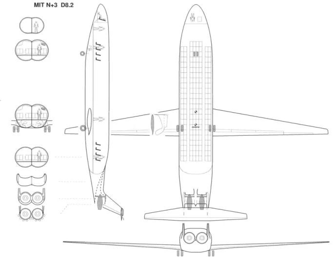
2-1 The MIT D8 aircraft configuration: a 180 passenger civil aircraft concept for reduced environmental impact. . . . . 29
2-2 Sources of dissipation, <b, can be estimated based on conventional drag and boundary layer quantities, and are insensitive to perturbation pressure field effects for integrated configurations. . . . . 31 2-3 Parallel compressor model for circumferential distortion response (adapted
from Longley and Greitzer [19]); average performance with inlet distortion is estimated assuming parallel streams operating on uniform flow characteristics. 33 2-4 Axial velocity distortion attenuation leads to circumferential flow
redistri-bution and inlet flow angle variation at compressor location (adapted from
Longley and Greitzer [19]). . . . . 34
3-1 BLI body-propulsor configuration with dissipation sources used in lumped parameter mechanical energy analysis. . . . . 38 3-2 Non-dimensional propulsor flow power PK/(VoD') versus non-dimensional
propulsor mass flow rhVo/D' for different values of BLI fraction fBLI; in-creasing BLI fraction at fixed propulsor mass flow decreases mechanical flow pow er. . . . . 41
3-3 Propulsive efficiency 77, versus non-dimensional propulsor mass flow rmVo/D' for different values of BLI fraction fBL,; increasing BLI fraction at fixed propulsor mass flow increases propulsive efficiency, approaching unity as the entire wake is ingested. . . . . 42 3-4 Non-dimensional propulsor input power PK/(VoD') versus propulsive
effi-ciency 77p for different values of BLI fraction fBLI; increasing BLI fraction yields smaller flow power reduction at fixed propulsive efficiency than at fixed mass flow . . . .. . . . . 44
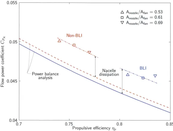
3-5 D8 flow power coefficient CPK versus propulsive efficiency qp in BLI and non-BLI configurations; symbols show TASOPT-optimized configurations, and dashed curves are estimates based on the optimized BLI D8 airframe performance using the lumped parameter mechanical energy analysis. . . . 46
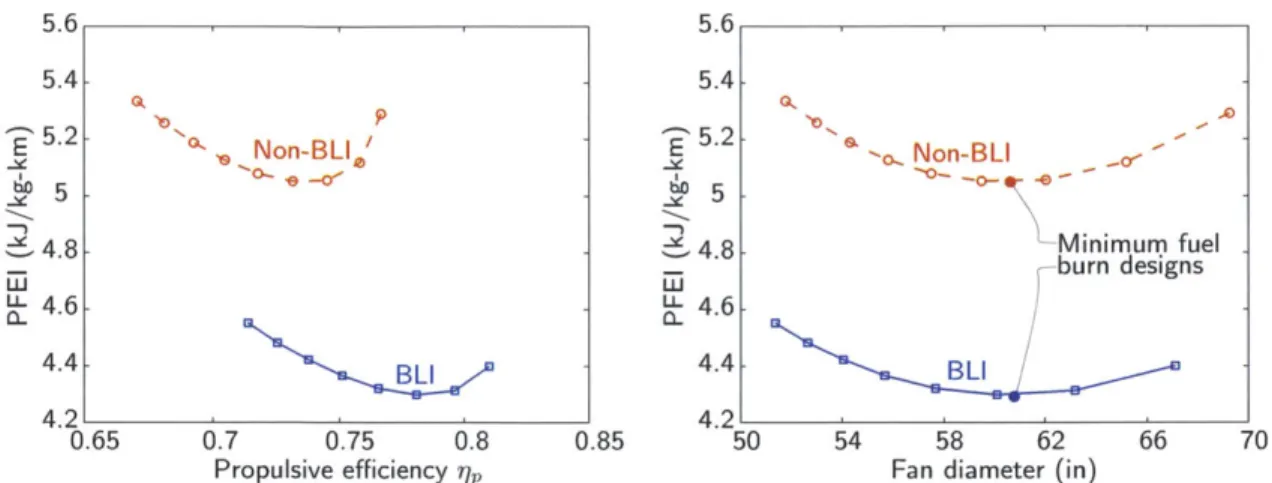
3-6 Payload Fuel Energy Intensity versus propulsive efficiency (left) and fan
di-ameter (right) for TASOPT-optimized BLI and non-BLI D8 configurations; minimum fuel burn BLI design has higher propulsive efficiency than non-BLI design at approximately equal fan diameter. . . . . 47
3-7 D8 wind tunnel model flow power coefficient CpK vs propulsive efficiency
ij,; experimental measurements (symbols) [34] differ from lumped
parame-ter mechanical energy analysis (solid and dashed curves) by approximately constant offset attrubted to propulsion system dissipation. . . . . 49
3-8 Propulsive efficiency versus propulsor stagnation pressure rise coefficient Apt/qoo
for body-propulsor configurations with different values of BLI fraction fBLI; increasing BLI fraction increases propulsive efficiency for given propulsor stagnation pressure rise due to reduced inlet mechanical energy flux and jet velocity. . . . . 51 3-9 Propulsive efficiency versus fan pressure ratio for TASOPT-optimized D8
BLI and non-BLI configurations; minimum fuel burn BLI design has higher propulsive efficiency and lower FPR than non-BLI design. . . . . 53 3-10 Fuel power saving versus cruise fan efficiency for TASOPT-optimized
config-urations with different assumptions about fan efficiency with BLI; fuel burn increases 0.8% per 1% decrease in cruise fan efficiency. . . . . 54
3-11 Fan maps for case A (top) and C (bottom); contours of fan efficiency
ver-sus corrected mass flow and fan pressure ratio; climb angle at top of climb decreases to accommodate decreases in off-design fan efficiency without ad-versely affecting mission fuel burn. . . . . 56
4-1 Model flow geometry: annular flow path (top left), "unrolled" geometry (top right) with axial and circumferential variations in passage height, and two-dimensional computational domain with rotor and stator actuator disks (bot-tom).. ... . . .. .. .. ... . ... 60
4-2 Circumferential distributions of perturbation stagnation pressure (top left), static pressure (top right), axial velocity (bottom left), and circumferential velocity (bottom right), stagnation pressure, and static pressure, normalized
by the inlet stagnation pressure distortion magnitude; the analysis captures
upstream axial velocity distortion attenuation, swirl generation, and rotor distortion transfer. . . . . 64 4-3 Circumferential distributions of inlet flow angle perturbations for rotor (left)
and stator (right) . . . . 65
4-4 Two-dimensional stage (#, P) design points (symbols), stagnation enthalpy
rise characteristics (diagonal lines), and constant 0/0 2 propulsive power
re-quirement (gray parabola). . . . . 66
4-5 Rotor (left) and stator (right) incidence distortion versus stage flow coefficient
#
and enthalpy rise coefficient 0 for LR-s = 0 and constant flow path area . 674-6 Rotor (left) and stator (right) incidence distortion versus stage flow coefficient
#
and enthalpy rise coefficient 0 for LR-s = 2R and constant flow path area 674-7 Rotor (left) and stator (right) incidence distortion versus axial rotor-stator spacing for representative (#,,0) design points . . . . 68
4-8 Rotor (left) and stator (right) incidence distortion versus downstream nozzle area ratio and axial length;
#
= 0.47, 0 = 0.24, LR-S= 0 . . . . 694-9 Rotor (left) and stator (right) incidence distortion versus stator exit angle perturbation phase relative to the inlet stagnation pressure perturbation, and stator exit angle perturbation phase; h = constant,
#
= 0.47, 0 = 0.24,4-10 Rotor (a) and stator (b) incidence distortion versus nozzle exit height per-turbation phase and magnitude . . . . 71 5-1 Three-dimensional blading geometry represented as a continuous distribution
of momentum and energy source terms within the blade row swept volume. 76 5-2 Comparison of two-dimensional cascade flow to equivalent model flow with
source term distribution . . . .. 77 5-3 Geometric description of local blade camber surface, relative velocity, and
resulting flow-normal momentum source; the blade camber surface normal n^, the relative velocity W, and the momentum source
f
all lie on the common two-dimensional plane shown on the right . . . . 80 5-4 Calculated cascade static pressure rise vs incidence for geometriesrepresen-tative of fan stage rotor and stator blade sections, MISES versus source term analysis . . . . 82 5-5 NASA R4 fan stage meridional flow path geometry and boundary conditions 83 5-6 NASA R4 rotor stagnation enthalpy rise characteristic; RANS computations
vs axisymmetric source term model with uniform inlet conditions . . . . 84 5-7 NASA R4 rotor radial stagnation enthalpy rise distribution; RANS
compu-tations vs axisymmetric source term model . . . . 85 5-8 BLI inlet stagnation pressure distribution . . . . 85 5-9 Rotor inlet non-dimensional stagnation pressure (pti - ptOO)/(p(Qrtip)2) . . 86 5-10 Rotor incidence angle distortion 01 - . . . . 86 5-11 Rotor stagnation enthalpy rise coefficient
4
= Aht/(Qrtip)2 . . . . 87 5-12 Rotor streamtube area contraction ratio (p2u2)/(plUl) . . ... . . 87-0
5-13 Rotor velocity ratio distortion W1/W2 - (W1/W2) . . . . . .. . 88
5-14 Rotor diffusion factor distortion DF - DF . . . . 88 5-15 Stator inlet non-dimensional stagnation pressure (Pt3 - Ptoo)/(p(rtip)2) . . 89 5-16 Stator incidence angle distortion a3 - .a . .. . . . . . . . . . . . . .. . 90 5-17 Stator velocity ratio distortion V3/V4 - (V3/V4). - -- ---... 91
5-18 Stator diffusion factor distortion DF - DF. . . . . 91 6-1 Fan stage meridional geometry for inlet distortion response parametric design
study calculations . . . . . . . . 94
6-2 Design point enthalpy rise and flow coefficient; all point have the same design point ?p/#2 (thrust requirement), three designs have different radial loading distributions at constant overall
#
and 0 . . . . . 95 6-3 Design point radial stagnation enthalpy rise distributions; the geometrieswith different overall design point (#, 0) have approximately uniform loading
distributions. . . . . 96
6-4 Changes in rotor inlet absolute swirl angle with changes in stage design point and radial loading distribution; increases in overall stagnation enthalpy rise lead to decreased characteristic slope, weaker upstream redistribution, and reduced incoming swirl. . . . . 97 6-5 Changes in rotor and stator velocity ratio distortion with changes in stage
design point; rotor hub and midspan distortions dominated by incoming swirl distortion, which increases with decrease loading; rotor tip section and stator sections behave in accord with two-dimensional analysis. . . . . 98 6-6 Changes in rotor and stator velocity ratio distortion with changes in radial
loading distribution; behavior is similar to two-dimensional analysis because the upstream redistribution is insensitive to changes in the radial loading distribution at fixed
#
and#.
. . . . 98 6-7 Fan stage meridional geometry with closely spaced, baseline, and fardown-stream stator locations . . . . 99 6-8 Changes in rotor and stator velocity ratio distortion with changes in
rotor-stator axial spacing; behavior is similar to two-dimensional analysis. .... 99 6-9 Comparison of rotor incidence (left) and velocity ratio (right) distortions for
non-axisymmetric stator geometries; stator exit perturbation angle 6o4 = 100
can reduce incidence distortion depending on phase, but amplifies velocity ratio distortion in all cases. . . . . 101 6-10 Rotor tip (left) and hub (right) velocity ratio distortions for various
non-axisymmetric stator geometries; distortion reduction is achieved by scaling stator exit angle based on axisymmetric and non-axisymmetric results as-suming linear relation between velocity ratio and exit flow angle variations. 101
List of Tables
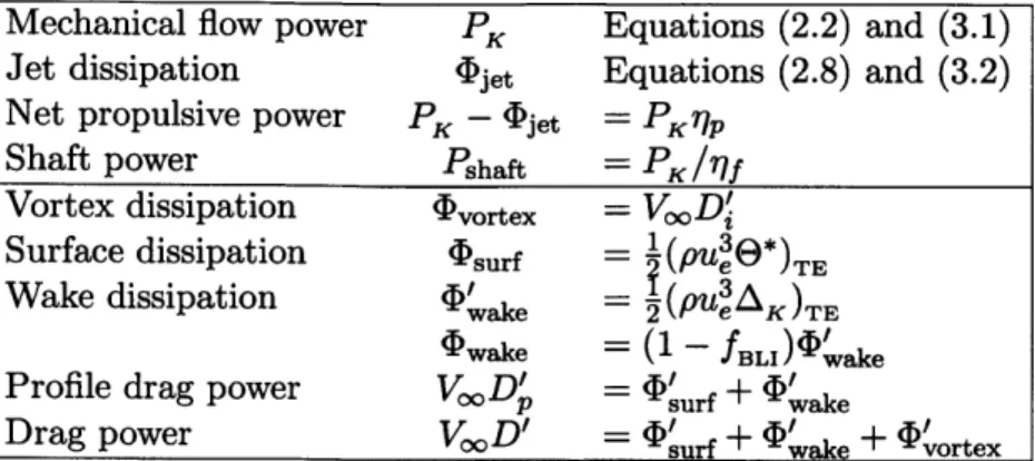
3.1 Definition of power and dissipation terms used in lumped parameter mechan-ical energy analysis. . . . . 39 3.2 Fan design parameters and resulting configuration performance for various
Nomenclature
Ajet propulsor jet area
AR blade aspect ratio
B number of blades/vanes
c chord
CD drag coefficient (= D/(jpoVSref))
CPK mechanical flow power coefficient (= PK/(IPoVSref))
Cx net streamwise force coeffient (= X/(jpoV Sref))
C,> dissipation coefficient (= <b/(PooVSref))
D drag force
Di induced drag DF diffusion factor dfan fan diameter
C mechanical energy deposition rate energy source term
F thrust force
f momentum source term
fe
flow-parallel momentum sourcef, flow-normal momentum source
fBLI boundary layer ingestion fraction
H circumferential average annulus height
H* boundary layer kinetic energy shape factor ( 9*/9)
h annulus height
ht stagnation enthalpy
kC mechanical energy flux
rh propulsor mass flow rate
rmcorr corrected mass flow (= rh Tt/Tref/(Pt/Pref)) Neng number of engines or propulsors
n blade camber surface normal
P circumferential average static pressure
Pt circumferential average stagnation pressure
PK mechanical flow power
p static pressure
Pt stagnation pressure
q dynamic pressure (=
jpV
2)R annulus mean radius
r radius
S area
T static temperature
Tt stagnation temperature Utip fan tip speed (= Qrtip)
U, V circumferential average axial, tangential velocities (Ch. 4)
u, v, w Cartesian velocity components
Ue boundary layer edge velocity
V velocity vector
V velocity magnitude
W rotor relative velocity vector
W rotor relative velocity magnitude
X net streamwise force
x, y, z Cartesian coordinates (x axial, y = RO circumferential in Ch. 4)
x, r, 0 cylindrical coordinates
a absolute flow angle
0 reduced frequency, rotor-relative flow angle
ACprop additional dissipation coefficient attributed to propulsor integration
6 boundary layer thickness
6K boundary layer kinetic energy excess thickness
'r, propulsive efficiency
9 boundary layer momentum thickness (Ch. 3), circumferential coordinate (Ch. 4-6)
9* boundary layer kinetic energy thickness
A local flow deviation angle ( blade stagger angle
p density
<P dissipation
#5
flow coefficient (= V/(Qrtip))/ stagnation enthalpy rise coefficient (= Aht/(Qrtip )2)
O/)TT total pressure rise coefficient (= Apt/(p(Qrtip)2))
Q rotor rotation rate
Acronyms
BLI boundary layer ingestion FPR fan pressure ratio
PFEI payload fuel energy intensity
PSC power savings coefficient
Subscripts
fuse fuselage inl propulsor inlet out propulsor outlet surf surface
TE trailing edge x axial component
oo free stream
Superscripts
' non-BLI quantity (Ch. 3), perturbation quantity (Ch. 4) circumferential average
Chapter 1
Introduction
The concept of boundary layer ingestion (BLI) is illustrated in Figure 1-1. For conventional propulsion without BLI, the airframe drag, equal to the momentum deficit in the down-stream wake, must be balanced by the engine thrust, equal to the excess momentum in the propulsor jet. The excess kinetic energy in both wake and jet are lost as viscous dissipation, resulting in additions to the propulsive power needed to produce the thrust. With BLI, a portion of the airframe boundary layer is passed through the propulsor, reducing the wake momentum deficit and jet kinetic energy. The condition of zero net momentum downstream is thus achieved with a reduction in wasted kinetic energy in the combined wake and jet
flow, leading to decreased propulsive power and, ultimately, fuel burn.
A number of challenges exist in design and analysis of BLI aircraft configurations and
their propulsion systems. One is that the definition of the propulsion system requirements becomes more difficult because the concepts of thrust and drag become ambiguous with
Zero Net Wasted
Momentum Kinetic Energy
airframe wake +
4- _propulsor jet +
- I
- + combined -wake and jetFigure 1-1: Boundary layer ingestion reduces wasted energy both in the wake of the airframe being propelled and in the jet downstream of the propulsor (adapted from Drela [1])
a tightly integrated propulsion system. The disturbance pressure field of the propulsor will alter the surface forces on the airframe, so the engine thrust requirement cannot be determined based on the drag of the isolated airframe. A second effect is that the ingested boundary layer flow enters the propulsor at reduced momentum flux, relative to free stream stagnation conditions typically seen at the engine inlet. Both these effects modify the power that needs to be added to the flow by the propulsor in order to maintain zero net force on the aircraft at the cruise condition.
A second challenge with BLI is that part of the benefit can be offset by decreased engine
performance, particularly that of the bypass fan stage, which may be adversly affected by the presence of inlet distortion. The spatial non-uniformity in flow conditions across the height of the boundary layer presents non-uniform and unsteady conditions to the fan as it rotates through the boundary layer, so that part of the fan is always operating at "off-design" conditions with reduced efficiency.
The objective of this thesis is to address these two challenges at the conceptual design level. We propose a methodology for characterizing the propulsion system requirements in terms of flow mechanical energy, eliminating the difficulties of momentum-based accounting, and providing a procedure for engine sizing based on the performance of an isolated airframe. We also examine the sensitivity of blade row performance with inlet distortion to changes in various propulsor design parameters, to determine attributes of fan stage design and installation that mitigate the adverse effect of BLI on engine performance. The analyses in this thesis can thus serve as a reference early in the design process of fan stages for new BLI applications.
1.1
Approach
The propulsion system requirements are determined using the power balance method of Drela [2]. Rather than considering the forces on the aircraft, the performance of the airframe and engine are characterized in terms of sources and sinks of mechanical energy. Energy related quantities analagous to thrust, drag, and propulsive efficiency are defined, and it is shown that the BLI benefit can be explained as the combined effect of a decrease in effective airframe drag and an increase in propulsive efficiency; for the cases considered here, the latter is the dominant effect. The impact of propulsion system sizing and fan
efficiency on BLI aircraft fuel burn are assessed using the TASOPT aircraft configuration optimization tool [3].
Viewing the system performance in terms of mechanical energy also provides insight into appropriate propulsion system scaling for powered wind tunnel models and for comparison between integrated and conventional podded propulsion system configurations. In this context, complementary experiments have been carried out using powered wind tunnel models with propulsor simulators sized according to the scaling rules presented in this
thesis [4].
The impact of BLI inlet distortion on fan stage turbomachinery performance is assessed using two internal flow analyses. First, a linearized description is introduced and applied to quasi-two-dimensional (x, 0) flow simulating a fan stage to assess the sensitivity of blade row performance to changes in the turbomachinery design and installation. Second, a three-dimensional non-axisymmetric throughflow analysis is developed and applied to different fan stage geometries to assess the effectiveness of strategies for distortion tolerance arising from the two-dimensional description.
For both the external and internal flow analysis, we consider only the performance at the cruise design point. The majority of aircraft fuel burn occurs at cruise, and the viability of BLI should be confirmed at the propulsor design point before considering any off-design analysis. We limit ourselves to incompressible flow. Neglecting the effect of compressibility in the subsonic external flow may change numerical results by a few percent, but trends with the design variables should not be affected [3]. Similarly for internal flow, the relevant flow mechanisms that drive fan stage performance with inlet distortion have been shown to be insensitive to Mach number [5].
1.2
Contributions
1. BLI fuel burn benefit is shown to be enabled by increased propulsive efficiency for a
given fan size. The power requirements of BLI configurations are quantified in terms of (i) the performance of the airframe to be propelled and (ii) the sizing of the propulsor, using the power balance method. Optimization of BLI and non-BLI configurations shows minimum fuel burn occurs in both configurations at approximately equal engine mass flow, with a reduction in required propulsive power in the BLI configuration due
to a reduction in viscous dissipation in the propulsor jet and airframe wake. The former is by far the dominant feature of the configuration examined.
2. Scaling for powered wind tunnel models used to experimentally assess BLI benefit has been defined based on analysis of power savings with BLI. Experimental results show power savings consistent with mechanical energy analysis of the wind tunnel models, confirming the BLI benefit and validating the power balance analysis for
highly integrated aircraft configurations.
3. The impact of changes in fan efficiency on BLI fuel burn benefit has been evaluated for
a proposed BLI aircraft configuration. Changes in fan efficiency are shown to have a small effect on overall BLI fuel burn benefit (less than 1% increase in fuel burn per 1% decreases in fan efficiency). Futher, they do not impact the optimal propulsor sizing. The sizing analysis (external flow problem) and fan performance analysis (internal flow problem) can thus each be carried out independently.
4. An analysis for simulating fan performance with three-dimensional inlet distortions has been developed. The flow through the fan blading is modeled using steady dis-tributed momentum and energy sources on an axisymmetric grid. The source distribu-tions are determined as a function of specified blade geometry. The formulation allows approximate calculation of non-axisymmetric flow fields that capture the relevant flow redistribution and distortion transfer at a reduced computational cost compared to full-wheel unsteady calculations, and without any a priori flow or performance data.
5. Flow mechanisms that determine conditions at the blade rows in fan stages with BLI
are identified. The analysis shows that three-dimensional upstream flow redistribution results in rotor inlet conditions not predicted by two-dimensional compressor distor-tion response analysis. The rotor distordistor-tion transfer, downstream flow behavior, and rotor-stator interactions, however, are captured well by a linearized two-dimensional analysis.
6. Fan stage turbomachinery design attributes that can potentially mitigate the impact of
BLI inlet distortion on propulsor performance are identified. It is found that effective non-axisymmetric stator design can (i) reduce velocity distortions and thus mitigate losses in the rotor and (ii) reduce losses in the stator by tailoring the geometry to
accept the incoming distortion downstream of the rotor.
1.3
Thesis Outline
Background on BLI and turbomachinery distortion response, including a review of the rele-vant literature, is provided in Chapter 2. Chapter 3 presents an analysis of BLI benefit and propulsor sizing, including the impact of reduced fan efficiency due to inlet distortion. Chap-ter 4 contains a linearized actuator disk distortion response analysis for two-dimensional fan stage blade-to-blade flows, which is used to identify design attributes that have the potent to mitigate the impact of inlet distortion on propulsor performance. Chapter 5 contains a description of an approximate analysis for turbomachines, which is used in Chapter 6 to assess the impact of various changes in fan stage design on performance with BLI inlet distortion. Conclusions and recommendations for future work are given in Chapter 7.
Chapter 2
Background
This chapter provides an overview of previous work related to aircraft propulsion with BLI. The chapter is divided into two broad categories, BLI aircraft performance and turboma-chinery distortion response. A survey of the relevant literature is given on these topics, including a description of the power balance methodology used in Chapter 3, an overview of compressor distortion response modeling methodologies, and results from recent work on fan stages with BLI-type inlet distortions.
2.1
BLI Aircraft Performance
The concept of boundary layer ingestion as a way to reduce required propulsive power has been understood for some time. In marine applications, the location of a ship's propeller close to the trailing edge of the hull makes BLI inevitable. For design, the effect of BLI has typically been considered as an increase in propulsive efficiency for a required thrust [6] [7]. Betz [8] accounts for BLI benefit in this way, but provides a conceptual description of the benefit of re-energizing part of the wake of a body.
Smith [9] presents BLI as a means of increasing the efficiency of aircraft propulsors. The BLI benefit is quantified in terms of propulsive efficiency, defined as the product of free stream velocity and the drag of the propelled body (i.e., the drag power of the body) divided by the power added to the flow by the propulsor. This definition captures the beneficial effect of BLI, since the power added decreases with BLI, but it neglects that the force on the body will change due to the pressure field of an integrated propulsor.* Smith
acknowl-also defines a power-saving coefficient, used to compare the performance of BLI and non-BLI configurations. The analysis presented in Chapter 3 proceeds in a manner similar to Smith, but uses a framework based on mechanical energy analysis.
2.1.1 Commerical Aircraft Concepts
In recent years, commercial aircraft concepts using BLI have been proposed. The work of the Cambridge-MIT Silent Aircraft Initiative (SAI) resulted in a hybrid wing-body aircraft concept optimized for low noise [10] [11]. The design included an embedded propulsion system to reduce noise and increase propulsive efficiency by ingesting a portion of the fuselage boundary layer [12] [13]. Similar designs have been analyzed by NASA for their potential for reduced environmental impact [14]. Most notably, one of these designs [15] has been selected as the platform for the detailed design of a propulsor to be used in a high speed fan rig test to assess fan stage performance with BLI inlet distortion.
The configuration of interest in this thesis is the MIT D8, which was developed as part of a NASA funded program to identify aircraft concepts and technologies for reduced en-vironmental impact [16]. A schematic of the design is shown in Figure 2-1. Key design features include reduced cruise Mach number which allows reduction in wing sweep, weight, and drag, a "double-bubble" fuselage design which provides extra carry-over lift, and an empenage configuration featuring two vertical tails and flush-mounted engines that ingest a portion of the fuselage boundary layer. The reduced Mach number and fuselage-engine integration with short inlets leads to BLI inlet distortions with little or no streamwise vor-ticity, unlike previous designs with long S-duct inlets upstream of the fan [17]. In Chapters
5 and 6 we therefore consider the effects on the fan stage of vertically stratified stagnation
pressure distributions far upstream.
2.1.2 Aircraft Performance Analysis with the Power Balance Method
In Chapter 3, the propulsion system requirements with BLI are determined using the Power
Balance Method developed by Drela [2]. Because the propulsor pressure field will alter the surface forces on the airframe, and the ingestion of the airframe boundary layer changes the inlet conditions of the propulsor, airframe drag and engine thrust are not easily defined for
edges this fact, and his definitions for thrust and drag -while not representing specific forces that could be measured in a body-propulsor configuration - provide a consistent framework for evaluating BLI benefit.
MIT N+3 D8.2
CD>
FCur -1:, Th MI D8-
airraf cLfgrain a 8 asne ii arrf ocp
LIT -1
C-Figure 2-1: The MIT D8 aircraft configuration: a 180 passenger civil aircraft concept for
reduced environmental impact.
BLI configurations. It is more useful, therefore, to work in terms of power than in terms
of forces, and the power balance method considers the mechanical flow power quantities.
For level unaccelerated flight, the power added to the propulsor mass flow must balance the viscous dissipation or lost power in the flow around the aircraft,
PK CV' (2.1)
where PK is the power added to the flow, defined as the rise in mechanical energy flux from the inlet to the exit of a propulsor,
K
K
+ (V22 hdSprop,
and PCV is the viscous dissipation in the flow, integrated over a control volume extending far from the aircraft in all directions,
aGV
=
(JJ
-
V)-
VdV.
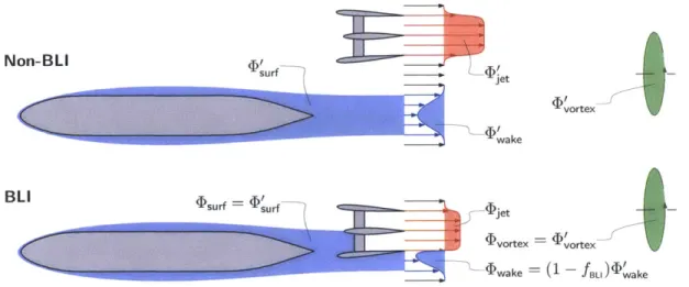
(2.3)Typically, the volume integral in Equation (2.3) is not calculated directly. The dissi-pation is confined to viscous boundary layers, wakes, and the trailing vortex system down-stream of an aircraft. These dissipation sources are illustrated schematically in Figure 2-2. For non-BLI configurations (denoted by primed ()' quantities), the dissipation sources of the isolated airframe can be characterized in terms of conventional drag metrics and the state of the boundary layer at various locations. The vortex dissipation, 4vortex, is defined as the excess mechanical energy in the vortex system downstream of the aircraft, which is equal to the induced drag power,
Vvortex =
VooD
.The surface dissipation, 'urf, is the power lost in the boundary layer on solid surfaces, and is equal to the boundary layer kinetic energy defect at the trailing edge of the airframe, which is related to the boundary layer kinetic energy area E*,
surf = (pujE*) = (2.4)
The wake dissipation, VGake, is the excess mechanical energy of the wake in the reference frame of a stationary observer, and is related to the wake kinetic energy excess area AK at the trailing edge of the airframe,
wake =
2(PUeAK)T.
= JJ(Ue - u)2pudSTE. (2.5)
The sum of the surface and wake dissipation is equal to the profile drag power, VO0D', which
is characterized by the momentum defect in the wake,
D surf
+
wake = (pu!e)wake = UeJJ(Ue
- u)pu dSwake, (2.6) where the boundary layer momentum areaE
is evaluated at a location far downstream atNon-BLIV surf --- "D et a vortex
~wake
BLI D (Dvortex ~^ vortex AIwake ~ (1 fBl)akeFigure 2-2: Sources of dissipation, D, can be estimated based on conventional drag and boundary layer quantities, and are insensitive to perturbation pressure field effects for in-tegrated configurations.
free stream static pressure. The relative contributions of surface and wake dissipation to total profile drag depend on the state of the boundary layer at the trailing edge of the body. Combining Equations (2.4) and (2.6) yields the surface dissipation contribution in terms of the boundary layer kinetic energy shape factor H* = 0*/E,
V
~H*
surf = VooD' TE (2.7)
For attached turbulent flow, H* ~ 1.75 [2], and the surface and wake dissipation account for approximately 7/8 and 1/8 of the drag power, respectively.
The jet dissipation, (jet, is the excess mechanical energy of the propulsor jet,
4)jet = J(Vo - Vjet)2P~jet dSout. (2.8)
In Chapter 3, we show that the jet dissipation will depend on the propulsive power require-ment of the configuration, the amount of boundary layer ingested, and the selection of the propulsor mass flow. 2-2.
With BLI, the dissipation is altered because of the re-energizing of the ingested wake, as in Figure 2-2. As suggested by Drela [2][3], and shown computationally for a range of body-propulsor configurations by Sato [181, a quantitatively useful approximation is that
the vortex and surface dissipation are unaffected by the presence of the propulsor,t
'Dvortex = vortex, (2.9)
4surf = 'surf- (2.10)
The wake dissipation, however, is reduced by an amount equal to the downstream dissipation would occur in the fraction fBLI of the boundary layer flow ingested by the propulsor,
Dwake = (1 - fBLI) wake* (2.11)
In Chapter 3, an analysis of Equations (2.1)-(2.11) is carried out to show the physical mechanisms of BLI benefit. Using this framework, it is easy to show that BLI reduces the required flow power PK due to reduced wake dissipation (see Equation (2.11)) and jet dissipation, depending on the sizing of the propulsor.
2.2
Turbomachinery Distortion Response
The response of fans to steady inlet distortion has also received attention. Earlier work on compression system modelling identified distortion-component coupling effects in the case of two-dimensional circumferential distortions, with the main concern being the impact of distortion on stall margin. Although the application and objectives are different, many of the basic principles are applicable to our study of design point BLI fan efficiency. More recent analyses have been used for fan stage distortion response analysis. These methods, along with results from higher-fidelity assessments of fan stages with BLI-type inlet distortions, form a basis for the fan stage distortion analysis in this thesis.
2.2.1 Previous Modeling Approaches
Longley and Greitzer [19] provide an excellent review of considerations for propulsion system inlet distortion response, and we present two important concepts here. First, we consider
parallel compressor theory, in which a non-uniform flow through a compressor is treated as
two separate one-dimensional flows. The streams operate on different points on the
com-tThis is not true for the force on the body, which can be altered due to the perturbation pressure field of a downstream propulsor.
High stagnation pressure -
A
Loss in- - - Efficiency
*TT
Apt -- - - - -iAV) Loss in
p( )2 -
-- -- --Pressure Rise
Low stagnation Pressure '
Figure 2-3: Parallel compressor model for circumferential distortion response (adapted from Longley and Greitzer [19]); average performance with inlet distortion is estimated assuming parallel streams operating on uniform flow characteristics.
pressor total-to-static pressure rise characteristic as shown in Figure 2-3. If the compressor exit static pressure is assumed constant, the magnitude of the upstream stagnation pressure distortion constrains the total-to-static pressure rise of each stream and thus the difference in flow coefficient and resulting axial velocity distortion. If both the pressure rise charac-teristic and efficiency characcharac-teristic are concave-down (with respect to flow coefficient), the average pressure rise and efficiency are reduced relative to the uniform flow performance.
The parallel compressor model highlights the importance of the slope of the pressure rise characteristic in determining the distortion response. A steeper (more negative) 0,s (0) slope results in lower axial velocity distortion at the compressor, which may also decrease the efficiency reduction, depending on changes in changes in the efficiency characteristic. This suggests one means of improving performance of BLI fan performance, which we assess in Chapters 4 and 6.
A second important concept is the upstream flow redistribution due to interaction
be-tween the distortion and the compressor (or fan). For a two-dimensional flow (representative of high hub-to-tip ratio compressor geometries), the attenuation of axial velocity distor-tion predicted by parallel compressor theory results in the generadistor-tion of non-axisymmetric circumferential velocities (swirl) at the compressor as illustrated in Figure 2-4. The
non-uniformities in axial and circumferential velocity result in flow angle variations at the blade row inlet, creating an off-design incidence range the blades must tolerate. The affect of com-bined axial and circumferential velocity distortions on compressor performance have been
Dividing Streamlines Between Regions of High and Low Axial Velocity
Rotor - - -~{
fRotation
O_ Circumferential Velocity Components at Inlet
Axial Velocity Profile "Unrolled"
Far Upstream 9 Compressor
Figure 2-4: Axial velocity distortion attenuation leads to circumferential flow redistribu-tion and inlet flow angle variaredistribu-tion at compressor locaredistribu-tion (adapted from Longley and Gre-itzer [19]).
assessed using two-dimensional analyses [20]. In Chapter 4, we present such an analysis, based on the work of Greitzer and Griswold [21], with new models for discrete rotor and stator actuator disks and non-axisymmetric stator and flowpath geometries.
In Chapter 5, we develop a non-axisymmetric turbomachinery throughflow analysis for fan stage flows with inlet distortion at a computational cost much lower than those described above. The basic idea is to replace the turbomachinery blade rows with distributions of momentum and energy source terms in the calculation that generate a similar flow field to the actual flow [22] [23]. Similar methods have been used in turbomachinery research at the MIT Gas Turbine Lab to address multistage compressor stability [24], BLI propulsor aerodynamic [25] and acoustic [26] performance, and the design of ultra-short nacelles for low pressure ratio fans [27]. In these previous formulations, the form of the source term dis-tributions is determined by extracting blade forces from single passages RANS calculations carried out over a range of operating conditions and developing a correlation to local flow conditions. In the current implementation, described in Chapter 5, the source terms are determined based on a blade passage description characterized by a specified blade camber surface geometry, eliminating the need for a priori calculations.
2.2.2
BLI Fan Distortion Response
Initial designs of BLI propulsion systems [28] and fan stages [29] did not account for fan efficiency did not asses the impact of BLI inlet distortion on fan efficiency. More recent computational and experimental research carried out on a low speed model of the NASA rotor 67 fan stage has led to useful information on fan response to circumferential inlet distortion [30][31]. A high speed fan stage is also being designed for rig testing with BLI inlet distortion [32], and computations show the fan efficiency decreases by less than 2% relative to uniform inlet conditions.
The recent work of Gunn and Hall [5] provides the most comprehensive treatment of the response of a contemporary fan stage to BLI inlet distortion, and the results of this study are used as a benchmark for assessing the effectiveness of the model presented in Chapter 5. The flow features of BLI fan stage distortion response are identified using unsteady full-wheel
CFD in conjection with experiments on a low speed fan rig. The upstream redistribution
is found to have significant radial components, creating co- and counter-swirl distortions at the fan face along the entire blade span. The distortions result in non-uniform work input affecting the flow into the stator. Fan efficiency was found to decrease by only 1-2% relative to the performance with uniform inlet conditions, with the increased losses concentrated in areas where the local diffusion factor is increased. Computations on a high-speed fan show that while the details of the flow may change, specifically the presence of shocks, the flow features that drive the change in efficiency with distortion are not qualitatively altered by the change in Mach number.
Chapter 3
BLI Configuration Performance
Analysis
First steps in designing a podded (on wing or fuselage) aircraft propulsor include estimating the engine thrust requirements and selecting the physical size of the propulsor. For an aircraft with boundary layer ingestion (BLI), however, the definitions of engine thrust and airframe drag become ambiguous, as described in Chapter 1, and it is more useful to work in terms of power than in terms of forces. We thus define the propulsor requirements using the power balance methodology described in Chapter 2, which allows quantification of the BLI benefit based on sources and sinks of mechanical power in the propulsor and aircraft
flow fields.
A further complication in the assessment and design of BLI propulsors is the effect of
inlet distortion from the ingested boundary layer on propulsor performance. In this chapter, the impact of inlet distortion is considered on a one-dimensional basis, by examining the sensitivity of configuration performance to changes in fan efficiency. Mechanisms leading to increased propulsor losses due to distortion and strategies for distortion tolerant propulsor design are the focus of Chapters 4 through 6.
3.1
Mechanical Energy Analysis
We first examine the impact of BLI for a simple body-propulsor configuration with no vor-tex dissipation as in Figure 3-1. We proceed in a manner aligned with that of Smith [9], characterizing the BLI benefit in terms of propulsive efficiency and power savings, although
Isurf = surf
)jet
-4wake = (1 - fBl)ake
Figure 3-1: BLI body-propulsor configuration with dissipation sources used in lumped pa-rameter mechanical energy analysis.
we make two changes in the analysis. One is that the propulsive power requirement is determined using the power balance method [2]. This results in a definition for propulsive efficiency, based on mechanical power added to the flow by the propulsor and viscous dis-sipation in the external flow, which is different from that of Smith. Second, we cast the analysis in terms of propulsor mass flow as an independent variable upon which the BLI power savings depends.
3.1.1 Propulsive Power Requirement
We adopt a lumped parameter approach, where the airframe performance is characterized in
terms of the dissipation quantities defined in Section 2.1.2, and the propulsor performance is characterized by a mass flow, rh, and jet velocity, Vet. Table 3.1 lists the definitions of the various power and dissipation terms considered throughout this section.
The mechanical flow power added to the flow by the propulsor, P,, is equal to the increase in mechanical energy of the flow from propulsor inlet to exit,
2 _V2 )(3.1)
PK 2 (Vjiet - ) + fBLI surf*
Equation (3.1) states that PK is equal to the increase in propulsor flow kinetic energy from free stream conditions to the jet velocity, plus the inlet mechanical energy defect, which is equal to the dissipation within the flow upstream of the propulsor, fBLI 'surf. The propulsor jet introduces excess kinetic energy at the propulsor outlet, which is equal to the total dissipation, (Djet, that will occur downstream of that location,
1 =
V
Mechanical flow power PK Equations (2.2) and (3.1) Jet dissipation 4bjet Equations (2.8) and (3.2)
Net propulsive power PK - 'jet = PKqP
Shaft power Pshaft = PK
Vortex dissipation (vortex = VooD
Surface dissipation 4surf = I(PU3E*)TE
Wake dissipation '(p 3AK)TE
4wake = (1 - fBLI) wake
Profile drag power VOD' = 4'surf + wake
Drag power VooD' = '
+
'+
vortexTable 3.1: Definition of power and dissipation terms used in lumped parameter mechanical energy analysis.
For zero net force on the configuration (no acceleration), the power added to the flow is equal to the total dissipation,
PK - 4jet = Psurf + 4wake- (3-3)
Equations (3.1)-(3.3) can be combined using the definitions in Table 3.1 to express a power balance in terms of body drag and dissipation performance, fractional amount of BLI, propulsor mass flow, and jet velocity,
rhVoo(Vjet - Voo) + fBLI"Surf = VoD' - fBLI wake-
(3.4)
Equation (3.4) shows the beneficial effects of BLI. The right-hand side is the total dissipation (lost mechanical power) associated with the body boundary layer and wake. The left-hand side of Equation (3.4) is here defined as the net propulsive power, equal to the flow power PK minus the lost power in the jet downstream Djet. For the former, with BLI, the lost power is reduced by an amount proportional to the boundary layer ingestion fraction. For the latter, ingestion of boundary layer fluid increases the net propulsive power for a given jet velocity and mass flow. For a non-BLI propulsor, fBLI = 0, and Equation
(3.4) reduces to the conventional force balance between thrust and drag.
For a conceptual description of the impact of BLI on configuration performance, it is useful to recast the power balance equation in terms of conventional thrust and drag metrics. To do this, equation (3.4) can be rearranged as an expression for the drag of the isolated
body,
h [Vje, - V. (I - Th = D'. (3.5)
With no BLI, the left-hand side of Equation (3.5) is equal to the net thrust, the difference between gross thrust, ThViet, and "ram drag," rhVo. Boundary layer ingestion produces a reduction of airframe wake dissipation, and a decrease in propulsor inlet mechanical energy
flux, which appears as an effective ram drag reduction.*
To quantify the BLI benefit, we consider the behavior of the mechanical flow power,
PK. Propulsor shaft power is related to PK through the fan efficiency, so that PK is the
relevant power consumption metric for aerodynamic performance analysis in the absence of information about propulsor internal performance. For the case of the body-propulsor configuration with no vortex dissipation shown in Figure 3-1, Equations (3.1) and (3.4) can be combined to determine the flow power PK as a function of propulsor mass flow 71 and BLI fraction fBLI for assumed surface and wake dissipation contributions to isolated body drag power. This behavior is shown in Figure 3-2. The vertical axis is the flow power,
PK non-dimensionalized by the isolated body drag power, VOOD', and the horizontal axis is the propulsor mass flow free stream momentum flux, fnV, non-dimensionalized by the drag, D'. Increasing the propulsor mass flow for a given D' results in a reduction in jet velocity and jet dissipation, and thus a reduction in PK. Increasing fBLI yields a reduction in PK because the wake and jet dissipation are reduced. In the limit of fBLI = 1, the
propulsor ingests the entire wake and accelerates it to Vet = V,, eliminating the wake and
jet dissipation. The flow power is equal to the surface dissipation, PK = surf- In this ideal
case, the flow power is the smallest possible, and is independent of propulsor size (as long as the entire wake is ingested).
3.1.2 Propulsive Efficiency
We now relate the reduction in required power with BLI to the change in propulsive ef-ficiency. Following Drela [2] and Sato [18], we define propulsive efficiency as the ratio of propulsive power delivered to the aircraft, or net propulsive power, (PK - 4jet), to
mechan-*It is worth noting that the effective ram drag reduction described in Equation (3.5) is not necessarily equal to the ingested momentum defect. The change in flow power requirement depends on the ingested
4 3.5 3 . 2.5 1.5 -1-_fBLI =
0.5
- - - - - -- ~ ~- - - - - --fBLI 0.5 0 0.2 0.4 0.6 0.8 1 1.2 1.4 1.6 1.8 riVo/D'Figure 3-2: Non-dimensional propulsor flow power PK/(V..D') versus non-dimensional propulsor mass flow fnV/D' for different values of BLI fraction fBLI; increasing BLI
frac-tion at fixed propulsor mass flow decreases mechanical flow power.
ical power added to the propulsor mass flow, PK,
P,- "Diet
P "K (3.6)
Equation (3.6) shows the propulsive efficiency as a measure of the jet dissipation for a given mechanical power delivered to the propulsor mass flow. Combining Equations (3.1), (3.2), and (3.6) yields an expression for the dependence of r1p on fBLII
r - -1
Tjet+Voo fBLI surf 2 Vjet - Voo + m(Vjet - Voo)
For a non-BLI propulsor, Equation (3.7) reduces to the Froude efficiency,
2V =. (3.8)
1.2 I I I 1 '" -- ~7B =
0.5
0.8 -S 0.6 . BL1 - 0.4- 0.2-0 0.2 0.4 0.6 0.8 1 1.2 1.4 1.6 1.8 rhVo/D'Figure 3-3: Propulsive efficiency rp versus non-dimensional propulsor mass flow rTVo/D' for different values of BLI fraction fBLI; increasing BLI fraction at fixed propulsor mass flow
increases propulsive efficiency, approaching unity as the entire wake is ingested.
Equation (3.7) shows that increasing the BLI fraction for given rhV/D' and Vet/V" increases the propulsive efficiency. BLI also results in a reduction in the required net propulsive power, the numerator of Equation (3.6).
Increases in propulsive efficiency can also be achieved by increasing the non-dimensional propulsor mass flow to reduce jet dissipation, as shown in Figure 3-3. The vertical axis is the propulsive efficiency, and the horizontal axis is the propulsor mass flow, non-dimensionalized as in Figure 3-2. For any amount of BLI, increasing the non-dimensional propulsor mass flow decreases Vet/Vo, reducing jet dissipation and increasing propulsive efficiency. Al-ternatively, increasing the BLI fraction at a given non-dimensional mass flow reduces the propulsor inlet mechanical energy flux, and thus decreases jet dissipation for a given P.
![Figure 2-3: Parallel compressor model for circumferential distortion response (adapted from Longley and Greitzer [19]); average performance with inlet distortion is estimated assuming parallel streams operating on uniform flow chara](https://thumb-eu.123doks.com/thumbv2/123doknet/13960921.452906/33.918.133.757.107.336/parallel-compressor-circumferential-distortion-greitzer-performance-distortion-estimated.webp)
![Figure 2-4: Axial velocity distortion attenuation leads to circumferential flow redistribu- redistribu-tion and inlet flow angle variaredistribu-tion at compressor locaredistribu-tion (adapted from Longley and Gre-itzer [19]).](https://thumb-eu.123doks.com/thumbv2/123doknet/13960921.452906/34.918.199.687.111.407/distortion-attenuation-circumferential-redistribu-redistribu-variaredistribu-compressor-locaredistribu.webp)