Publisher’s version / Version de l'éditeur:
Proceedings of the Institution of Mechanical Engineers, Part D: Journal of
Automotive Engineering, 222, 12, pp. 2497-2510, 2008
READ THESE TERMS AND CONDITIONS CAREFULLY BEFORE USING THIS WEBSITE. https://nrc-publications.canada.ca/eng/copyright
Vous avez des questions? Nous pouvons vous aider. Pour communiquer directement avec un auteur, consultez la première page de la revue dans laquelle son article a été publié afin de trouver ses coordonnées. Si vous n’arrivez pas à les repérer, communiquez avec nous à PublicationsArchive-ArchivesPublications@nrc-cnrc.gc.ca.
Questions? Contact the NRC Publications Archive team at
PublicationsArchive-ArchivesPublications@nrc-cnrc.gc.ca. If you wish to email the authors directly, please see the first page of the publication for their contact information.
Archives des publications du CNRC
This publication could be one of several versions: author’s original, accepted manuscript or the publisher’s version. / La version de cette publication peut être l’une des suivantes : la version prépublication de l’auteur, la version acceptée du manuscrit ou la version de l’éditeur.
For the publisher’s version, please access the DOI link below./ Pour consulter la version de l’éditeur, utilisez le lien DOI ci-dessous.
https://doi.org/10.1243/09544070JAUTO539
Access and use of this website and the material on it are subject to the Terms and Conditions set forth at
Natural gas spark ignition engine efficiency and NOx emission
improvement using extreme exhaust gas recirculation enabled by
partial reforming
Hosseini, V.; Checkel, M. D.; Neill, W. S.
https://publications-cnrc.canada.ca/fra/droits
L’accès à ce site Web et l’utilisation de son contenu sont assujettis aux conditions présentées dans le site LISEZ CES CONDITIONS ATTENTIVEMENT AVANT D’UTILISER CE SITE WEB.
NRC Publications Record / Notice d'Archives des publications de CNRC:
https://nrc-publications.canada.ca/eng/view/object/?id=eeeacf87-ad73-4a32-96b3-5b673b9dfbf1 https://publications-cnrc.canada.ca/fra/voir/objet/?id=eeeacf87-ad73-4a32-96b3-5b673b9dfbf1Natural gas spark ignition engine efficiency and NO
x
emission improvement using extreme exhaust gas
recirculation enabled by partial reforming
V Hosseini1*, M D Checkel2
, and W S Neill1 1
Institute for Chemical Process and Environmental Technology, Canada National Research Council, Ottawa, Ontario, Canada
2
Mechanical Engineering Department, University of Alberta, Edmonton, Alberta, Canada
The manuscript was received on 25 January 2007 and was accepted after revision for publication on 11 August 2008.
DOI: 10.1243/09544070JAUTO539
Abstract: Natural-gas (NG), spark ignition (SI) engines have widespread application in the power generation and upstream oil and gas industries. The manufacturers of these engines are being challenged to meet increasingly stringent nitrogen oxide (NOx) emission regulations
without sacrificing fuel conversion efficiency.
SI engines may be operated with air–fuel mixtures lean of stoichiometric to achieve higher thermal efficiency and to reduce NOxemissions. Compared with new combustion strategies
such as homogeneous charge compression ignition, however, lean SI combustion suffers from a somewhat limited tolerability to mixture dilution and high cyclic variations. Alternatively, NOx emissions may be reduced by using exhaust gas recirculation (EGR) to dilute a
stoich-iometric air–fuel mixture. This paper investigates the application of reformer gas (RG) to en-able a higher mixture dilution of an NG SI engine using EGR.
It was found that RG enrichment allows an increase in the EGR dilution of a stoichiometric NG–air mixture from 12 per cent to more than 35 per cent. The optimal level of RG enrichment directly compensates for the combustion phasing retardation effect of EGR. Increasing the RG fraction in the mixture beyond the optimal value adversely affected the combustion process and fuel conversion efficiency. The experimental data suggest that NOxemissions comparable
with the forthcoming 2010 US Environmental Protection Agency heavy-duty diesel engine regulations may be achieved using EGR, RG enrichment, and a three-way catalytic converter (TWC).
An energy balance showed that there is the potential to increase the overall system fuel conversion efficiency slightly owing to a more optimized combustion process after taking into account the energy losses associated with fuel reforming. The approach of EGR, fuel reforming, and a TWC is suitable for retrofits because it can be accomplished without modifying the engine geometry.
Keywords: efficiency, natural-gas spark ignition engine, nitrogen oxide emission, extreme exhaust gas recirculation, partial reforming
1 INTRODUCTION
Reducing nitrogen oxide (NOx) emissions presents a
major challenge of internal combustion engine
designers as increasingly stringent emission stan-dards come into effect. For example, the US Envi-ronmental Protection Agency (EPA) has phased in new NOx emission standards of 0.20 g/bhp h (0.27
g/kW h) for heavy-duty highway engines, begin-ning in model year 2007 [1].
Several emission control technologies have been implemented for spark ignition (SI) and compres-sion ignition engines to reduce NOxemissions from
*Corresponding author: Institute for Chemical Process and
Environmental Technology, Canada National Research Council, M-9, 1200 Montreal Road, Ottawa, Ontario, K1A 0R6, Canada. email: vahid.hosseini@nrc-cnrc.gc.ca
the exhaust stream. Three-way catalytic converter (TWC) technology is widely used to reduce NOx,
un-burned hydrocarbon (HC), and carbon monoxide (CO) emissions simultaneously from SI engines in the automotive sector. Lean NOxtraps and selective
catalytic reduction are two emission control tech-nologies used for non-stoichiometric mixtures. Since emission control technologies add cost and com-plexity to a power plant, minimizing NOxformation
during the combustion process by reducing the peak combustion chamber temperatures is generally the preferred solution.
High-efficiency clean combustion (HECC) is the name given to advanced low-temperature combus-tion strategies being developed to reduce NOx
for-mation inside the combustion chamber while main-taining or increasing the fuel conversion efficiency level of current engines. The peak temperatures during the combustion process are typically reduced by diluting the air–fuel mixture with excess air and/ or recirculated exhaust gases. For liquid fuels, this can be achieved using either a homogeneous-charge or mixing-controlled strategy.
For stationary industrial engines operated with natural gas (NG), the autoignition properties of NG make both homogeneous-charge and mixing-con-trolled HECC strategies problematic. This paper proposes to address this difficulty in NG-fuelled SI engines by operating the engines with a stoich-iometric air-to-fuel ratio and extending the exhaust gas recirculation (EGR) dilution limit using refor-mer gas (RG). A TWC can still be used under these conditions to reduce NOxemissions further.
1.1 Reformer gas
RG is a mixture of light gases dominated by hydrogen (H2), CO, carbon dioxide (CO2), nitrogen
(N2), and water (H2O) that can be produced from
NG and other HCs by partial oxidation or steam reforming.
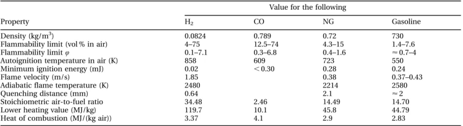
Table 1 compares a number of the combustion-related properties of the two main components of RG, H2, and CO with those of NG and gasoline.
Fuel reforming can be achieved by partial oxida-tion, steam reforming, or autothermal reforming (which combines partial oxidation, steam reforming, and the water–gas shift reaction). In practical onboard applications, fuel reforming may be accomplished using EGR as the source of steam and enthalpy. For more details about fuel reforming and its application on board vehicles, see references [3] to [6].
H2is an alternative energy carrier which produces
non-toxic gases when combusted in air. The density of H2 is one order of magnitude lower than that of
NG, which makes it an undesirable fuel for mobile applications. H2has a wider flammability limit than
NG, especially on the lean side. Its autoignition temperature is higher than that of NG, which makes it theoretically a higher-octane fuel. However, the low minimum ignition energy of H2 reduces its
su-perb resistance to autoignition in practical systems. The lower heating value of H2 is three times that
of NG, but its low density and high air-to-fuel ratio reduces the energy-carrying capacity of H2at a
simi-lar air-to-fuel ratio compared with NG. Hence, H2
enrichment of NG-fuelled SI engines is not expec-ted to lead to an increase in engine power under similar conditions.
1.2 Previous research
H2 or RG enrichment has been studied for many
years. The early studies investigated the effect of H2
enrichment on flames under standard temperature and pressure conditions, and later under elevated pressures and temperatures that simulate actual Table 1 Combustion-related properties of NG, H2, CO, and gasoline from reference [2]
Property
Value for the following
H2 CO NG Gasoline
Density (kg/m3) 0.0824 0.789 0.72 730
Flammability limit (vol % in air) 4–75 12.5–74 4.3–15 1.4–7.6 Flammability limit Q 0.1–7.1 0.3–6.8 0.4–1.6 < 0.7–4
Autoignition temperature in air (K) 858 609 723 550
Minimum ignition energy (mJ) 0.02 , 0.30 0.28 0.24
Flame velocity (m/s) 1.85 0.38 0.37–0.43
Adiabatic flame temperature (K) 2480 2214 2580
Quenching distance (mm) 0.64 2.1 < 2
Stoichiometric air-to-fuel ratio 34.48 2.46 14.49 14.70
Lower heating value (MJ/kg) 119.7 10.1 45.8 44.79
internal combustion engine conditions. These stu-dies have focused on flame development using both stationary combustion chambers and internal com-bustion engines.
One group of H2 enrichment studies focused on
the burning velocities of flames. The laminar burn-ing velocities of binary and tertiary mixtures of H2,
CO, and methane (CH4) were studied in a
funda-mental experifunda-mental study by Scholte and Vaags [7]. Rauckis and McLean [8] operated a Waukesha Co-operative Fuel Research (CFR) engine with up to 30 per cent H2 enrichment. It was found that H2
enrichment primarily affects the ignition delay (or flame kernel growth). Heywood and Vilchis [9] reported that the H2enrichment effect was primarily
on the rapid initial flame development (mostly controlled by the laminar flame speed) and a faster (by a factor of 2) fully developed turbulent flame. Recently Halter et al. [10] found that H2 enhanced
small-scale flame front wrinkling in the turbulent zone.
Milton and Keck [11] found that a double-peak burning velocity behaviour of H2 enriched the
pro-pane flame with increasing pressure using a con-stant-volume combustion chamber. Rafael and Sher [12] tried to explain the double-peak behaviour of the flame speed that was observed by Milton and Keck using a numerical model with 169 elementary reactions and complex H2oxidation mechanisms.
Yu et al. [13] defined a parameter for H2
enrich-ment based on mixture molar ratios. They found that increasing the H2 enrichment parameter leads to
a linear increase in the laminar burning velocity of the mixture. Recently studies by Coppens et al. [14], Mandilas et al. [15], and Di Sarli and Benedetto [16] examined the effect of H2 on the laminar burning
velocities of CH4, both experimentally and
numeri-cally.
A second group of studies investigated the knock characteristics of H2, CO, and their blends with
con-ventional fuels. Rafael and Sher [17] found that H2
retarded the autoignition of n-butane owing to a reduction in the OH concentration in the second stage of reactions that provides OH for the main com-bustion stage. Li et al. [18] found that the excellent knock resistance property of CO deteriorated signifi-cantly with the presence of small amounts of H2,
CH4, or H2O. Hence, it is not expected that RG will
not benefit from the high knocking resistance of dry CO owing to the presence of H2O in the
recir-culated exhaust gases. Li and Karim [19] found that CH4 addition is more effective than CO addition
for improving the knocking resistance
characteris-tics in a H2-fuelled SI engine. They also found that
H2 addition did not significantly affect NOx
emis-sions near stoichiometric conditions, but that NOx
emissions increased significantly when the mix-ture became lean [20]. Topinka et al. [21] found that RG (H2–CO mixture) inhibited knock by
slow-ing the autoignition chemistry and by slightly in-creasing the flame speed. They assumed octane numbers of 106 and 140 for CO and H2respectively.
They estimated that, if 15 per cent of the primary reference fuel is converted to RG, the octane num-ber of the resulting fuel will be approximately ten numbers higher.
A third group of studies focused on SI engine performance and emissions under H2-enriched
con-ditions. Nagalingam et al. [22] found that H2
enrich-ment decreased power and efficiency and increased NOx emissions at constant air-to-fuel ratio and no
EGR. Karim et al. [23] noted that CH4 replacement
with H2 leads to reduced energy delivery at
con-stant intake conditions since CH4 has 54 per cent
more energy content at stoichiometric conditions. H2-enriched combustion increased the H2O
con-tent of the residual gases, improving power and efficiency owing to a faster flame speed, reduced combustion duration, and optimized combustion timing, especially in lean conditions, reduced emis-sions of CO, CH4, and CO2, and increased NOx
emis-sions.
Isherwood et al. [24] decreased engine start-up emissions, replacing RG for HC by 80 per cent and CO by 40 per cent. Shrestha and Karim [25] reported an optimum value of 20–25 vol % for H2enrichment
of a CH4-fuelled SI engine. This suggests that only a
small amount of H2is needed to improve SI engine
performance to compensate for flame depletion under lean combustion conditions. Kirwan et al. [26] reported that using partial oxidation products signifi-cantly reduced HC emissions during cold starting and reduced the catalyst warm-up period consider-ably. Blending gasoline with 30 per cent partial oxidation reforming products reduced NOxemissions
by between 55 and 85 per cent by increasing the EGR limit. Smith and Bartley [27] reported the EGR tolerance enhancement of an NG SI engine to be 44 per cent more than the baseline case. They utilized the synthesis gas in the EGR system by us-ing a partial oxidation CH4 catalyst. Allenby et al.
[28] investigated the potential to expand the EGR limit of an NG-fuelled SI engine using reformer pro-ducts (H2and CO) of an exhaust catalytic fuel
proces-sor. It was found that for indicated mean effective pressures (IMEP) between 2 and 4 bar and 25 per
cent EGR at fixed combustion timing, 5–25 per cent H2 in the EGR stream was required (depending
on the load) to maintain the combustion cyclic variations (as measured by the coefficient of vari-ation (COV) of IMEP) below 5 per cent. Bauer and Forest [29, 30] used the CFR engine and reported that increasing the H2fraction by up to 60 vol %
de-creased the brake-specific CO2by 26 per cent,
brake-specific CO by 40 per cent, and brake-brake-specific HC by 60 per cent, and increased brake-specific NOx
by 30 per cent. During simulating driving cycles, it was found that there is an optimum range of H2
enrichment that benefits both urban and the highway driving cycles for maximum efficiency and minim-um emissions.
Kirwan et al. [31] reported a decrease of 75 per cent in HC emissions using RG during cold starting. Tunesta˚l et al. [32] found that H2 is more effective
when used in slower combustion chamber designs than in faster designs. Quader et al. [33] found that RG enhances the lean limit from Q 5 0.7 to Q 5 0.4 (44 per cent leaner) and EGR tolerance from 15 per cent to 37 per cent (115 per cent higher) while keeping COVimep, 3 per cent. It was found that EGR limit
expansion is a more effective strategy than lean limit expansion. Tully and Heywood [34] used a plasma-tron fuel reformer to study the effect of reformer gas addition to a gasoline SI engine. The study found that using plasmatron fuel reformer increases the fuel conversion efficiency by up to 12.3 per cent. In a recent study by Allgeier et al. [35], an SI engine was operated in all modes using gasoline enriched with reformer gas produced by partial oxidation. The strategy was to use reformer gases to achieve near-zero HC emissions during cold starting, and excess air to produce a highly exothermal reaction that enhanced catalyst warm-up, and finally to use a certain amount of reformer gases under low and medium loads to increase efficiency and to reduce NOxemissions.
Czerwinski and Comte [36] examined the effect of RG on the performances of two small gasoline SI engines. They reported an EGR limit expansion from 7 per cent to 55 per cent and lean limit (relative air-to-fuel ratio) expansion from l 5 1.1 to l 5 2.55. Alger et al. [37] found that adding 0.2 per cent and 0.4 per cent H2 to the intake system improved the
EGR limit to 20–28 per cent and 40–45 per cent respectively.
In addition to the H2 enrichment studies, the
operating characteristics and performance of dedi-cated H2-fuelled SI engines were investigated by
Karim [38] and White et al. [2].
1.3 Current objective
The objective of the current study was to investigate the use of RG to reduce NOxemissions from an NG
SI engine while maintaining high fuel conversion efficiency. The focus was on expansion of the EGR dilution limit; hence the research is considered complementary to that by Rauckis and McLean [8], who altered the air-to-fuel ratio using excess air. In this study, the air-to-fuel ratio was kept constant (l 5 1), but the EGR dilution was increased. This paper examines the effects of simulated RG enrich-ment on the performance characteristics of a relat-ively high-compression-ratio NG-fuelled SI engine operated with a stoichiometric mixture to enable the use of the TWC and different levels of EGR dilution.
2 EXPERIMENTAL SET-UP
All experiments were conducted in a single-cylinder CFR engine. The CFR engine is suitable for investi-gating different combustion strategies, but it should be noted that this engine has very high internal friction and a limited upper speed range. Table 2 shows the CFR engine’s specifications and operating conditions for this study.
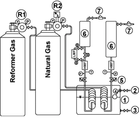
Figure 1 is a schematic diagram of the gaseous fuels supply system. NG was supplied from a high-pressure tank that was filled regularly by ATCO Gas in Edmonton. The natural gas composition on a molar basis was 95.39 per cent CH4, 1.90 per cent
ethane (C2H6), 1.93 per cent N2, and 0.78 per cent
oxygen (O2). An alternative fuel system (AFS) (model
Falcon) electronic double-stage regulator R2 was used to provide a constant NG pressure (80 lbf/in2g (551.5 kPa)) in the delivery line.
Simulated RG with 75 per cent H2and 25 per cent
CO on a volume basis was provided from Praxair high-pressure tanks. The RG pressure in the supply line was adjusted manually using a double-stage Table 2 Waukesha CFR engine specifications and
op-erating conditions
Engine parameter Description or value Combustion chamber Pancake, flat-top piston Compression ratio 11.5, constant
Displacement (cm3) 612
Bore (mm) 82.6
Stroke (mm) 114.3 Engine speed (r/min) 1200 constant
Throttle Wide open, naturally aspirated Spark timing
(deg crank angle (CA))
Maximum for best torque (MBT) (limited to range from 245u to top dead centre (TDC))
pressure regulator R1. The RG pressure was kept constant at 95 lbf/in2g (655 kPa).
The NG and RG feed lines were routed through a liquid–gas heat exchanger 1. Warm building water was supplied to the heat exchanger 2 and was drained continuously 3 to keep the NG and RG temperatures constant at 35 uC. The NG line was equipped with a high-mass flowmeter (HMF) cali-brated in the range 0–50 standard l/min. The RG line was equipped with a low-mass flowmeter (LMF) and an HMF to ensure maximum accuracy of RG mass flow measurement. The flowmeters were cali-brated in the ranges 0–5 standard l/min and 0–50 standard l/min respectively. A series of Swagelok stainless steel ball valves was used to switch the flow between the two mass flowmeters. Two pressure-rated vessels 6 were used downstream of the flow-meters and upstream of the injectors to dampen the injection pressure waves in the fuel delivery lines. The AFS gaseous fuel injectors were used to deliver both NG and RG to the intake plenum.
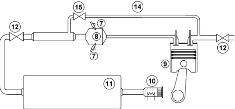
Figure 2 is a schematic diagram of the main ex-perimental hardware. The NG and RG injectors 7 were installed in the intake plenum 8 of the CFR engine 9. A hot-wire anemometer 10 was used to measure air mass flowrates. A 220-l drum 11 was installed in the intake system to dampen air pul-sations. The throttling valve 12 was kept wide open during experiments. EGR flow 14 was initiated by
restricting the exhaust with a back pressure valve 12 and controlled using an EGR valve 15.
Gas analysers manufactured by Analytical Instru-ments were used to measure the NOx, HC, CO, CO2,
and O2 exhaust emissions. The EGR level was
def-ined as the ratio of CO2volumetric concentration in
the intake to that in the exhaust. The CO2 analyser
was also used to measure the CO2 concentration in
the intake plenum to quantify the EGR rate.
National Instruments’ data acquisition hardware and software (LabviewTM) were used to acquire experimental data. Engine mean operating para-meters were collected on a cycle basis and were averaged over the entire cycle (flowrate, pressure, and temperature). A Kistler 6043A water-cooled pres-sure transducer was used to meapres-sure the cylinder pressure. The pressure trace was collected with 0.1u crank angle resolution for 100 consecutive cycles in raw voltage format. MATLABH was used to cali-brate reference and filter noise from the pressure traces. The Rassweiler–Withrow method [39] was applied to compute the mass fraction burned using the PTrAn software package supplied by Optimum Power Technology. The measurement error bars in the figures calculated using an external error analysis technique represent 95 per cent confidence intervals (¡2sn 2 1).
Since the RG (75 per cent H2and 25 per cent CO)
contains O2, the relative air-to-fuel ratio l was
calculated using the chemical valences of the reac-tants (C, +4; H, +1; O, 22; N, 0) considering both NG and RG as fuels. The RG mass fraction was calcu-lated using
RG mass %ð Þ~ 100 _mmRG _
m
mRGzmm_NG
The experiments were conducted in the steady state conditions with an engine speed N 5 1200 r/min, wide-open throttle (WOT) at atmospheric intake pressure, MBT spark timing, and a stoichio-metric air-to-fuel ratio (l 5 1). The NG flowrates were adjusted during the experiments as the EGR fraction and RG blending were varied to keep l 5 1 constant.
Based on Heywood’s [40] definition, MBT spark timing was considered to be the operating point where the IMEP is maximum, subject to the req-uirement that the COVimep is acceptable. Since the
spark timing’s reading was made with a stroboscope light and scale on the flywheel and the torque curve at constant speed near TDC is quite flat [40], it is estimated that the tolerance associated with the MBT spark timings is ¡2u CA.
3 RESULTS AND DISCUSSION 3.1 Natural gas baseline
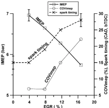
As the engine speed (5 1200 r/min) and l (5 1) were kept constant during the experiments, baseline en-gine operation fuelled by NG was affected only by the spark timing and EGR fraction. Figure 3 shows that the IMEP increased as the spark timing was advanced up until the knock limit when the EGR level of 0 per cent was encountered. In order to operate with further advanced spark timings, in-creasing levels of EGR had to be applied, which
eventually led to much higher cyclic variations in IMEP.
Figure 4 shows that the IMEP decreased and the COVimep increased with increasing EGR level while
maintaining the MBT spark timing. As expected, more advance spark timings were required to keep the combustion timing optimal at higher EGR levels. Figure 5 shows that there is a nearly linear decrease in NOx emissions as the EGR level is
increased. Moreover, indicated specific fuel con-sumption and CO emissions also decreased when the EGR level was increased to 8 per cent. The experimental data suggest that there is a maximum tolerance to an EGR level of 12 per cent for these operating conditions. There is a sharp increase in Fig. 2 Schematic diagram of the main experimental set-up hardware
Fig. 3 Effect of spark timing on the engine’s IMEP and COVimep(base-line test: CFR engine;
compres-sion ratio, 11.5; N 5 1200 r/min; EGR level, 0–16 per cent; l 5 1; dedicated NG) (CAD, bTDC, degrees crank angle before top dead centre)
HC and CO emissions, as well as indicated specific fuel consumption, as a result of the reduced burn-ing velocity, retarded combustion timburn-ing, and low
combustion temperatures that occur at high levels of EGR when the engine is operated with NG.
3.2 RG blending: operating region
The CFR engine was operated using NG blended with various RG mass fractions and EGR rates while keeping an overall stoichiometric air–fuel mixture. The spark timing was adjusted for MBT at each operating point. The RG–EGR operating range ob-tained from all experimental data points is shown in Fig. 6.
As indicated in the previous section, the EGR dilution limit for baseline operation with NG was 12 per cent EGR. Figure 6 shows that increasingly higher levels of EGR can be tolerated as the RG mass fraction increases. However, the limit for EGR dilution was found to be 40 per cent, beyond which reasonable combustion stability could not be achieved with any level of RG.
The spark timing adjustment system on the CFR engine used in this study was limited to spark timings before TDC. However, the MBT spark timing becomes more retarded as the RG mass fraction is increased at a given EGR level, as shown in Fig. 7. Thus, the current experiments were limited to con-ditions where the MBT spark timing occurred up to TDC. Beyond that, further increases in RG were not possible because the engine could not be retarded to the MBT spark timing.
Fig. 4 Effect of the EGR level on the IMEP, COVimep,
and MBT (base-line test: CFR engine; compres-sion ratio, 11.5; N 5 1200 r/min; l 5 1; dedicated NG) (CAD, bTDC, degrees crank angle before top dead centre)
Fig. 5 Effect of the EGR level on the indicated specific (is) emissions and indicated specific (fuel con-sumption (isfc)) (base-line test: CFR engine; compression ratio, 11.5; N 5 1200 r/min; l 5 1; dedicated NG)
Fig. 6 The engine’s EGR–RG operating map (CFR en-gine; compression ratio, 11.5; N 5 1200 r/min; l 5 1; RG-blended NG)
The RG mass fraction was increased to slightly less than 100 per cent during the experiments, where possible. However, an RG mass fraction of 30–35 per cent is reasonable. Figure 6 shows that increasing the RG mass fraction from 0 per cent to 35 per cent increased the EGR tolerability of the engine from 12 per cent to 35 per cent.
3.3 RG enrichment: engine performance
There was no expectation that RG addition would increase the IMEP significantly because the volu-metric energy density of RG is much lower than that of NG and the mixture stoichiometry was held con-stant. Any observed IMEP improvement would be due to improved combustion stability, more optim-ized combustion timing, or less flame kernel deple-tion at highly diluted condideple-tions.
Figure 8 shows that the IMEP increased slightly at lower RG levels for EGR levels up to 30 per cent. As the EGR level increased, the appropriate RG mass fraction required to optimize IMEP was also found to increase. If more than the optimal RG fraction was added, the IMEP decreased gradually. The experimental data also indicate that it is possible to operate the engine at WOT over the IMEP range 4.5–7 bar with an appropriate level of EGR and with RG addition.
Figure 9 shows that, for EGR levels of 0–30 per cent, RG addition reduced the combustion instability, as measured by COVimep. For EGR levels below 12
per cent, RG addition reduced the cyclic variations in IMEP. The RG addition was required to maintain acceptable combustion stability above 12 per cent EGR. Beyond 40 per cent EGR, acceptable combus-tion stability could not be achieved with any level of RG addition. This is probably due to the relatively Fig. 7 Effect of increasing the RG on the MBT spark
timing (CFR engine; compression ratio, 11.5;
N 5 1200 r/min; l 5 1; RG-blended NG)
Fig. 8 Effect of increasing the RG on the IMEP (CFR engine; compression ratio, 11.5; N 5 1200 r/min; l 5 1; RG-blended NG)
Fig. 9 Effect of increasing the RG on the COVimep
reduction (CFR engine; compression ratio, 11.5;
quiescent conditions inside the combustion chamber of the CFR engine and not the combustion phenom-enon itself. This engine experiment was not set up with particular consideration of fuel–air–EGR mixing or charge stratification around the spark plug. At high EGR rates, the combination of a highly diluted mix-ture and the high octane numbers of NG, H2, and
CO, as well as no charge stratification inside the combustion chamber, led to unacceptable combus-tion stability. However, it should be noted that with RG addition and EGR levels of 30–40 per cent, the cyclic variations were lower than those measured for baseline engine operation with NG.
The indicated fuel conversion efficiency is plotted as a function of RG mass fraction and EGR level in Fig. 10. For each EGR level, there is a desirable level of RG addition to optimize the indicated fuel con-version efficiency. The maximum efficiency points are shown in the banded region of the figure. As ex-pected, the optimal RG addition to reduce IMEP cyclic variations and to optimize the combustion timing increases with increasing EGR level.
Figure 10 shows that increasing EGR level leads to higher indicated thermal efficiency independent of the RG. Use of EGR raises the wall temperatures during the intake and compression strokes as well as reducing peak combustion temperature. As described by Hey-wood [40], these effects reduce expansion stroke heat losses and increase indicated combustion efficiency,
provided that the EGR quantity is not sufficient to affect the combustion stability and duration severely. However, the combustion stability and burning velo-city degrade when higher levels of EGR are used without RG. For example, use of 20 per cent EGR required 10 per cent RG to stabilize ignition and use of 20 per cent RG to speed combustion sufficiently for optimum thermal efficiency. The degradation of indic-ated fuel conversion efficiency for greater RG blend fractions greater than optimum may be attributed to increased heat losses due to the heat transfer con-tribution of hydrogen and water vapour.
The indicated fuel conversion efficiency is sig-nificantly affected by apparent combustion effi-ciency, and engine output is further affected by volumetric efficiency. The combustion efficiency accounts for losses due to unburned fuel or in-complete combustion, while the volumetric effi-ciency accounts for losses that occur during the gas exchange processes. RG addition effects on the com-bustion and volumetric efficiencies for experiments conducted with nominal 30 per cent EGR are indicated in Fig. 11. For the 30 per cent EGR case, 20 per cent RG was required to achieve reliable ignition but the figure shows that increasing the RG level from 20 per cent to 30 per cent raises the combustion efficiency from 92 per cent to 95 per cent. Further RG addition did not have a significant effect on combustion efficiency. On the other hand, the volumetric efficiency was quite low because of the 29 per cent EGR employed. The volumetric efficiency decreased monotonically with increasing
Fig. 10 Effect of increasing the RG on the fuel conversion efficiency (CFR engine; compres-sion ratio, 11.5; N 5 1200 r/min; l 5 1; RG-blended NG)
Fig. 11 Effect of the RG on the combustion efficiency and volumetric efficiency (EGR level, 28.8 ¡ 0.7 per cent; l 5 0.99 ¡ 0.02)
RG blend fraction. The gas exchange loss continu-ously increases with increasing RG blend fraction because of the reduced ability of the engine to draw air when NG is replaced with lower-density RG.
3.4 RG enrichment: combustion analyses
The cylinder pressure data were analysed to investi-gate the effect of RG addition on the combustion process for the data points with an EGR level of 28.8 ¡ 0.7 per cent and l 5 0.99 ¡ 0.02. The RG blend fraction covered the wide range 18.0–95.1 per cent.
Figure 12 shows the effect of RG mass fraction on the combustion events as determined using a mass fraction burn (MFB) analysis of the cylinder pressure data. This figure shows the MBT spark timing, as well as the location of the 10 per cent MFB (CA10), 50 per cent MFB (CA50), and 90 per cent MFB (CA90). Increasing the RG blend fraction at constant initial conditions (constant EGR fraction and constant l) significantly retarded the MBT spark timing but did not have a large effect on the timing of the CA10, CA50, and CA90 combustion phasing. However, the ignition delay between the spark timing and the CA10 combustion event was reduced significantly as the RG blend fraction increased. The combustion
duration, if defined as the CA difference between CA10 and CA90, was fairly constant over the wide range of RG blend fractions investigated. This result confirms the observations in earlier fundamental studies that H2 enhances the flame kernel
develop-ment stage but does not significantly affect the fully developed turbulent flame speed.
Comparing the two cases with RG mass fractions of 18 per cent and 29 per cent, the mean ignition delays were not significantly different. However, the combustion stability was greatly enhanced, which led to a more consistent combustion event from cycle to cycle. This is manifested in smaller error bars in the timings of the various combustion events and reduced cyclic variations in the IMEP, as shown previously in Fig. 9.
3.5 RG enrichment: emissions
So far, it has been demonstrated that RG enrichment extends the EGR limits for an NG-fuelled SI engine and increases combustion stability. It is well known that EGR is a relatively simple way to reduce the peak temperatures inside the combustion chamber for the purposes of significantly reducing NOx
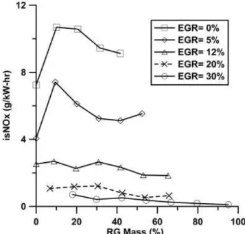
emissions. Figure 13 demonstrates the use of RG enrichment to enable an SI engine to operate at high EGR rates with extremely low NOxemissions.
Fig. 12 Effect of the RG on the combustion events of spark timing (SI) (CA10, CA50, and CA90; EGR level, 28.8 ¡ 0.7 per cent; l 5 0.99 ¡ 0.02) (CAD, aTDC, degrees crank angle after top dead centre)
Fig. 13 Effect of increasing the RG on the indicated specific (is) NOxemissions (CFR engine;
com-pression ratio, 11.5; N 5 1200 r/min; l 5 1; RG-blended NG)
Figure 13 shows that the baseline NOx emissions
without EGR for the SI engine fuelled with NG under the prescribed conditions were greater than 7 g/kW h. RG addition allowed the engine to be operated with 30 per cent EGR, which reduced the NOx
em-issions by roughly one order of magnitude, depen-ding on the RG mass fraction.
One of the challenges associated with the use of EGR is an increase in unburned HC emissions. Figure 14 shows that HC emissions increase from 4 g/kW h to around 8 g/kW h for the operating region of 20–30 per cent EGR and 20–30 per cent RG mass fraction, even though the spark timing was adjusted for MBT. Higher EGR rates reduce combustion temperatures and lower the late-cycle HC oxidation rate.
Figure 14 also shows that RG addition tends to compensate somewhat for the HC emission increase associated with EGR. This is a natural result of reducing the carbon content of the fuel by adding a more hydrogenated fuel component (in this case, RG). The increase in the H-to-C ratio of the fuel that results from RG addition leads to a reduction in the HC emissions.
The effect of EGR and RG addition on CO emissions is shown in Fig. 15. The CO emissions were found to decrease as the RG mass fraction increased from 0 per cent to 20 per cent. This is believed to be due to improvements in the combustion stability as the RG mass fraction increases. However, CO emissions tend
to increase for RG mass fractions greater than 20 per cent. This may be due to the higher CO content of the fuel and increased quenching of the CO-to-CO2
oxidation reaction as the RG mass fraction increases. It may also be due to CO present in the RG
Fig. 14 Effect of increasing the RG on the indicated specific (is) HC emissions (CFR engine; com-pression ratio, 11.5; N 5 1200 r/min; l 5 1; RG-blended NG)
Fig. 15 Effect of increasing the RG on the indicated specific (is) CO emissions (CFR engine; com-pression ratio, 11.5; N 5 1200 r/min; l 5 1; RG-blended NG)
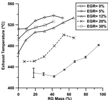
Fig. 16 Effect of increasing the RG on exhaust tem-perature (CFR engine, compression ratio, 11.5;
(25 mass %) which finds its way into the exhaust stream during the valve overlap period.
3.6 Efficiency–emissions trade-off
The objective of this study was to investigate the addition of partially reformed NG into an NG-fuelled SI engine to extend the EGR limit and to reduce NOx
emissions. The engine was operated under stoichio-metric conditions assuming that a TWC would also be used to reduce NOx, HC, and CO emissions
further. In this section, this strategy will be assessed in terms of NOx emission reduction and its impact
on overall system efficiency.
For discussion purposes, the NOxemissions will
be compared with the EPA standard of 0.2 g/bhp h for heavy-duty highway engines for model year 2007 and later. The equivalent indicated specific NOxemissions standard in SI units would be
appro-ximately 0.22 g/kW h, assuming a 20 per cent loss in going from indicated to brake power values.
Figure 13 shows that the baseline NOxemissions
of 7 g/kW h can be reduced to approximately 0.5 g/kW h by adding 30 per cent mass fraction RG, which enables operation with 30 per cent EGR. The exhaust gas temperature under these conditions is approximately 425 uC, as shown in Fig. 16. A TWC should have an NOxreduction efficiency of
approxi-mately 80 per cent under these conditions. This should enable NOx emissions of 0.1 g/kW h to be
achieved, which would meet the 2007 EPA emission standard for heavy-duty engines with a reasonable margin of safety.
If attention is switched to overall system effi-ciency, Fig. 10 shows that the indicated specific fuel conversion efficiency increases from 35 per cent to 40 per cent by the use of 30 per cent RG mass fraction and 30 per cent EGR. This corresponds to a 14 per cent increase in fuel conversion efficiency. On the other hand, the generation of 30 per cent RG mass fraction with an 80 per cent efficient fuel reformer will suffer from a 6 per cent reduction in efficiency. Since the increase in fuel conversion efficiency is greater than the loss in efficiency due to fuel reforming, it is reasonable to assume that the fuel reforming process will not lead to a compromise in the overall engine efficiency while achieving NOx
emissions below 0.2 g/kW h owing to the extended EGR limit.
In summary, the approach of using fuel reforming to extend the EGR limit of an NG-fuelled SI engine appears to be a potentially attractive method for reducing NOx emissions below 0.2 g/kW h without
compromising the fuel conversion efficiency of the engine.
4 CONCLUSIONS
Simulated reform gas enrichment (75 per cent H2
and 25 per cent CO) to expand the EGR limit and to reduce NOxemissions from an NG-fuelled SI
en-gine was investigated. The effects of RG enrichment and EGR dilution on the performance, combus-tion behaviour, and emissions from a CFR engine operated with stoichiometric fuel–air mixtures, to enable the use of the TWC, were reported.
When the engine was fuelled with NG, the max-imum EGR tolerance was 12 per cent owing to retarded combustion timing and excessive cyclic variations in the combustion process. The addition of RG expanded the maximum EGR tolerance to approximately 40 per cent. Engine-out indicated specific NOxemissions below 1 g/kW h were typically
achieved when the RG blend fraction and EGR levels were greater than 20 per cent. The NOx emissions
could be further reduced to meet a stringent future standard (e.g. the US EPA 2007 emissions standard for on-highway heavy-duty diesel engines) using a TWC. The TWC is needed to oxidize the higher HC emissions produced with increasing EGR level.
Increasing the RG blend fraction at constant initial conditions (constant EGR fraction and constant l) significantly retarded the MBT spark timing but did not have a large effect on the timing of the CA10, CA50, and CA90 combustion phasing. However, the ignition delay between the spark timing and the CA10 combustion event was reduced significantly as the RG blend fraction increased.
The optimal RG fraction was found to be just enough to compensate the decrease in the burning velocity due to the EGR level and to return it to the normal values. Adding more RG than the minimum requirement for combustion enhancing caused a penalty in the power and efficiency of the engine.
Overall, a simple energy balance showed that the fuel conversion efficiency increases if an optimal combination of EGR level and RG enrichment is used, which more than compensates for the as-sumed 20 per cent loss of energy associated with the fuel reforming process.
ACKNOWLEDGEMENTS
The authors gratefully acknowledge the contribu-tions of the Auto21 National Centre of Excellence
and the Government of Canada’s Program for Energy Research and Development (PERD/AFTER) in sup-porting this work.
REFERENCES
1 Dieselnet, Emission Standards, 2008, available from http://www.dieselnet.com/standards/. 2 White, C. M., Steeper, R. R., and Lutz, A. E. The
hydrogen-fueled internal combustion engine: a technical review. Int. J. Hydrogen Energy, 2006, 31(10), 1292–1305.
3 Jamal, Y. and Wyszynski, M. L. On-board genera-tion of hydrogen-rich gaseous fuels – a review. Int.
J. Hydrogen Energy, 1994, 19(7), 557–572.
4 Docter, A. and Lamm, A. Gasoline fuel cell systems. J. Power Sources, 1999, 84, 194–200. 5 Dicks, A. L. Hydrogen generation from natural gas
for the fuel cell systems of tomorrow. J. Power
Sources, 1996, 61, 113–124.
6 Naidja, A., Krishna, C. R., Butcher, T., and Mahajan, D. Cool flame partial oxidation and its role in combustion and reforming of fuels for fuel cell systems. Prog. Energy Combust. Sci., 2003, 29, 155–191.
7 Scholte, T. G. and Vaags, P. B. Burning velocities of mixtures of hydrogen, carbon monoxide and methane with air. Combust. Flame, 1959, 3, 511–524.
8 Rauckis, M. J. and McLean, W. J. The effect of hydrogen addition on ignition delays and flame propagation in spark ignition engines. Combust.
Sci. Technol., 1979, 19, 207–216.
9 Heywood, J. B. and Vilchis, F. R. Comparison of flame development in a spark-ignition engine fueled with propane and hydrogen. Combust. Sci.
Technol., 1984, 38, 313–324.
10 Halter, F., Chauveau, C., and Gokalp, I. Charac-terization of the effects of hydrogen addition in premixed methane/air flames. Int. J. Hydrogen
Energy, 2007, 32(13), 2585–2592.
11 Milton, B. E. and Keck, J. C. Laminar burning velocity in stoichiometric hydrogen and hydrogen-hydrocarbon gas mixtures. Combust. Flame, 1984, 58, 13–22.
12 Rafael, S. and Sher, E. Reaction kinetics of hydrogen-enriched methane–air and propane–air flames. Combust. Flame, 1989, 78(3–4), 326–338. 13 Yu, G., Law, C. K., and Wu, C. K. Laminar flame
speeds of hydrocarbon + air mixtures with hydro-gen addition. Combust. Flame, 1986, 63, 339–347. 14 Coppens, F. H. V., De Ruyck, J., and Konnov, A. A.
Effects of hydrogen enrichment on adiabatic burn-ing velocity and NO formation in methane + air flames. Exp. Thermal Fluid Sci., 2007, 31(5), 437–444.
15 Mandilas, C., Ormsby, M. P., Sheppard, C. G. W., and Woolley, R. Effects of hydrogen addition on laminar and turbulent premixed methane and
iso-octane–air flames. Proc. Combust. Inst., 2007, 31(1), 1443–1450.
16 Di Sarli, V. and Benedetto, A. D. Laminar burn-ing velocity of hydrogen–methane/air premixed flames. Int. J. Hydrogen Energy, 2007, 32(5), 637–646.
17 Refael, S. and Sher, E. Autoignition of hydrogen-enriched n-butane–air mixture: a theoretical study. In Proceedings of the 23rd International Sympo-sium on Combustion, Orleans, France, 22–27 July 1990, 1991, Vol. 1, pp. 1789–1796 (Combustion Institute, Pittsburgh, Pennsylvania).
18 Li, H., Karim, G. A., and Sohrabi, A. Knock and combustion characteristics of CH4, CO, H2 and
their binary mixtures. SAE paper 2003-01-3088, 2003.
19 Li, H. and Karim, G. A. Knock in spark ignition hydrogen engines. Int. J. Hydrogen Energy, 2004, 29(8), 859–865.
20 Li, H. and Karim, G. A. Exhaust emissions from an SI engine operating on gaseous fuel mixtures containing hydrogen. Int. J. Hydrogen Energy, 2005, 30(13–14), 1491–1499.
21 Topinka, J. A., Gerty, M. D., Heywood, J. B., and Keck, J. C. Knock behavior of a lean-burn, H2and
CO-enhanced, SI gasoline engine concept. SAE paper 2004-01-0975, 2004.
22 Nagalingam, B., Duebel, F., and Schmillen, K. Performance study using natural gas, hydrogen-supplemented natural gas and hydrogen in AVL research engine. Int. J. Hydrogen Energy, 1983, 8(9), 715–720.
23 Karim, G. A., Wierzba, I., and Al-Alousi, Y. Methane–hydrogen mixture as fuel. Int. J. Hydrogen
Energy, 1996, 21(7), 625–631.
24 Isherwood, K. D., Linna, J.-R., and Loftus, P. J. Using on-board fuel reforming by partial oxidation to improve SI engine cold-start performance and emissions. SAE paper 980939, 1998.
25 Shrestha, S. O. B. and Karim, G. A. Hydrogen as an additive to methane for spark ignition engine applications. Int. J. Hydrogen Energy, 1999, 24, 466–475.
26 Kirwan, J. E., Quader, A. A., and Grieve, M. J. Advanced engine management using on-board gasoline partial oxidation reforming for meeting super-ULEV (SULEV) emissions standards. SAE paper 1999-01-2927, 1999.
27 Smith, J. A. and Bartley, G. J. J. Stoichiometric operation of a gas engine utilizing synthesis gas and EGR for NOx control. Trans. ASME, J. Engng
Gas Turbines Power, 2000, 122, 617–623.
28 Allenby, S., Chang, W.-C., Megaritis, A., and Wyszyn´ ski, M. L. Hydrogen enrichment: a way to maintain combustion stability in a natural gas fuelled engine with exhaust gas recirculation, the potential of fuel reforming. Proc. Instn Mech. Engrs,
Part D: J. Automobile Engineering, 2001, 215,
405–418.
29 Bauer, C. G. and Forest, T. W. Effect of hydrogen addition on the performance of methane-fueled
vehicles. Part I: effect on S.I. engine performance.
Int. J. Hydrogen Energy, 2001, 26(1), 55–70.
30 Bauer, C. G. and Forest, T. W. Effect of hydrogen addition on the performance of methane-fueled vehicles. Part II: driving cycle simulations. Int. J.
Hydrogen Energy, 2001, 26(1), 71–90.
31 Kirwan, J. E., Quader, A. A., and Grieve, M. J. Fast start-up on-board gasoline reformer for near-zero emissions in spark-ignition engines. SAE paper 2002-01-1011, 2002.
32 Tunesta˚l, P., Christensen, M., Einewall, P., An-dersson, T., Johansson, B., and Jo¨nsson, O. Hydro-gen addition for improved lean-burn capability of slow- and fast-burning natural gas combustion chambers. SAE paper 2002-01-2686, 2002.
33 Quader, A. A., Kirwan, J. E., and Grieve, M. J. Engine performance and emissions near the dilute limit with hydrogen enrichment using an on-board reforming strategy. SAE paper 2004-01-1356, 2004. 34 Tully, E. J. and Heywood, J. B. Lean-burn char-acteristics of a gasoline engine enriched with hydrogen from a plasmatron fuel reformer. SAE paper 2003-01-0630, 2003.
35 Allgeier, T., Klenk, M., Landenfeld, T., Conte, E., Boulouchos, K., and Czerwinski, J. Advanced emission and fuel economy concept using com-bined injection of gasoline and hydrogen in SI engines. SAE paper 2004-01-1270, 2004.
36 Czerwinski, J. and Comte, P. Addition of CNG and reformer gas to the gasoline-fuelled SI engine. SAE paper 2004-01-0973, 2004.
37 Alger, T., Gingrich, J., and Mangold, B. The effect of hydrogen enrichment on EGR tolerance in spark-ignited engines. SAE paper 2007-01-0475, 2007. 38 Karim, G. A. Hydrogen as a spark ignition engine
fuel. Int. J. Hydrogen Energy, 2003, 28, 569–577. 39 Arrigoni, V., Cornetti, G., Gaetani, B., and Ghezzi,
P. Quantitative systems for measuring knock. Proc.
Instn Mech. Engrs, 1972, 186, 575–583.
40 Heywood, J. B. Internal combustion engine
funda-mentals, 1988 (McGraw-Hill, New York).
APPENDIX Notations
CAX timing of X per cent of maximum
mass fraction burned on the degrees crank angle basis
COVimep coefficient of variation in the
indicated mean effective pressure (per cent)
EGR exhaust gas recirculation
HC total of methane and non-methane
unburned hydrocarbons
IMEP indicated mean effective pressure
(bar)
MBT maximum for best torque (spark
timing)
MFB mass fraction burned
NG natural gas (mostly CH4with traces
of C2H6, N2, and CO2)
NOx nitrogen oxide (NO, NO2, and N2O)
RG reformer gas
SI spark ignition
TDC top dead centre
TWC three-way catalytic converter
l ratio of actual air-to-fuel ratio to
stoichiometric air-to-fuel ratio sn 2 1 standard deviation of the sampled
data corrected for the mean