The Backseat Control Architecture for Autonomous
Robotic Vehicles: A Case Study with the Iver2 AUV
The MIT Faculty has made this article openly available.
Please share
how this access benefits you. Your story matters.
Citation
Eickstedt, D.P., and S.R. Sideleau. “The backseat control
architecture for autonomous robotic vehicles: A case study with the
Iver2 AUV.” OCEANS 2009, MTS/IEEE Biloxi - Marine Technology for
Our Future: Global and Local Challenges. 2009. 1-8.
Publisher
Institute of Electrical and Electronics Engineers
Version
Final published version
Citable link
http://hdl.handle.net/1721.1/59322
Terms of Use
Article is made available in accordance with the publisher's
policy and may be subject to US copyright law. Please refer to the
publisher's site for terms of use.
The Backseat Control Architecture for Autonomous
Robotic Vehicles: A Case Study with the Iver2 AUV
Donald P. Eickstedt and Scott R. Sideleau
Naval Undersea Warfare Center, Division NewportNewport, RI 02421
Email: [email protected]; [email protected]
Abstract— In this paper, an innovative hybrid control
architec-ture for real-time control of autonomous robotic vehicles is de-scribed as well as its implementation on a commercially available autonomous underwater vehicle (AUV). This architecture has two major components, a behavior-based intelligent autonomous controller and an interface to a classical dynamic controller that is responsible for real-time dynamic control of the vehicle given the decisions of the intelligent controller over the decision state space (e.g. vehicle course, speed, and depth). The driving force behind the development of this architecture was a desire to make autonomy software development for underwater vehicles independent from the dynamic control specifics of any given vehicle. The resulting software portability allows significant code reuse and frees autonomy software developers from being tied to a particular vehicle manufacturer’s autonomy software and support as long as the vehicle supports the required interface between the intelligent controller and the dynamic controller. This paper will describe in detail the components of the backseat driver architecture as implemented on the Iver2 underwater vehicle, provide several examples of its use, and discuss the future direction of the architecture.
I. INTRODUCTION
Recent advances in autonomous underwater vehicle (AUV) technology have led to their use in a number of military and civilian applications including anti-submarine warfare, mine countermeasures, environmental sampling, and oilfield surveys among others. This increase in interest and funding has, predictably, led to an increase in the number of commer-cial companies offering AUVs. The number of commercommer-cial AUVs of all size classes as well as the number and types of sensors available for these AUVs has never been greater. Each of these companies, for understandable competitive reasons, has developed their own proprietary vehicle control software. Additionally, the major customers for some of these companies are oilfield survey operations which typically have a low inter-est in any sort of adaptive or cooperative vehicle maneuvering and, therefore, these companies have low interest in providing these capabilities as basic vehicle options. This situation has led to a disconnect with researchers developing applications requiring adaptive AUV autonomy who, for the most part, view underwater vehicles as commodity platforms designed to carry application-specific sensor suites. For this group, code portability and rapid reconfiguration on different vehicles is a major benefit.
This disconnect can be resolved by viewing intelligent vehicle control and dynamic vehicle control as being separable
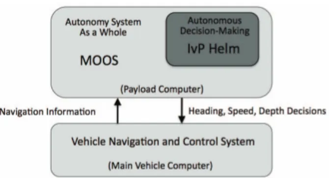
Fig. 1. The backseat driver architecture: The key idea is the separation of vehicle autonomy from vehicle control. The autonomy system provides heading, speed and depth commands to the vehicle control system. The vehicle control system executes the control and passes navigation information, e.g., position, heading and speed, to the autonomy system. The backseat paradigm is agnostic regarding how the autonomy system is implemented, but in this figure the MOOS-IvP autonomy architecture is depicted [1].
components of an overall vehicle control architecture. For our purposes, the intelligent control component is responsible for determining the proper decision over the state space of desired vehicle course, speed, and depth while the dynamic control component is responsible for obtaining and maintaining the desired state by manipulation of the actuator surfaces and thrusters as well as passing navigation information (e.g., posi-tion, heading and speed) to the autonomy system. The general architecture just described has been designated the backseat driver architecture [1] where the intelligent controller can be seen as residing in the backseat and the dynamic controller in the frontseat. In this arrangement, the dynamic controller typically resides on the manufacturer’s main vehicle computer (MVC) and the intelligent controller may reside in a totally separate processor on the vehicle, communicating with the MVC via a network or serial link using a standard interface. Although this architecture can be used with any intelligent controller implementation, Fig. 1 shows it implemented using the MOOS-IvP autonomy system.
This approach allows the intelligent control software to be rapidly portable across many different vehicles with the only additional requirement being the need for an interface module that implements the backseat/frontseat interface for a particular vehicle. Although this paper is focused on the implementation of the backseat driver architecture on the Iver2 AUV, it should be noted that it has also been successfully implemented on the
Bluefin 21, Hydroid Remus, and FAU Ocean Explorer AUVs. The remainder of this paper will describe the implemen-tation of the backseat control architecture on the Iver2 AUV manufactured by Ocean Server Technology based in Fall River, Massachusetts. Section II will describe the major components of the implementation including a detailed description of the Iver2 vehicle and the MOOS-IvP autonomy that supports the intelligent controller. Section III will describe the backseat control interface module that supports the interface between the intelligent controller and the MVC. Section V will show several vehicle runs made using the backseat control inter-face. The paper will conclude by discussing the need for a standardized backseat interface.
II. SYSTEMARCHITECTURE
In this section, we present the general system architecture for the Iver2 AUV equipped with the backseat driver architec-ture. This architecture consists of the Iver2 vehicle equipped with both a main vehicle computer supplied by the manufac-turer as well as as a separate payload computer which hosts the intelligent controller running under the MOOS autonomy mid-dleware [2]. In this implementation, the intelligent controller is the IvP Helm, a behavior-based helm that runs as a single MOOS process and uses multi-objective optimization with the Interval Programming (IvP) model for behavior coordination [3], [4]. The MOOS module iOceanServerComms (described in detail in Section III) provides the backseat/frontseat inter-face via a serial link with the MVC.
A. The Iver2 AUV
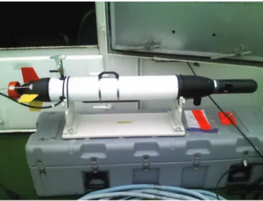
The Iver2 AUV (see Fig. 2) is a small man-portable AUV manufactured in Fall River Massachusetts by Ocean Server Technology, Inc. This vehicle was chosen by the Marine Au-tonomy Group (MAG) at the Naval Undersea Warfare Center in Newport, RI based primarily on the ability to rapidly launch the vehicle from shore or a variety of small or large craft as well as its ability to carry a variety of sensors relevant to our work in adaptive and collaborative autonomy. The vehicle’s small size allows significantly more frequent experimental usage compared with larger vehicles needing ships with large capacity winches for launch and recovery. The MAG currently operates three Iver2 vehicles.
1) General Characteristics: The Iver2 vehicles in the MAG are approximately 65 inches in length and weigh approx-imately 50 pounds. The MAG vehicle is 5 inches longer than the standard vehicle and was lengthened to provide space for additional electronics including a precision clock, inertial measurement unit, and Iridium satellite transceiver. The vehicle can operate at speeds of up to 4 knots using its rechargeable batteries which have600 Wh of capacity. Vehicle endurance is anywhere between 4 and 12 hours depending on the vehicle’s speed and hotel load (e.g. A/D conversion for the acoustic array). The vehicle also comes equipped with integrated depth (pressure) and altitude sensors.
Fig. 2. The Iver2 AUV equipped with the YSI 6600 V2 sonde, Woods Hole Oceanographic Institute acoustic micromodem and a 16-element towed hydrophone array. The payload computer stack consists of a PIII-800 CPU and two 8 channel D/A boards. This model Iver2 navigates on the surface using GPS and underwater using a compass and speed table. This vehicle is de-signed for adaptive and collaborative autonomy experimentation applications including anti-submarine warfare and rapid environmental assessment.
2) Navigation: Each of the Iver2 vehicles in the MAG is equipped with a GPS receiver and three-axis digital compass providing roll, pitch, and yaw. One of the MAG vehicles was recently equipped with a Doppler velocity logger (DVL) to provide closed-loop speed control. The other two MAG vehicles have open-loop speed control using speed tables based on thruster RPM. Navigation solutions are computed on the MVC using dead reckoning and sent to the backseat over the backseat/frontseat interface. In the near future, all MAG vehicles will be equipped with inertial measurement units to provide closed-loop speed control in cases where the DVL is not equipped or cannot be used (e.g. in deep water).
3) Communications: Each of the Iver2 vehicles in the MAG is equipped with WiFi capability for communications while on the surface as well as a Woods Hole Oceanographic Institute acoustic Micromodem for communications while underwater. In the MAG configuration, the WiFi link is operated by the MVC and the acoustic modem is operated by the autonomy system on the payload computer. The acoustic modem is used both for providing status messages to the topside as well as for reception of command and control messages from the topside. In the near future, each MAG Iver2 will be equipped with an Iridium satellite transceiver which will provide status messages while the vehicle is on the surface as well provide for the reception of command and control instructions when the vehicle is out of WiFi or acoustic communications range. 4) Sensors: In the current MAG configuration, each Iver2 vehicle is equipped with a YSI, Inc. 6600V2-4 sensor bulkhead allowing the insertion of many different types of oceano-graphic sensor probes. The current MAG vehicles are equipped with conductivity-temperature, dissolved oxygen, and turbidity probes. Data from these probes is provided to the backseat
autonomy system via the backseat interface in real time, allowing the vehicle to perform real-time adaptive environ-mental sampling. In addition to the oceanographic sensors, each vehicle is equipped with a 16-element acoustic line array cut for acoustic sampling at 1 KHz. Each array is equipped with inline preamplification. The array on each vehicle feeds acoustic data to a set of 8-channel analog to digital (A/D) converter boards described in II-A.5, allowing the vehicle to perform real-time underwater target tracking and localization experiments.
5) Payload Computer: The payload computer stack in the MAG Iver2 consists of a CPU board running an Intel PIII-800 processor with 512 MB of main memory and a 100 GB hard drive. Communications with the MVC is via both a standard10 Mbps Ethernet connection and a standard RS-232 serial link. The Ethernet link is primarily used for communication with the payload computer through the vehicle’s WiFi connection while the serial connection is used for the backseat control interface. In addition to the CPU board, the payload computer stack is equipped with two General Standards 24DSI-12 8-channel A/D converter boards providing 16 channels of simultaneous sigma-delta sampling for the acoustic line array.
B. The MOOS-IvP Autonomy Architecture
The autonomy system on the MAG Iver2 vehicles is im-plemented within the MOOS-IvP architecture for autonomous control, developed and maintained under a GPL license by MIT, Oxford University, and NUWC. MOOS-IvP is com-posed of the Mission Oriented Operating Suite (MOOS), an open source software project for communication between, and nested control and coordination of, software processes running on the individual nodes of a network of autonomous platforms. MOOS-IvP is fully portable and platform independent, but typically implemented under GNU/Linux. MOOS-IvP also contains the IvP Helm, a behavior-based helm that provides the core of the behavior-based control architecture. The IvP Helm runs as a single MOOS process and uses multi-objective optimization with the Interval Programming (IvP) model for behavior coordination [3]. See [5], [6], and [7] for other examples of MOOS-IvP on autonomous marine vehicles.
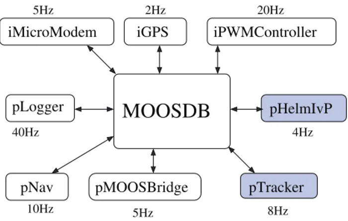
A MOOS community contains processes that communi-cate through a database or bulletin board process called the MOOSDB , as shown in Fig. 3. The MOOSDB process is the core of the MOOS architecture and handles all communication between the processes using a publish-and-subscribe architec-ture. Thus, all processes may publish variable name/value pairs to the MOOSDB. Once a variable has changed, all processes that have registered for subscription to the variable will receive a notification, following which they may request the new variable value if needed. The MOOS processes include all necessary control functions as well as sensing and processing modules, with the MOOSDB providing the unified interface standard that enables the fully autonomous integration of sensing, modeling, processing, and control. MOOS ensures a process executes its Iterate method at a specified frequency and
iPWMController iGPS pMOOSBridge pLogger pTracker iMicroModem pNav
MOOSDB
2Hz 20Hz 5Hz 40Hz 4Hz pHelmIvP 8Hz 5Hz 10HzFig. 3. A MOOS community contains processes that communicate through a database or bulletin board process called the MOOSDB. The MOOSDB process is the core of the MOOS architecture and handles all communication between the processes using a publish-and-subscribe architecture. MOOS may be composed of processes for data logging (pLogger), data fusion (pNav), actuation (iPWMController), sensing (iGPS), communication (pMOOSBridge, iMicroModem), and much more. They can all be run at different frequencies as shown.
handles new mail on each iteration in a publish and subscribe manner.
Each iteration of the helm contains the following steps: (1) mail is read from the MOOSDB, (2) information is updated for consumption by behaviors, (3) behaviors produce an objective function if applicable, (4) the objective functions are resolved to produce a single action, and (5) the action is posted to the MOOSDB for consumption by low-level control MOOS processes. This is illustrated in Fig. 4. Examples of
behavior behavior behavior MOOSDB Information IvPFunction IvPFunction IvPFunction Solver IvP Action pHelmIvP
Fig. 4. The IvP Helm runs as a process called pHelmIvP in a MOOS community. On each iteration, pHelmIvP first uses information from the MOOSDB to compute an objective function over the decision state space of course, speed, and depth for each of the active behaviors. pHelmIvP then resolves these objective function into a single decision of desired vehicle course, speed, and depth. This decision is posted to the MOOSDB for consumption by the vehicle control system.
adaptive behaviors are described in [8]. Adaptive behaviors for oceanographic sampling with the autonomous kayaks are described in [9].
III. THEBACKSEATCONTROLARCHITECTURE
A. Overview
The iOceanServerComms MOOS module forms the inter-face between the main vehicle control system (i.e. MVC or frontseat) and the vehicle autonomy system (i.e. backseat). Regular updates from the vehicle‘s sensors (e.g. compass, GPS, altimeter, oceanographic sensors, etc.) received through the interface (as well as data received from sensors directly connected to the payload computer stack) are placed in the MOOS DB and are used by the IvP Helm to make decisions regarding the desired course, speed, and depth for the vehicle during the next control cycle. The desired course, speed, and depth are then transmitted by the iOceanServerComms module to the frontseat where the dynamic controller will attempt to maintain the desired vehicle state. Typically, this interface is run at a rate of one Hz, which is sufficient to control a vehicle with a maximum speed of four knots. On the MAG Iver2 vehicles, the backseat/frontseat interface utilizes a standard RS-232 serial connection, resulting in the vehicle autonomy system appearing as another simple sensor to the vehicle dynamic control system. Other underwater vehicles such as the Bluefin 21 AUVs use Ethernet connections. Regardless of the connection method, the iOceanServerComms module is responsible for the transmission and processing of NMEA-encoded messages over the interface. The following subsec-tions will describe the contents of each message in detail. Full details are available in [10].
B. Data Request Message
The data request message ($OSD) allows iOceanServer-Comms to request specific sensor messages from the frontseat. Because the MAG Iver2 vehicles are equipped with YSI 6600 oceanographic sensors (providing CTD [conductivity, temperature, depth], turbidity, and dissolved oxygen data), we can currently request updates of five different message types: compass, GPS, vehicle state, vehicle power (i.e. battery controller), and YSI sensors. The data request message is easily expandable by the vehicle manufacturer to facilitate data transmission from other sensors that require connectivity to the vehicle control system. For example, an Iver2 with an integrated Doppler velocity loggger for improved track line following or Inertial Measurement Unit for improved speed control should be capable of reporting each respective sensor‘s data in separate NMEA encoded strings. An example of the NMEA encoded string to request data from the Iver2 frontseat across a serial connection is shown in Table I where each of the five fields, if present as shown, indicates that message is requested from the frontseat.
In response to this message, the frontseat first replies with an acknowledgement ($ACK) that the command was received and processed successfully or that the request was received and not processed due to an error. In response to the ac-knowledgement iOceanServerComms updates the MOOSDB variables FRONTSEAT ACK and FRONTSEAT ACK ERROR which can be used for communications monitoring by the
TABLE I DATA REQUESTMESSAGE
$OSD,C,G,S,P,Y*2A
$OSD Message header C Compass request G GPS request
S State (of vehicle) request
P Power (or battery controller) request Y YSI Sensor request
*2A Standard NMEA checksum (XOR of message contents)
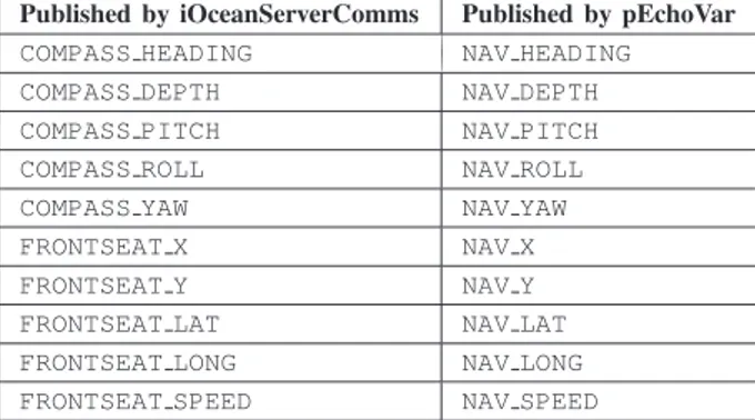
end user or an intermediate MOOS application. If successful, the frontseat then transmits the requested data messages. If a particular message fails the checksum test when decoded by the iOceanServerComms module, it is then discarded. Currently, iOceanServerComms requests and parses all five NMEA messages (six including $ACK) per data request on the MAG Iver2 vehicles. The data polling rate on the MAG vehicles is is one Hz, but frequencies of up to 20 Hz have been tested on the bench and/or in the water. The user must balance the density of data to post-process and the size of the log files generated when considering the rate of data polling. The iOceanServerComms module parses the NMEA mes-sages and updates the appropriate MOOS variables as de-scribed in Tables II through VII. To allow for intermediate manipulation by other MOOS processes and to facilitate the use of other sensors that may be more accurate on the reporting of particular data (e.g. heading), iOceanServerComms does not directly post to the MOOSDB certain critical navigation variables that the IvP Helm monitors. Instead, iOceanServer-Comms publishes data to unique MOOS variables and requires that the user employ the MOOS utility module pEchoVar to re-post data to the correct variables. This method allows, for example, data from an IMU to be posted to the NAV HEADING variable instead of the COMPASS HEADING from the frontseat to be posted to the NAV HEADING variable. On the MAG Iver2 vehicles, pEchoVar currently re-posts the variables pub-lished by iOceanServerComms as shown in Table II.
TABLE II ECHOEDVARIABLES
Published by iOceanServerComms Published by pEchoVar
COMPASS HEADING NAV HEADING COMPASS DEPTH NAV DEPTH COMPASS PITCH NAV PITCH COMPASS ROLL NAV ROLL COMPASS YAW NAV YAW FRONTSEAT X NAV X FRONTSEAT Y NAV Y FRONTSEAT LAT NAV LAT FRONTSEAT LONG NAV LONG FRONTSEAT SPEED NAV SPEED
C. Received Sensor Messages
The following subsections describe the individual MOOS variables that iOceanServerComms updates when receiving a given sensor message.
1) Compass Message: The $C message from vehicle con-trol system’s navigational compass populates the MOOS vari-ables as shown in Table III.
TABLE III COMPASSMESSAGE
Published by iOceanServerComms Purpose
COMPASS YAW Magnetic heading (degrees) COMPASS PITCH Vehicle pitch (degrees) COMPASS ROLL Vehicle roll (degrees)
COMPASS TEMPERATURE Ambient temperature (degrees C) COMPASS DEPTH Vehicle depth (feet)
COMPASS HEADING Calculated true heading (degrees)
2) GPS Message: The $GPRMC message from the vehicle control system populates the MOOS variables shown in Table IV when a stable satellite fix is present.
TABLE IV GPSMESSAGE
Published by iOceanServerComms Purpose
GPS TIME UTC time of day GPS WARNING Satellite fix good?
GPS SPEED Estimated vehicle speed (m/s) GPS HEADING True heading (degrees) GPS DATE UTC date
GPS MAGNETICVARIATION Magnetic variation (degrees) GPS LATITUDE Latitude (decimal degrees) GPS LONGITUDE Longitude (decimal degrees) GPS UPDATE RECEIVED Time of last valid fix
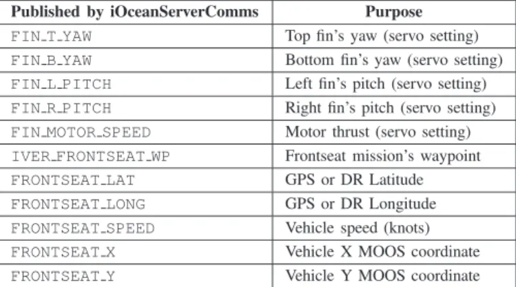
3) State Message: The $OSI message from the vehicle control system populates the MOOS variables as shown in Table V.
TABLE V STATEMESSAGE
Published by iOceanServerComms Purpose
FIN T YAW Top fin’s yaw (servo setting) FIN B YAW Bottom fin’s yaw (servo setting) FIN L PITCH Left fin’s pitch (servo setting) FIN R PITCH Right fin’s pitch (servo setting) FIN MOTOR SPEED Motor thrust (servo setting) IVER FRONTSEAT WP Frontseat mission’s waypoint FRONTSEAT LAT GPS or DR Latitude FRONTSEAT LONG GPS or DR Longitude FRONTSEAT SPEED Vehicle speed (knots) FRONTSEAT X Vehicle X MOOS coordinate FRONTSEAT Y Vehicle Y MOOS coordinate
4) Power Message: The $OPI message from the vehicle control system’s battery controller populates the MOOS vari-ables as shown in Table VI.
TABLE VI POWERMESSAGE
Published by iOceanServerComms Purpose
BATTERY PERCENT Percent charge remaining BATTERY WATTHRS Watt-hours remaining BATTERY WATTS Wattage draw BATTERY VOLTS Voltage level BATTERY AMPS Current draw BATTERY TIME Time to empty/full BATTERY STATE Charging or discharging? BATTERY LEAK Leak detection Boolean
5) Oceanographic Sensor Message: The $YSI message from the vehicle control system’s YSI 6600V2 oceanographic sensor payload populates the MOOS variables as shown in Table VII.
TABLE VII THEYSI MESSAGE
Published by iOceanServerComms Purpose
YSI DATE2 Date of YSI controller YSI TIME Time of YSI controller YSI TEMP Temperature (degrees C) YSI SPCOND Specific conductivity (mS/cm) YSI SALINITY Salinity (ppt)
YSI DEPTH Depth (m) YSI TURBIDITY Turbidity (NTU) YSI ODO% Percent dissolved oxygen YSI ODO Dissolved oxygen (mg/L) YSI BATTERY Voltage of YSI controller CTD SOUND VELOCITY Calculated sound velocity
D. Helm Control Variables
The IvP Helm calculates the objective functions of the active helm behaviors and makes a decision on the desired vehicle course, speed, and depth for the next control cycle. The helm then updates the variables in the MOOS DB shown in Table VIII.
TABLE VIII HELMCONTROLVARIABLES
Published by pHelmIvP Units
DESIRED HEADING degrees true DESIRED SPEED meters/sec DESIRED DEPTH meters
When the IvP Helm has control (i.e. the MOOS variable
MOOS MANUAL OVERRIDE= FALSE), iOceanServerComms
reads these variables and transmits the NMEA-encoded $OMS message to the frontseat as shown in Table IX.
TABLE IX
BACKSEATCONTROLMESSAGE
$OMS,H,D,A,S,T*CC
$OMS Message header H Desired heading D Desired depth (feet) A Maximum pitch angle S Desired speed (knots) T Desired timeout (sec) *CC Standard NMEA checksum
(XOR of message contents)
The maximum dive/surface angle, for safety reasons, is set to the Ocean-Server recommendation of 30 degrees by iOceanServerComms. The backseat timeout, or when the frontseat control system should take control of the vehicle after not receiving a new $OMS message, is configurable via a parameter in the iOceanServerComms module configuration file.
The backseat continues to transmit $OMS messages as long as the IvP Helm is engaged (MOOS variable
IVPHELM ENGAGED = ENGAGED). The
iOceanServer-Comms module monitors the status of IVPHELM ENGAGED and also notes the time the last update was received. If the configurable timeout is reached before an update to IVPHELM ENGAGED is received, iOceanServerComms as-sumes the IvP Helm process has relinquished control or has stopped due to an unexpected error and blocks the further sending of servo control messages until another update to IVPHELM ENGAGED is received. Control may also be re-leased by iOceanServerComms when the IvP Helm reports it has completed executing all of its autonomy behaviors (IVPHELM ENGAGED = DISENGAGED); for example, after a backseat mission timeout has occurred. When disengaged, the frontseat control system continues to execute the last received heading, depth, and speed until the frontseat timeout (specified in the $OMS message itself) expires. Then, the frontseat control system resumes control and finishes execution of its pre-programmed mission (e.g. to park the vehicle at a desired location).
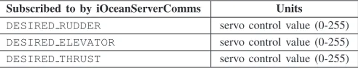
E. Primitive Control Message
The Ocean-Server $OMP message allows the backseat autonomy system to directly control the fin and propulsion settings of the vehicle. Although arguably antithetical to the backseat driver control philosophy, this enables the develop-ment of a custom dynamic controller and navigation fusion MOOS module that, in turn, facilitates control of a heavily modified Iver2 vehicle (i.e. one which no longer matches an existing frontseat control profile). The primitive control message (see Table X) requires the population of the MOOS variables shown in Table X to produce a valid $OMP message. The $OMP message follows the same timeout rules as the $OMS message.
TABLE X
PRIMITIVECONTROLMESSAGE
Subscribed to by iOceanServerComms Units
DESIRED RUDDER servo control value (0-255) DESIRED ELEVATOR servo control value (0-255) DESIRED THRUST servo control value (0-255)
IV. OPERATIONALSAFETY
This section outlines the operational safety employed in the deployment of the MAG Iver2 vehicles. Safety rules can be activated on either the frontseat or backseat payload comput-ers, with the triggering of backseat safety rules resulting in the relinquishment of vehicle control to the frontseat. The safety rules run in the IvP Helm are considered the primary safety rules with the rules run on the frontseat considered to be emergency backup in case of a backseat failure. In addition to exploring safety in software, hardware accessories are also described.
A. Backseat Safety
In addition to the IvP Helm monitoring that iOceanServer-Comms provides (see III), the use of the operating region behavior (BHV OpRegion) is used to provide the IvP Helm with a three-dimensional zone of operation and maximum mis-sion time. If the vehicle exceeds the operating region bounds or the maximum mission time, the IvP Helm commands the vehicle to a heading, depth, and speed of zero and then disengages (IVPHELM ENGAGED = DISENGAGED). After the configurable iOceanServerComms timeout has expired, control is relinquished to the frontseat computer, where the pre-programmed mission (e.g. to park the vehicle) is executed. B. Frontseat Safety
The Ocean-Server Technology frontseat control software, Underwater Vehicle Controller (or UVC), enables the operator to set a number of safety rules, including:
• Maximum depth from surface
• Minimum depth off bottom
• Maximum mission time
• Maximum dive angle over time
• Detection of no forward progress
• Detection of no upward progress when surfacing
• Detection of no downward progress when diving
• Leak detection
If an enabled safety rule triggers, then the frontseat con-troller aborts its current mission, stops processing servo ($OMS) and primitive ($OMP) commands from the backseat driver, and executes its safety return path mission, which is a series of surface waypoints previously designed to park the vehicle at a safe location on the surface where it can then be retrieved.
The frontseat safety rules should always take precedence over any backseat driver operations as the backseat autonomy is, again, only a “sensor” to the vehicle control computer.
C. Accessories
The MAG Iver2 vehicles are all equipped with Sonotronics EMT-01-2 to facilitate vehicle recovery in the event that the vehicle remains underwater beyond the mission execution time (e.g. vehicle becomes entangled or otherwise stuck).
Ocean-Server Technology, Inc. also provides a safety tow float option (patent pending), which is a small towed device capable of deploying a programmable buoyancy airbag to bring the vehicle to the surface. The MAG Iver2 vehicles will be equipped with these safety tow floats, in the near future, when completing operations that do not require the use of their towed arrays.
V. RESULTS
This section will illustrate several backseat driver mis-sions executed on the MAG Iver2 vehicle using the iO-ceanServerComms backseat driver interface module running under MOOS-IvP, one simple fixed pattern mission as well as an adaptive sampling mission. Fig. 5 and Fig. 6 show a recent hexagonal loiter mission run by the MAG Iver2 on the Charles River in Boston. The mission goal is for the vehicle to transit to the operations area, run a hexagonal loiter pattern at a one meter depth, and then return to and park at the starting location. As can be seen in the plot of the vehicle position (Fig. 5), this mission was successfully completed. The distortion in the shape of the hexagon is because of the relatively inaccurate navigation due to the use of open-loop speed control. The acquisition of a Doppler Velocity Logger (DVL) for closed-loop speed control is expected to greatly increase the navigational accuracy of the vehicle. The depth of the vehicle during the mission is shown in Fig. 6. As can be seen in the plot, the vehicle maintains its commanded one meter depth except when the periodic surface behavior forces the vehicle to surface for a GPS fix.
Fig. 5. A simple hexagonal loiter backseat mission run by the Iver2 on the Charles River. The distortion in the shape of the hexagon is because of the relatively inaccurate navigation due to the use of open-loop speed control. The acquisition of a Doppler velocity logger (DVL) for closed-loop speed control is expected to greatly increase the navigational accuracy of the vehicle.
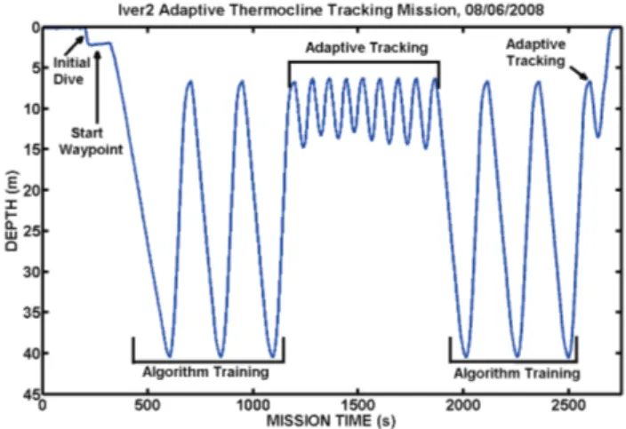
Fig. 7 shows a plot of a more complicated adaptive sampling mission. The mission goal for the vehicle is to run horizontally
Fig. 6. A plot of the Iver2 depth during the hexagonal loiter backseat mission on the Charles River. As can be seen in the plot, the vehicle maintains its commanded one meter depth except when the periodic surface behavior forces the vehicle to surface for a GPS fix.
in a fixed direction while changing its depth adaptively to try and capture the thermocline. This mission was run in80 meters of water in the Mediterranean off of Pianosa Island in August, 2008. As shown in the plot, the vehicle first samples the entire water column to gather statistics on the sound speed profile and then adaptively changes the yoyo depth to focus sampling on the thermocline which was at approximately 10 meters depth.
Fig. 7. A plot of the Iver2 depth during an an adaptive thermocline tracking mission in the Mediterranean off of Pianosa Island in August, 2008. As shown in the plot, the vehicle first samples the entire water column to gather statistics on the sound speed profile and then adaptively changes the yoyo depth to focus sampling on the thermocline which was at approximately 10 meters depth.
VI. CONCLUSION
In this paper we have described the backseat driver archi-tecture for robotic vehicles in detail and its implementation on a commercially available autonomous underwater vehicle. Although this architecture was developed for marine vehicles, it is also usable on other types of vehicles such as land or aerial robots. The driving force behind the development of this architecture was a desire for a high degree of autonomy software code reuse among different marine vehicles. In fact,
we estimate that code reuse is over90% as the vast majority of MOOS-IvP modules are reused on the Iver2, Bluefin 21, FAU Ocean Explorer, and Hydroid Remus vehicles.
One issue that needs to be addressed, and is being ad-dressed at NUWC, is the development of a standard for the backseat driver interface including message formats and interface handshake protocols. Even though all the vehicles mentioned have a backseat driver interface, each manufacturer has implemented its own message format and interface con-trol protocols. An interface standard would allow for rapid development of interface modules for new vehicles as well as increase code portability and reuse of the autonomy modules. A draft backseat driver interface standard is currently under development by the MAG and is expected to be completed by the end of 2009.
ACKNOWLEDGEMENTS
The authors would like to acknowledge the staff at Ocean Server Technology, Inc. as well as Dr. Mike Benjamin for their assistance in the development and testing of the backseat driver interface for the Iver2 vehicle.
REFERENCES
[1] M. R. Benjamin, P. M. Newman, H. Schmidt, and J. J. Leonard, “A Tour of MOOS-IvP Autonomy Software Modules,” MIT Computer Science and Artificial Intelligence Lab, Tech. Rep. MIT-CSAIL-TR-2009-009, February 2009.
[2] P. Newman, Under the Hood of the MOOS Communications API, Oxford University, 2009.
[3] M. R. Benjamin, “Interval Programming: A Multi-Objective Optimiza-tion Model for Autonomous Vehicle Control,” Ph.D. dissertaOptimiza-tion, Brown University, Providence, RI, May 2002.
[4] M. R. Benjamin and J. Curcio, “COLREGS-Based Navigation in Un-manned Marine Vehicles,” in AUV-2004, Sebasco Harbor, Maine, June 2004.
[5] M. Benjamin, J. Curcio, J. Leonard, and P. Newman, “Navigation of Unmanned Marine Vehicles in Accordance with the Rules of the Road,” in International Conference on Robotics and Automation (ICRA), Orlando, Florida, May 2006.
[6] M. Benjamin, M. Grund, and P. Newman, “Multi-objective Optimization of Sensor Quality with Efficient Marine Vehicle Task Execution,” in
International Conference on Robotics and Automation (ICRA), Orlando,
Florida, May 2006.
[7] M. R. Benjamin, D. Battle, D. P. Eickstedt, H. Schmidt, and A. Bal-asuriya, “Autonomous Control of an Autonomous Underwater Vehicle Towing a Vector Sensor Array,” in IEEE International Conference on
Robotics and Automation, Rome, Italy, April 2007, pp. 4562–4569.
[8] D. Eickstedt, M. Benjamin, H. Schmidt, and J. Leonard, “Adaptive Control of Heterogeneous Marine Sensor Platforms in an Autonomous Sensor Network,” in Proceedings of the 2006 IEEE/RSJ Int. Conf. on
Intelligent Robots and Systems, Beijing, China, October 2006.
[9] D. P. Eickstedt, M. R. Benjamin, D. Wang, J. Curcio, and H. Schmidt, “Behavior Based Adaptive Control for Autonomous Oceanographic Sampling,” in IEEE International Conference on Robotics and
Automa-tion, Rome, Italy, April 2007, pp. 4245–4250.
[10] J. DeArudda and J. Crowell, Remote Helm Guide, Ocean Server Tech-nology, Inc., 2009.