Publisher’s version / Version de l'éditeur:
Soft Matter, 2, 7, pp. 553-557, 2006-05-17
READ THESE TERMS AND CONDITIONS CAREFULLY BEFORE USING THIS WEBSITE. https://nrc-publications.canada.ca/eng/copyright
Vous avez des questions? Nous pouvons vous aider. Pour communiquer directement avec un auteur, consultez la première page de la revue dans laquelle son article a été publié afin de trouver ses coordonnées. Si vous n’arrivez pas à les repérer, communiquez avec nous à [email protected].
Questions? Contact the NRC Publications Archive team at
[email protected]. If you wish to email the authors directly, please see the first page of the publication for their contact information.
NRC Publications Archive
Archives des publications du CNRC
This publication could be one of several versions: author’s original, accepted manuscript or the publisher’s version. / La version de cette publication peut être l’une des suivantes : la version prépublication de l’auteur, la version acceptée du manuscrit ou la version de l’éditeur.
For the publisher’s version, please access the DOI link below./ Pour consulter la version de l’éditeur, utilisez le lien DOI ci-dessous.
https://doi.org/10.1039/b600936k
Access and use of this website and the material on it are subject to the Terms and Conditions set forth at
Chemical force microscopy for hot-embossing lithography release layer
characterization
Cameron, Neil S.; Ott, Arnaud; Roberge, Hélène; Veres, Teodor
https://publications-cnrc.canada.ca/fra/droits
L’accès à ce site Web et l’utilisation de son contenu sont assujettis aux conditions présentées dans le site LISEZ CES CONDITIONS ATTENTIVEMENT AVANT D’UTILISER CE SITE WEB.
NRC Publications Record / Notice d'Archives des publications de CNRC:
https://nrc-publications.canada.ca/eng/view/object/?id=311c6fc2-9859-4cab-b0ba-e6368e69a27a
https://publications-cnrc.canada.ca/fra/voir/objet/?id=311c6fc2-9859-4cab-b0ba-e6368e69a27a
Chemical force microscopy for hot-embossing lithography release layer
characterization
Neil S. Cameron,* Arnaud Ott, He´le`ne Roberge and Teodor Veres
Received 31st January 2006, Accepted 13th April 2006
First published as an Advance Article on the web 17th May 2006 DOI: 10.1039/b600936k
We employed variable temperature chemical force microscopy (VT-CFM) using tips silanized with four different hydro- and hydrofluoroalkyl self-assembling monolayers (SAMs) interact-ing with a thin-film of poly(cyclic olefin), (PCO) to model the hot-embossing stamp-polymer interaction over a temperature range spanning the glass transition of the PCO.
Introduction
High cost, slow serial throughput and resolution issues often handicap traditional micro and nanofabrication techniques. Therefore, to meet the challenges of the microelectronics, optics, MEMS, and BioMEMS industries, researchers look to next generation lithography techniques.1Among the technologies being re-invented to this end is hot-embossing lithography (HEL), an example of NanoImprint Lithography (NIL).2–4 HEL facilitates the fabrication of miniaturized devices with several advantages: resolution on the order of polymer coil dimensions, low long-term cost, flexibility, production of copies which are the near-perfect replication of the pattern, and minimum dimensions in the sub 10 nm range. HEL is promising for optical, biological and data-storage devices as well as semiconductor integrated circuits.5
Esch et. al.6 and others have investigated the role of stamp design and geometry, showing results for embossing with orthogonal stamp features as well as for more open pyramidal structures. We have initiated a systematic study of rheological and interfacial effects for nano-imprint lithography. In HEL, a raw, textured wafer is pressed into a thermoplastic polymer heated above its Tg(Fig. 1A). As the stamp progresses into the material,
the displaced polymer is pushed into the ‘bulk’ reservoir for relatively thick films. However as the stamp motifs reach the end of the stroke, the film remaining between the stamp and the substrate may approach the tribological regime where surface effects from both the stamp and the substrate act on the highly confined polymer.7 For this non-equilibrium viscoelastic system
during the embossing and de-embossing phases, a greater under-standing of the surface interactions is required with model systems including the ‘perfluoro’ surface as described below. In the absence of release layers, significant damage to the embossed polymer, the stamp, or both is often observed as illustrated in Fig. 1B.
Measuring adhesion at the nanoscale is possible due to the development of atomic force microscopy8,9 (AFM or scanning
probe microscopy, SPM) that provides instrumentation for the relatively new field of micro and nanotribology. Interfacial processes such as adhesion, friction, scratching, wear, indentation and lubrication are now routinely investigated from the atomic-, molecular- and micro-scales.10,11In order to model the embossing process with AFM (Fig. 1C), we functionalized SPM tips with selected alkylsilanes with a varying degree of perfluorination (Fig. 1D) and then brought these tips into contact with a polymer
Industrial Materials Institute: National Research Council Canada, 75 Blvd. de Mortagne, Boucherville, Que´bec, J4B 6Y4, Canada. E-mail: [email protected]; Fax: +1 (450) 641-5105; Tel: +1 (450) 641-5168
Fig. 1 Schematic representation of the hot-embossing process (A), the effect of embossing with and without release layers (B), the SPM analogue experiment (C) and a micrograph of a silane-functionalized tip and schematic indicating the effect of tip geometry on the SAM (D).
thin-film of PCO at four temperatures: 20, 60, 80, and 100 uC. While many polymers have been routinely investigated for NIL including poly(methyl methacrylate) (PMMA), polycarbonate (PC), polystyrene (PS) and others, the poly(cyclic olefins) (PCO) and cyclic olefin copolymers (COC), are increasingly popular. Zeonor 750R is a commercial-grade, fully saturated PCO with good optical properties, high chemical resistance, acceptable thermoformability and has a relatively accessible Tg for these
VT-CFM experiments.12The temperature range was selected to
span the glass transition of the polymer (72 uC).13We measured the force required to disengage the tip from the polymer. As Bhushan describes in some detail,11 force–displacement plots
provide a deceptively simple method of determining surface adhesion. When a tip is lowered near a surface, at some critical distance, van der Waals, electrostatic or other forces overwhelm the cantilever spring constant and the tip ‘snaps-to’ the surface. The tip is lowered further to a point determined by the user and then retraction may begin. During retraction, the force is negative and adhesion maintains the tip–sample contact as the negative tensile load increases through the point of maximum adhesion to an unstable regime where the cantilever stiffness is stronger than the tip–sample interaction and the contact is broken. From the cantilever spring constant ( k) and displacement (l), one can calculate the pull-off force (see eqn 1).
F(nN) = k(N/m)*l(nm) (1)
While the pull-off force is not equal to, but rather exceeds the true adhesion force,14 the distinction is not critical for the comparative study we describe below and for simplicity, we use the terms interchangeably. The separation force in similar systems has been reported to exceed pure surface-energy derived values substantially.15 The explanation for this difference may well lie in the mechanics of viscoelastic crack healing and adhesion as discussed in some detail by Baney and Hui et al.16–18 In
compliance-controlled experiments such as ours, the coupled compliance of the cantilever will determine the deviation of the pull-off force from the force of adhesion.19Elegant displacement
controlled methods have been developed and used by others to avoid the issue.20Recent work has shown that frequency modula-tion can also be exploited to extract interacmodula-tion parameters.21,22
Hydrofluoroalkyl materials defined the interface under investi-gation. Anti-adhesive Teflon1-like monolayers are vital for the
failure-free separation of stamp and substrate. The tribological properties of physisorbed and chemisorbed perfluorosilanes have been studied with the expected conclusion that chemisorption leads to more robust SAMs.23Covalently tethered self-assembled monolayers (SAMs) have several advantages over ion-sputtered and plasma deposited PTFE-films including minimal impact on feature size and longevity.15,24–27 As well as high stability with
respect to both heat and chemical attack, saturated perfluoro-carbons offer the lowest dielectric constants and surface energies of any liquid.28Many perfluoro SAMs have been studied on a variety
of surfaces including the alkanoates on zirconia,29the silanes on silicon oxide,30–32and thiolates on gold and other coinage metals.33 Short, linear perfluoro chains tend to adopt a zig-zag (all-trans) conformation and therefore occupy a geometric cylinder whereas chains longer than 12 carbons tend to take a helical form.34The perfluorocarbons are more rigid than their comparatively flexible
hydrocarbon counterparts.35Despite their rigidity, intermolecular interactions provide for complex behaviour of fluorocarbon Langmuir monolayers36,37 and solid–solid phase transitions are observed.38Hydrofluoroalkyl chain behaviour and properties are
usually intermediate between the corresponding saturated hydro-carbon and perfluoroalkyl species.28
Very recent19F NMR studies of perfluoroalkanoate SAMs on zirconia suggest that there is no evidence of chain melting at temperatures well above the Tm of bulk materials and that
enhanced SAM mobility is a result of molecular reorientations around the long chain axis.29 This finding may be important for the understanding of anti-stiction SAM behaviour in hot-embossing where adhesion, with components both normal and parallel to the displacement, occurs over complex topology at temperatures typically ranging from 40 uC to 300 uC.
Experimental
The stamp–substrate interaction was modelled in two phases. In the first instance, individual silicon wafer pieces were functionalized with four different silanes: n-octyltrichlorosilane (OTS), 1,1,2,2,-tetrahydroperfluorooctyl-trichlorosilane (F6), 1,1,2,2,-tetrahydroperfluorodecyl-trichlorosilane (F8), and 3-(heptafluoroisopropoxy)-propyltriethoxysilane (F3). For the hydrofluorosilanes, the abbreviation refers to the number of fluorinated carbon atoms. Silicon [111] wafers (Silicon Quest International) were piranha-cleaned and placed in a Pyrex vacuum chamber. Following three atmosphere exchange cycles with nitrogen gas, silane was introduced and the chamber atmosphere pressure was reduced leading to the vapour-phase surface functionalization of anti-adhesive SAMs (see Scheme 1). Despite the very high probability of inter-silane polymerization and complex film formation,39we chose the trichlorosilanes due (i) to the availability of the hydro(fluoro)alkyl series and (ii) to normalize the experiment with respect to the silanization process to focus on the release-layer–polymer interaction. In related work using F6 as a release layer applied as above (once only) to a single
Scheme 1 Structures of the four silanes examined in this study: perfluoro-isopropoxyethylsilane (F3), 1,1,2,2-tetrahydroperfluoro-octyl-silane (F6), 1,1,2,2-tetrahydroperfluorodecyl1,1,2,2-tetrahydroperfluoro-octyl-silane (F8) and octyl1,1,2,2-tetrahydroperfluoro-octyl-silane (OTS).
stamp, we have observed several hundred embossing cycles with no substantial decrease in anti-adhesive properties.13
Static contact angle measurements were determined with 18.2 MV cm water (MilliQ) using a microsyringe with the submerged-point technique.40Preliminary adhesion measurements
were obtained between bare, used-as-received Veeco NP contact-mode tips (nominal spring constant and radius of curvature 0.58 N m21and 20–60 nm respectively) and the silanized wafers
on a Veeco NanoScope IV MultiMode AFM. The wafers were imaged to determine RMS surface roughness (Table 1).
Following the preliminary experiments to determine function-alization and AFM protocols, Veeco NP contact-mode AFM tips were O2plasma treated and silanized as described above. The tips
were characterized by FEG-SEM microscopy before and after functionalization and were determined to be free of significant physical defects. Thin-films (1 mm) of poly(cyclic olefin), Zeonor 750R, were spin-coated (Brewer CEE 100) from chlorobenzene (Aldrich) on silicon wafers. Force-curves for each of the silanized tips were determined at several temperatures spanning the glass-transition of the polymer (Tg y 72 uC). Five measurements at
each of three locations were obtained for each data point in Fig. 2. The standard deviation of measurements for each datapoint was less than 5 nN.
All supported polymer films were cleaved from one film-covered silicon wafer. AFM deflection set points were minimized to avoid significant polymer penetration and to normalize the interaction. Force-curve conditions were adapted from the Veeco Metrology Group.41 The substrate holder, substrate, polymer and tip
assembly were conditionned at 20, 60, 80 and 100 uC with several hours of equilibration before measurements were acquired at each temperature.
Results and discussion
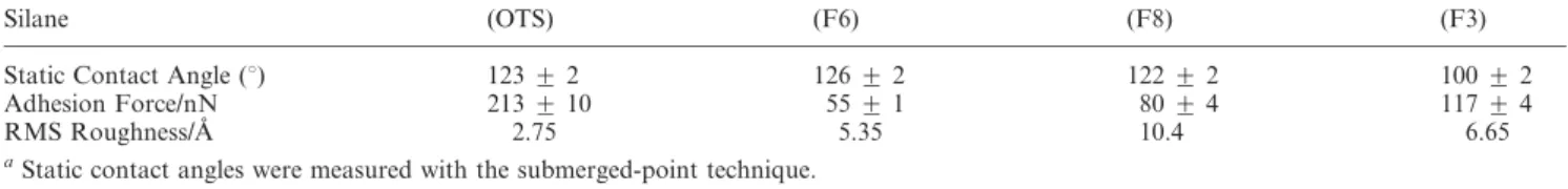
Water drop contact angles (see Table 1) on each of the silanized substrates indicated a hydrophobic surface, and the data were therefore consistent with the formation of organosilane SAMs. Contact angle measurement is a subject of some discussion40and comparison of data among devices and techniques is prone to error; however, in our hands, our device (Kernco) provided results reproducible within 2u. Of note was the comparatively high angle associated with the linear hydrofluorocarbons as compared with the lower contact angle associated with the branched hydro-fluoroalkylether. The difference was attributed to: (i) the enhanced reactivity and potentially denser coverage of the linear trichloro-silylhydrofluorocarbons as well as (ii) steric stabilization of the SAM, and (iii) the possibility of hydrogen bonding to the oxygen atom in the perfluoroisopropoxy headgroup.
The on-wafer SAMs were further characterized by chemical force microscopy (CFM)42 at room temperature as described above. The adhesive force between a used-as-received AFM tip (0.58 N m21cantilever) and each SAM was measured, the largest
force being more than 200 nN for OTS. This saturated hydrocarbon-tailed silane is frequently employed to form low-energy surfaces, however perfluorination provides even lower energy. Among the perfluorosilanes, the measured adhesion force increased from 55 nN to 117 nN as the contact angle decreased from F6 to F8 and finally to an F3 SAM (see Table 1). This result suggests that the quality and density of the SAM, which is related to the reactivity of the parent silane and its footprint at the surface, has an important effect on tip-SAM adhesion.43 The silanized
surfaces were also imaged by AFM since Schift et al.31and Fadeev
et al.39have reported on the polymerization of di- and tri-dentate silanes. We did not observe substantial surface nano-topology due to silane-silane polymerization and speculate, therefore, that our slow, low-concentration vapour-phase functionalization favoured surface pseudo self-assembly polymerization thereby reducing the possibility complex, multilayer film formation.
Since HEL involves the three-dimensional texturing of a thermoplastic polymer resin above its Tg, we employed the
variable temperature (VT) module of our multi-mode NanoScope IV to heat the substrate and SPM scanner from 20 uC to 100 uC. Multiple force curves were obtained for OTS, F6, F3 and F8-silanized AFM tips and the resulting adhesion forces are shown in Fig. 2. At 20 uC, the adhesion forces for all silanes fell within roughly 20 nN. As the temperature was raised towards Tg,
the pull-off force for the OTS and bare tips increased substantially through the transition. At temperatures below and near the Tg, the
adhesion forces for the shorter hydrofluorocarbon-decorated tips (F3 and F6) increased slightly. At 100 uC, nearly 30 uC above the PCO Tg, the adhesion forces increased for all tips since the
polymer softened, SAM mobility increased, and the tip-polymer interaction became more significant. In the temperature range
Table 1 Contact-angle and bare-tip to SAM adhesion force measurements with organosilane monolayers on silicon wafers
Silane (OTS) (F6) (F8) (F3)
Static Contact Angle (u) 123 ¡ 2 126 ¡ 2 122 ¡ 2 100 ¡ 2 Adhesion Force/nN 213 ¡ 10 55 ¡ 1 80 ¡ 4 117 ¡ 4
RMS Roughness/A˚ 2.75 5.35 10.4 6.65
aStatic contact angles were measured with the submerged-point technique.
Fig. 2 VT-CFM data for the silane-decorated SPM tip vs polymer (PCO) interaction at temperatures above and below the polymer Tg.
critical to successful de-embossing with this PCO (cooling from
Tembto Tde-emb), the data may be divided into two groups: the
non-hydrofluorinated tips (OTS and bare) and the short-chain hydrofluorinated tips (F3 and F6). Curiously, the longer-chain hydrofluorinated tip (F8) exhibits cross-over behaviour above and below Tg.
Roughness data (Table 1) and VT-CFM data suggest that the SAM coverage for the longest-chain hydrofluorosilane was imperfect, perhaps due to the lower relative availability of the silane headgroup as a result of steric hindrance during function-alization. Lower vapour-phase silane concentration for this highest-boiling silane may have also been a contributing factor, though long reaction times (several hours), reduced pressure and elevated temperature were employed to minimize this source of error. It is possible that this SAM undergoes a phase transition at or near 80 uC where there is a discontinuity in the VT adhesion force curve.
As compared with the hydrofluoroalkylsilanes, the alkylsilane indicated a strong interaction with the polymer thin-film. We have treated similar systems where brushes are in contact with polymer matrices in terms of x, the interaction parameter.44Given that an OTS brush presents as a saturated hydrocarbon surface and the polymer substrate is also a saturated hydrocarbon, x is favourable and it is unsurprising that the highest adhesion forces were measured for this system. Indeed the conditions were not unfavourable for a polymer ‘weld’. The bare, as-received tip also adhered relatively well to the PCO film above the PCO Tg,
presumably due to its relatively high surface energy.
As we routinely observe empirically with HEL, the adhesion forces measured quantitatively for the fluoroalkylsilanes indicated far better release properties, however the results require some interpretation. Based on the evidence in Table 1 for SAM quality, one might expect that F6-silanized tips would provide the lowest adhesion force. We observe instead that the lowest force corresponded to the F3-tip. We suggest that this may be due to the comparatively flexible perfluoroisopropoxy headgroup of this silane, which presents two perfluoromethyl groups per tethered silane so that even if the tether density of this silane is not as high as the F6 and F8 silanes on a flat surface, the local effect is much greater. Furthermore, the flexible ether linkage may have an important role to play in light of the stiffer fluoroalkyl species which appear to be not appreciably mobile even above their bulk melt temperature and are dominated by about-axis rotation.29
Finally, whereas the data in Table 1 were determined for silanized flat surfaces, the VT-CFM data were derived from functionalized AFM tips where the interaction is limited to the tip point. Since the steric hindrance to brush formation is substantially reduced with this geometry45it is probable that the actual footprint per F3 silane molecule is somewhat reduced as shown schemati-cally in Fig. 1D.
Conclusions
HEL is a promising alternative micro- and nanofabrication technique with the capacity to replicate sub 10 nm features, but high throughput, low-cost, and high-yield depends on appropriate stamp design, substrate selection, embossing parameters and is critically dependent on interfacial interactions during the emboss-ing stroke and de-embossemboss-ing process. We routinely replicate lines
and posts with maximum dimensions from several cm to 50 nm using stamps that have been F6 silanized. These stamps usually provide more than 100 embossing cycles before adhesion and breakage becomes an issue. The most common challenge we observe with the technique is adhesion between the stamp and the substrate, hence this study of the nature of release-layer interactions by VT-CFM.
Here we have reported: (i) appropriate chemistry for the silanization of silicon wafer substrates verified by contact angle measurements; (ii) a model system to characterize the wafer–silane interface where an as-received SPM tip was brought into contact with a functionalized wafer and pull-off forces were measured; (iii) characterization of the silane–polymer interface where silanized SPM tips were employed to measure pull-off forces from a thermoplastic polymer film above and below the polymer glass transition temperature.
The results suggest that release agents should be chosen as a function of the topology they are to functionalize. Perfluoroisopropoxy groups are well suited to features with high curvature and n-alkyl perfluorosilanes are apparently better adapted to planar surfaces. Furthermore, the data suggest that even shorter-chain silanes may provide better release layers since the silane footprint is reduced and the resulting SAM may have fewer defects.
The longest chain investigated, a 1,1,2,2-tetrahydroperfluoro-decyl silane suggested interesting adhesive behaviour below the Tg
of the PCO with adhesion-force cross-over as discussed above. The challenges inherent in measuring nano-adhesion at elevated temperatures require that ongoing and future work will compare results from other VT-CFM instruments to further characterize and understand the effect of AFM tip functionalization and the tip-polymer interactions above the polymer Tgas a model system
for hot embossing lithography.
Acknowledgements
Some of the preliminary work was performed at the Cornell Nanofabrication Facility (a member of the National Nanofabrication Users Network) which is supported by the National Science Foundation under Grant ECS-9731293, its users, Cornell University and Industrial Affiliates. The authors are also grateful for collaborations with Quantiscript Inc. and Micralyne Inc, which contribute to the context for this study. NSC is particularly grateful for helpful discussions and useful interactions with Prof. L. Cuccia (Concordia University, Montreal), Dr. G. Cross (Trinity College, Dublin), Dr. M. Geissler (NRC) and our reviewers who provided many constructive comments.
Notes and references
1 B. D. Gates, Q. Xu, M. Stewart, D. Ryan, C. G. Willson and G. M. Whitesides, Chem. Rev., 2005, 105, 1171–1196.
2 S. Y. Chou, P. R. Krauss and P. J. Renstrom, Appl. Phys. Lett., 1995, 67, 3114.
3 http://public.itrs.net.
4 H.-C. Scheer and H. Schultz, Microelectron. Eng., 2001, 56, 311–332. 5 H. Luesebrink, T. Glinsner, S. C. Jakeway, H. J. Crabtree,
N. S. Cameron, H. Roberge and T. Veres, J. Nanosci. Nanotechnol., 2005, 5, 864–868.
6 M. Esch, S. Kapur, G. Irizarry and V. Genova, Lab Chip, 2003, 3, 121–127.
7 G. Luengo, F.-J. Schmitt, R. Hill and J. Israelachvili, Macromolecules, 1997, 30, 2482–2494.
8 G. Binnig, C. F. Quate and C. Gerber, Phys. Rev. Lett., 1986, 56, 930–933.
9 N. A. Burnham and R. J. Colton, J. Vac. Sci. Technol., A , 1989, 7, 2906.
10 B. Gotsmann and U. Du¨rig, Langmuir, 2004, 20, 1495–1500. 11 Springer Handbook of Nanotechnology, ed. B. BhushanSpringer-Verlag,
New York, 2004.
12 http://www.zeonchemicals.com/.
13 N. S. Cameron, H. Roberge, T. Veres, S. C. Jakeway and H. J. Crabtree,
Lab Chip, 2006, DOI: 10.1039/b600584e.
14 Bhushan describes in detail how the pull-off occurs when the spring constant exceeds rather than equals the force of adhesion.
15 J. Taniguchi, T. Kawasaki, Y. Tokano, Y. Kogo, L. Miyamoto, M. Komuro, H. Hiroshima, N. Sakai and K. Tada, Jpn. J. Appl. Phys., 2002, 41, 4194–4197.
16 J. M. Baney and C.-Y. Hui, J. Appl. Phys., 1999, 86, 4232–4241. 17 J. M. Baney and C.-Y. Hui, Langmuir, 2001, 17, 681–687.
18 C.-Y. Hui, Y. Y. Lin and J. M. Baney, J. Polym. Sci., Part B: Polym.
Phys., 2000, 38, 1485–1495.
19 While it is tempting to refer to this experiment as ‘load-controlled’, since the cantilever and piezo are coupled in this force range, compliance-control has been suggested as a more appropriate term.
20 S. P. Jarvis, A. Oral, T. P. Weihs and J. B. Pethica, Rev. Sci. Instrum., 1993, 64, 3515.
21 M. A. Lantz, H. J. Hug, R. Hoffman, P. J. A. van Schendel, P. Kappenberger, S. Martin, A. Baratoff and H.-J. Gu¨ntherodt, Science, 2001, 291, 2580.
22 J. E. Sader and S. P. Jarvis, App. Phys. Lett., 2004, 84, 1801–1803. 23 C. D. Lorentz, M. E. Chandross, G. S. Grest, M. J. Stevens and
E. B. Webb III, Langmuir, 2005, 21, 11744.
24 M. M. Alkaisi, R. J. Blaikie and S. J. McNab, Microelectr. Eng., 2001, 57, 367–373.
25 K. Gyu Man, K. Beomjoon, M. Liebau, J. Huskens, D. N. Reinhoudt and J. Brugger, Journal of Microelectromechanical Systems, 2002, 11, 175–181.
26 Y. Hirai, S. Yoshida, A. Okamoto, Y. Tanaka, M. Endo, S. Irie, H. Nakagawa and M. Sasago, Journal of Photopolymer Science and
Technology, 2001, 14, 457–462.
27 B. J. Kim, Microelectron. Eng., 2001, 57–58, 755–760.
28 B. E. Smart, in Chemistry of Organic Fluorine Compoiunds II: A
Critical Review, ed. M. Hudlicky and A. E. Pavlath, 1995, vol. 187,
pp. 979–1010.
29 L. Reven and S. Pawsey, Langmuir, 2006, 22, 1055–1062.
30 S. R. Wasserman, G. M. Whitesides, I. M. Tidswell, B. M. Ocko, P. S. Pershan and J. D. Axe, J. Am. Chem. Soc., 1989, 111, 5852–5861. 31 H. Schift, S. Saxer, S.-G. Park, C. Padeste, U. Pieles and J. Gobrecht,
Nanotechnology, 2005, 16, S171–S175.
32 J. Genzer, K. Efimenko and D. A. Fischer, Langmuir, 2002, 18, 9307–9311.
33 C. A. Alves and M. D. Porter, Langmuir, 1993, 9, 3507–3512. 34 G. Knochenhauer, J. Reiche, L. Brehmer, T. Barberka, M. Woolley,
R. Tredgold and P. Hodge, J. Chem. Soc., Chem. Commun., 1995, 16, 1619–1620.
35 M. Sprik, U. Ro¨thlisberger and M. L. Klein, J. Phys. Chem. B, 1997, 101, 2745–2749.
36 M. E. Schmidt, S. Shin and S. A. Rice, J. Phys. Chem., 1996, 104, 2101–2114.
37 M. E. Schmidt, S. Shin and S. A. Rice, J. Chem. Phys., 1996, 104, 2114–2123.
38 T. Albrecht, H. Elben, R. Jaeger, M. Kimmig, R. Steiner, G. Strobt, B. Stu¨hn, H. Schwickert and C. Ritter, J. Chem. Phys., 1991, 95, 2807–2816.
39 A. Y. Fadeev and T. J. McCarthy, Langmuir, 2000, 16, 7268–7274. 40 A. Ulman, An Introduction to Ultrathin Organic Films: From
Langmuir-Blodgett to Self-Assembly, Academic Press, New York, 1997.
41 MultiMode SPM ver 4.31ce Instrument Manual: Digital Instruments Metrology Group (Veeco), Chapter 11, 1999.
42 C. D. Frisbie, L. F. Rozsnyai, A. Noy, M. S. Wrighton and C. M. Lieber,
Science, 1994, 265, 2071–2074.
43 It should be noted that the absolute adhesion force values are subject to some interpretation due to the nominal spring constant of the cantilevers and the effect of temperature on the scanner head, however all efforts were made to ensure that the results are self-consistent as all tips were taken from the same wafer and the experimental conditions were held constant between samples. Measurements were repeatable within 5%. We did not observe significant variability in the radii of curvature among the tips we employed.
44 M. K. Corbierre, N. S. Cameron, M. Sutton, K. Laaziri and R. B. Lennox, Langmuir, 2005, 21, 6063–6072.
45 M. K. Corbierre, N. S. Cameron and R. B. Lennox, Langmuir, 2004, 20, 2867–2873.