Publisher’s version / Version de l'éditeur:
Lighting Research and Technology, 39, June 2, pp. 123-145, 2007-06-01
READ THESE TERMS AND CONDITIONS CAREFULLY BEFORE USING THIS WEBSITE. https://nrc-publications.canada.ca/eng/copyright
Vous avez des questions? Nous pouvons vous aider. Pour communiquer directement avec un auteur, consultez la
première page de la revue dans laquelle son article a été publié afin de trouver ses coordonnées. Si vous n’arrivez pas à les repérer, communiquez avec nous à [email protected].
Questions? Contact the NRC Publications Archive team at
[email protected]. If you wish to email the authors directly, please see the first page of the publication for their contact information.
NRC Publications Archive
Archives des publications du CNRC
This publication could be one of several versions: author’s original, accepted manuscript or the publisher’s version. / La version de cette publication peut être l’une des suivantes : la version prépublication de l’auteur, la version acceptée du manuscrit ou la version de l’éditeur.
For the publisher’s version, please access the DOI link below./ Pour consulter la version de l’éditeur, utilisez le lien DOI ci-dessous.
https://doi.org/10.1177/1365782806072671
Access and use of this website and the material on it are subject to the Terms and Conditions set forth at
Optical models of complex fenestration systems
Laouadi, A.; Parekh, A.
https://publications-cnrc.canada.ca/fra/droits
L’accès à ce site Web et l’utilisation de son contenu sont assujettis aux conditions présentées dans le site
LISEZ CES CONDITIONS ATTENTIVEMENT AVANT D’UTILISER CE SITE WEB.
NRC Publications Record / Notice d'Archives des publications de CNRC:
https://nrc-publications.canada.ca/eng/view/object/?id=66af615c-009f-4c95-aa33-dabc6d87ccaa https://publications-cnrc.canada.ca/fra/voir/objet/?id=66af615c-009f-4c95-aa33-dabc6d87ccaa
http://irc.nrc-cnrc.gc.ca
O p t i c a l m o d e l s o f c o m p l e x f e n e s t r a t i o n
s y s t e m s
N R C C - 4 9 5 0 8
L a o u a d i , A . ; P a r e k h , A .
A version of this document is published in / Une version de ce document se trouve dans: Lighting Research and Technology, v. 39, no. 2, June 2007, pp. 123-145
Doi: 10.1177/1365782806072671
The material in this document is covered by the provisions of the Copyright Act, by Canadian laws, policies, regulations and international agreements. Such provisions serve to identify the information source and, in specific instances, to prohibit reproduction of materials without written permission. For more information visit http://laws.justice.gc.ca/en/showtdm/cs/C-42
Les renseignements dans ce document sont protégés par la Loi sur le droit d'auteur, par les lois, les politiques et les règlements du Canada et des accords internationaux. Ces dispositions permettent d'identifier la source de l'information et, dans certains cas, d'interdire la copie de documents sans permission écrite. Pour obtenir de plus amples renseignements : http://lois.justice.gc.ca/fr/showtdm/cs/C-42
O
PTICALM
ODELS OFC
OMPLEXF
ENESTRATIONS
YSTEMSAbdelaziz Laouadi(a) and Anil Parekh(b)
(a)
Indoor Environment Research Program
Institute for Research in Construction, National Research Council Canada
1200 Montreal Road, Ottawa, Ontario, Canada, K1A 0R6
Fax: +1 613 954 3733. Tel: +1 613 990 6868. Email: [email protected]
(b)
Sustainable Buildings and Communities
CANMET Energy Technology Centre, Natural Resources Canada
580 Booth Street, 13th Floor, Ottawa, Ontario, K1A 0E4
ABSTRACT
The need for energy conservation in buildings has spurred innovations in window technologies. These products include windows combined with shading devices, and windows featuring complex glazing such as switchable glazing, diffuse glazing, translucent and transparent insulation, patterned or decorative glass, etc. Current fenestration simulation tools for energy performance product ratings do not cover complex fenestration products. This paper addresses the development of detailed calculation models to compute the optical characteristics of complex fenestration products made up of a mixture of clear and scattering glazing layers. The models take into account not only the optical properties of the individual glazing layers making up the window product, but also the haze and gloss properties of the glazing layers. Specific optical models are developed to compute the optics of a clear substrate with applied or laminated scattering film, and composite film made up of a number of homogeneous materials with known optical properties. A general optical model was also developed for screen-like glazing panes such as
insect/shading screens, roller blinds, drapery sheets, honeycomb transparent insulation and fibreglass translucent glazing.
1 Introduction
Complex fenestration systems have been increasingly introduced in the fenestration market or specified in building designs to fulfill the requirements for high building energy-efficiency, better indoor environment quality and improved building occupant safety. Complex fenestration systems (CFS) refer to any window product that incorporates a non-clear (non-specular) layer in the glazing assembly or in its attachments (e.g., shadings). Window component manufacturers have responded to the actual requirements with superior products that combine the established technologies of the advanced window products (e.g., low-e coating, spectrally selective glazing) with innovative glazing materials such as switchable (smart) glazing, translucent or transparent insulation, solar control films doped with nano-particles, patterned/fritted glass, etc. Window attachments such as shading devices are combined with the advanced clear window products to make efficient-use of daylight and reduce the unwanted solar heat gains and potential glare problem associated with the clear window product alone. This increased applications of CFS in
unmatched with appropriate performance prediction methods, which allow building designers to pre-select products prior to their installation and quantify their performance in real buildings. The optical properties of CFS comprise one of the significant factors which affect the product energy performance and the indoor environment quality aspects such as view-through, and risk of discomfort glare, and illuminance
uniformity.
Current fenestration simulation standards for energy performance ratings, such as CSA A440.2(1), NFRC 200 and 300(2,3), and ISO 15099(4) do not cover complex fenestration products owing to the limitation of the existing simulation procedures. Most of the simulation procedures for the optical performance address only clear fenestration products, with the exception of some types of shadings devices.
The prediction of the optical performance of CFS must meet two challenging tasks: (1) the optical characterization of complex glazing, and (2) the optical interaction among the glazing layers making up the window. The traditional approach, which is merely based on the optical properties (transmittance, reflectance) of glazing, is not sufficient to describe the optical performance of the complex glazing and its optical interaction with the adjacent glazing layers making up the window. The traditional approach is unable to predict the effect of complex glazing on the view-through, window luminance, and visualization of indoor objects illuminated by the window. These limitations have prompted researchers to consider a detailed optical characterization of complex glazing together with detailed optical models to predict the total optical properties of the window. The ideal approach to characterize the optical performance of complex glazing is based on the bi-directional optical property distribution functions(5-7). The latter
indicate the amount of light propagating along all possible directions after transmission or reflection. They are expressed in two-dimensional matrices for the incident and emerging solid angles. This approach brings more insight into the optical performance of the window product. It is particularly needed for daylighting calculations where the visual detail of objects is of great importance. However, for thermal
calculations or for window product ratings, this ideal approach might not be needed, particularly when weighed against its economics. The ideal approach needs a large amount of measurement data to be collected (in the order of 12 million spectral measurement points) and a sophisticated computer program to get the window product ratings(8,9).
A less detailed approach has also been used to characterise complex glazing, but without the significant loss of accuracy and insight. The transmittance and reflectance properties of a complex glazing are split into two components – (1) specular component that maintains the direction of the incident light and (2) diffuse component that deals with the scattering effect. This approach is particularly suited to thermal calculation and window product rating as it involves less measurement points than the detailed approach, previously mentioned. This approach has been adopted in the ISO 15099 standard(4) for the optical characterization of Venetian blinds, but there was no provision in the standard to calculate the total optical properties of the complex window. This approach is also implemented in the WIS program(10) together with an optical model of the window. The WIS optical model is based on the matrix method where each glazing layer is represented by 4x4 sparse matrix, and the total window matrix is obtained by multiplying the glazing layer matrices. There was no elaboration in the WIS’s user manual on how to solve the sparse window matrix, and no method to calculate the optical properties of the sub-layers making up a composite glazing layer (such as glazing with laminated or applied scattering films). The integrating-sphere measurement technique has been used to measure the specular and diffuse components of transmittance and reflectance properties of a complex glazing. The inside surface of the sphere is equipped with a light trap to exclude the specular component from the measurement. The diffuse component is therefore directly measured while the specular component is deduced from the total, which is measured without the light trap. As a matter of fact, this method may result in a significant error since the calibration constant for the total and diffuse component of the optical properties may be different. It could be more accurate if the specular and diffuse components are directly measured. Some new measurement techniques using the integrating sphere procedure were proposed to reduce the measurement error, which is usually quite large for scattering glazing(11-13). The integrating sphere measurement method has been used in a number of studies related to complex glazing. The IEA SHCP Task 18 carried out the optical measurement of a number of complex glazing including aerogel
materials(14) and translucent plastic films(15). Small and large integrating spheres were used for the measurements of the transmittance and reflectance components. The results showed that the difference between the two procedures can be as large as 10%, and the measurements for the narrow scattering films were not reliable. The European ALTSET project looked at the measurement and modeling of complex glazing, particularly transparent insulation, solar control applied films and Venetian blinds(16-18). A quasi Fresnel optical model was proposed to predict the angular dependence of the optical properties of the scattering film. The model gave good results for the total solar transmittance, but significantly over-estimated the visible transmittance. A second enhanced optical model was proposed for which the optical
constant of the film was adjusted using two ad-hoc parameters. The scattering effect of the transparent insulation was not accounted for in the optical model of the window.
2 Objectives
The aim of this work is to develop a general methodology to compute the optical performance of complex fenestration systems. The specific objectives are:
• To develop methods to calculate the overall optical performance (transmittance, reflectance , layer absorptance, haze/gloss index) of a complex fenestration product composed of multi-pane glazing. Each glazing pane may be clear, clear with an applied scattering film, scattering, fully diffuse, or opaque.
• To apply the models to a typical clear window combined with interior shading screens.
3
Optical Characterisation of Complex Fenestration Systems
A complex fenestration system is made up of a complex frame or a glazing assembly or both. In this study, we focus on fenestration with a planar complex glazing assembly. In this regard, shadings, screens or any other attachment that covers the whole fenestration surface are considered as part of the glazing assembly when treated as the regular planar panes. Although there is no formal definition of a complex glazing, for the purpose of this study, we define a complex glazing assembly as any glazing assembly that incorporates a non-specular (not fully clear) glazing pane. Included in this definition are scattering panes and any composite pane made–up of portions of clear, translucent or opaque materials or both. In the following we will present a detailed optical model to calculate the optical properties of complex glazing assemblies.
Consider a glazing assembly made up of a number of complex panes (N). Each complex pane may scatter the incident light in all directions through transmission and reflection. Light scattering is a complex phenomenon. In the context of this study, the main factors, which generate the scattering, are the surface roughness and presence of pigments or cavities within the pane medium(19). Medium pigments contribute to the diffuse scattering, whereas surface roughness may scatter light around a dominant direction (for transmittance and reflection) and back along the incidence direction. The dominant direction of reflection scattering is dictated by the average normal of the surface micro-facets. Scattering by retro-reflection occurs when the local surface normal of the micro-facets is parallel to the incident light. This process is more common on very rough surfaces. We characterize the scattering effect of a pane by the haze property. In this regard two haze properties are defined: transmission haze (ht) for the forward
scattering, and reflection haze (hr) for the backward scattering. The haze is defined as the ratio of the
scattered portion of the transmitted (or reflected) energy around the specular direction to the total transmitted (or reflected) energy(20). The transmission haze property of a transparent medium indicates
the contrast of objects when viewed through it. The reflection haze property indicates the gloss of materials when illuminated at a given direction. The gloss index is a measure of the relative specular reflectance with respect to a reference material with 100 % gloss(21). The higher the reflection haze, the lower the gloss. The transmission haze can be measured using exiting standards such as the ASTM D1003-00(20) for haze values lower than 30%, or ASTM 167-96(22) for higher haze values. The ASTM standard D523-89(21) is used to measure the gloss index. Other non-standard methods have also been used to determine the transmission and reflection haze properties, including: (1) integrating spheres to measure the diffuse and specular components of the transmittance and reflectance(14,15,17); (2)
goniometers to measure the bi-directional transmission and reflection functions(4,6,7); (3) computer ray-tracing techniques(23). However, one should bear in mind the accuracy limits of such standards and methods. It has been shown that measuring the optical properties of diffusing materials is prone to significant error under the best of circumstances(24,25). These errors are mainly due to the diffuse light escaping from the edges of the specimen, which is not accounted for in the measurement. The size and the homogeneity of the sample also contribute to the measurement error. Similarly, measuring the specular component is dependent on the size of the source and detector.
In our study, we assume that the scattered hazy component is isotropic diffuse. This assumption is, therefore, valid for ideal diffusing or specular panes. For situations such as narrow or wide scattering panes, the assumption may provide an acceptable approximation if the narrow scattering is treated as specular, and the wide scattering as isotropic diffuse. The assumption may, however, break down for highly redirecting glazing panes (e.g. panes with diffusing lenses), when the dominant specular peak is significantly off the incidence direction, or when the scattering exhibits multiple specular peaks.
Consider now a glazing pane with ρ and τ denoting the reflectance and transmittance of the beam light incident at a given angle. The specular and diffuse components of the transmitted (τbs, τbd) and reflected
(ρbs, ρbd) luminous flux are expressed as follows:
(
−)
⋅τ τ = ⋅τ = τbs 1 ht ; bd ht (1)(
−)
⋅ρ ρ = ⋅ρ = ρbs 1 hr ; bd hr (2)To determine the overall transmittance and reflectance of a glazing assembly from the known pane optical properties, we use the stack configuration and the net radiation method. This approach was also used for clear glazing assemblies(4,26). Figure 1 shows a schematic description of the stack. Each pane may have different optical properties when irradiated from the front or back surfaces. The first 1 to j -1 panes are isolated in one component with one set of optical properties. The net radiation flux transmitted through or reflected from a given stack at a given incident angle is decomposed into two components: specular and diffuse. The total transmitted and reflected fluxes of the 1-to-j stack are obtained using the flux balance at each pane surface as follows:
bs , f ,j bs , f , 1 j : 1 bs , f ,j : 1 QT QT = − ⋅τ (3) d , f ,j bd , f , 1 J : 1 bd , f ,j bs , f , 1 j : 1 bd , f ,j : 1 QT QT QT = − ⋅τ + − ⋅τ (4) bs , b , 1 j : 1 bs , f ,j bs , f , 1 j : 1 i bs , f ,j : 1 Q R QR T QR = ⋅ − + ⋅ − (5) d , b , 1 j : 1 bd , f ,j bd , b , 1 j : 1 bs , f ,j bd , f , 1 j : 1 i bd , f ,j : 1 Q R QR T QR T QR = ⋅ − + ⋅ − + ⋅ − (6)
with the component fluxes of the 1 to j-1 stack given by:
bs , b , 1 j : 1 bs , f ,j bs , f , 1 j : 1 i bs , f , 1 j : 1 Q T QR R QT − = ⋅ − + ⋅ − (7) d , b , 1 j : 1 bd , f ,j bd , b , 1 j : 1 bs , f ,j bd , f , 1 j : 1 i bd , f , 1 j : 1 Q T QR R QR R QT − = ⋅ − + ⋅ − + ⋅ − (8) bs , f ,j bs , f , 1 j : 1 bs , f ,j QT QR = − ⋅ρ (9) d , f ,j bd , f , 1 j : 1 bd , f ,j bs , f , 1 j : 1 bd , f ,j QT QT QR = − ⋅ρ + − ⋅ρ (10) where:
QR1:j,f,bs : beam-specular reflected flux of the 1 to j stack when irradiated from the front surface (W).
QR1:j,f,bd : beam-diffuse reflected flux of the 1 to j stack when irradiated from the front surface (W).
QRj,f,bs : beam-specular flux reflected from the front surface of pane j (W).
QRj,f,bd : beam-diffuse flux reflected from the front surface of pane j (W).
QT1:j,f,bs : beam-specular transmitted flux of the 1 to j stack when irradiated from the front surface (W).
QT1:j,f,bd : beam-diffuse transmitted flux of the 1 to j stack when irradiated from the front surface (W).
QT1:j-1,f,bs : beam-specular transmitted flux of the 1 to j-1 stack when irradiated from the front
surface (W).
QT1:j-1,f,bd : beam-diffuse transmitted flux of the 1 to j-1 stack when irradiated from the front surface
(W).
R1:j,f,bs : front beam-specular reflectance of the 1 to j stack (dimensionless).
R1:j,f,bd : front beam-diffuse reflectance of the 1 to j stack (dimensionless).
T1:j,f,bs : front beam-specular transmittance of the 1 to j stack (dimensionless).
T1:j,f,bd : front beam-diffuse transmittance of the 1 to j stack (dimensionless).
T1:j-1,f,bs : front beam-specular transmittance of the 1 to j-1 stack (dimensionless).
T1:j-1,f,bd : front beam-diffuse transmittance of the 1 to j-1 stack (dimensionless).
T1:j-1,b,d : back hemispherical diffuse transmittance of the 1 to j-1 stack (dimensionless).
ρj,f,bs : front beam-specular reflectance of pane j (dimensionless).
ρj,f,bd : front beam-diffuse reflectance of pane j (dimensionless).
ρj,f,d : front hemispherical diffuse reflectance of pane j (dimensionless).
τj,f,bs : front beam-specular transmittance of pane j (dimensionless).
τj,f,bd : front beam-diffuse transmittance of pane j (dimensionless).
τj,f,d : front hemispherical diffuse transmittance of pane j (dimensionless).
By solving for the fluxes QT1:j-1,f and QRj,f from equations (7) to (10), one obtains the following
relationships: i bs b j bs f j bs f j bs f j
Q
R
T
QT
, , 1 : 1 , , , , 1 : 1 , , 1 : 11
− − −=
−
ρ
⋅
(11)(
)
(
)
(
) (
)
i bs , b , 1 j : 1 bs , f ,j d , b , 1 j : 1 d , f ,j bs , b , 1 j : 1 bs , f ,j bd , f , 1 j : 1 d , b , 1 j : 1 bd , f ,j bd , b , 1 j : 1 bs , f ,j bs , f , 1 j : 1 bd , f , 1 j : 1 Q R 1 R 1 R 1 T R R T QT − − − − − − − − −ρ ⋅ ⋅ −ρ ⋅ ⋅ ρ − ⋅ + ⋅ ρ + ⋅ ρ ⋅ = (12) i bs , b , 1 j : 1 bs , f ,j bs , f ,j bs , f , 1 j : 1 bs , f ,j Q R 1 T QR − − ⋅ ρ − ρ ⋅ = (13)(
)
(
)
(
) (
)
i bs b j bs f j d b j d f j bs b j bs f j d f j bd f j bd b j d f j bs f j bd f j bs f j bd f jQ
R
R
R
T
R
T
QR
⎥
⋅
⎦
⎤
⎢
⎣
⎡
⋅
−
⋅
⋅
−
⋅
−
⋅
⋅
+
⋅
⋅
+
⋅
=
− − − − − − , , 1 : 1 , , , , 1 : 1 , , , , 1 : 1 , , , , , , 1 : 1 , , 1 : 1 , , , , , , , , 1 : 1 , ,1
1
1
ρ
ρ
ρ
ρ
ρ
ρ
ρ
(14)By substituting equations (11) to (14) in equations (3) to (6), one obtains the following overall optical properties of the glazing assembly:
bs , b , 1 j : 1 bs , f ,j bs , f ,j bs , f , 1 j : 1 bs , f ,j : 1 R 1 T T − − ⋅ ρ − τ ⋅ = (15)
(
)
(
)
(
,jf,d 1:j 1,b,d) (
,jf,bs 1:j 1,b,bs)
d , f ,j bs , b , 1 j : 1 bs , f ,j bd , f , 1 j : 1 d , b , 1 j : 1 bd , f ,j bd , b , 1 j : 1 bs , f ,j bs , f , 1 j : 1 bs , b , 1 j : 1 bs , f ,j bd , f ,j bs , f , 1 j : 1 bd , f ,j : 1 R 1 R 1 R 1 T R R T R 1 T T − − − − − − − − − ⋅ ρ − ⋅ ⋅ ρ − τ ⋅ ⎪⎭ ⎪ ⎬ ⎫ ⎪⎩ ⎪ ⎨ ⎧ ⋅ ρ − ⋅ + ⋅ ρ + ⋅ ρ ⋅ + ⋅ ρ − τ ⋅ = (16) bs , b , 1 j : 1 bs , f ,j bs , f ,j bs , b , 1 j : 1 bs , f , 1 j : 1 bs , f , 1 j : 1 bs , f ,j : 1 R 1 T T R R − − − − −ρ ⋅ ρ ⋅ ⋅ + = (17)(
)
(
)
(
,jf,d 1:j 1,b,d) (
,jf,bs 1:j 1,b,bs)
d , b , 1 j : 1 bs , b , 1 j : 1 bs , f ,j d , f ,j bd , f , 1 j : 1 bd , b , 1 j : 1 d , f ,j bs , f ,j bd , f ,j bs , f , 1 j : 1 bs , b , 1 j : 1 bs , f ,j bs , f ,j bd , b , 1 j : 1 bs , f , 1 j : 1 bd , f , 1 j : 1 bd , f ,j : 1 R 1 R 1 T R 1 T R T R 1 T T R R − − − − − − − − − − − −ρ ⋅ ⋅ −ρ ⋅ ⋅ ⎪⎭ ⎪ ⎬ ⎫ ⎪⎩ ⎪ ⎨ ⎧ ⋅ ρ − ⋅ ρ ⋅ + ⋅ ρ ⋅ ρ + ρ ⋅ + ⋅ ρ − ρ ⋅ ⋅ + = (18)Similarly, the glazing assembly optics when the light is incident from the back side (interior side) are obtained from equations (15) to (18) as follows:
bs , b , 1 j : 1 bs , f ,j bs , b ,j bs , b , 1 j : 1 bs , b ,j : 1 R 1 T T − − ⋅ ρ − τ ⋅ = (19)
(
)
(
)
(
,jf,d 1:j 1,b,d) (
,jf,bs 1:j 1,b,bs)
d , b , 1 j : 1 bs , f ,j bs , b , 1 j : 1 bd , b ,j d , f ,j bd , b , 1 j : 1 bd , f ,j bs , b , 1 j : 1 bs , b ,j bs , b , 1 j : 1 bs , f ,j bd , b , 1 j : 1 bs , b ,j bd , b ,j : 1 R 1 R 1 T R 1 R R R 1 T T − − − − − − − − ⋅ ρ − ⋅ ⋅ ρ − ⋅ ⎪⎭ ⎪ ⎬ ⎫ ⎪⎩ ⎪ ⎨ ⎧ ρ ⋅ − ⋅ τ + ρ ⋅ + ρ ⋅ ⋅ τ + ⋅ ρ − ⋅ τ = (20) bs , b , 1 j : 1 bs , f ,j bs , b , 1 j : 1 bs , f ,j bs , b ,j bs , b ,j bs , b ,j : 1 R 1 R R − − ⋅ ρ − ⋅ τ ⋅ τ + ρ = (21)(
)
(
)
(
,jf,d 1:j 1,b,d) (
,jf,bs 1:j 1,b,bs)
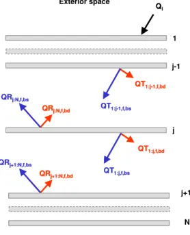
d , f ,j bs , b , 1 j : 1 bs , f ,j d , b , 1 j : 1 bd , b ,j bd , f ,j d , b , 1 j : 1 bs , b , 1 j : 1 bd , b , 1 j : 1 bs , b ,j bs , b , 1 j : 1 bs , f ,j bs , b , 1 j : 1 bd , f ,j bs , b ,j bd , b ,j bd , b ,j : 1 R 1 R 1 R 1 R R R R R 1 R R − − − − − − − − − ⋅ ρ − ⋅ ⋅ ρ − τ ⋅ ⎪⎭ ⎪ ⎬ ⎫ ⎪⎩ ⎪ ⎨ ⎧ ⋅ ρ − ⋅ ⋅ τ + ρ ⋅ ⋅ + ⋅ τ + ⋅ ρ − ⋅ τ ⋅ τ + ρ = (22)To calculate the absorptance of a given pane layer (j), we consider the stacks on either side of the pane, that is stack 1 to j-1 and stack j+1 to N, as shown in figure 2. The absorbed flux at pane j is expressed as follows: d , b ,j bd , f , N : 1 j b ,j bs , f , N : 1 j d , f ,j bd , f , 1 j : 1 f ,j bs , f , 1 j : 1 j QT QT QR QR QA = − ⋅α + − ⋅α + + ⋅α + + ⋅α (23) where:
QAj : absorbed flux by pane j (W).
QRj+1:N,f,bs: beam-specular flux reflected from the front surface of the stack j+1 to N (W).
QT1:j-1,f,bs : beam-specular flux exiting from the back surface of pane j-1 (W).
QT1:j-1,f,bd : beam-diffuse flux exiting from the back surface of pane j-1 (W).
αj,f: front beam absorptance of pane j (αj,f = 1 - τj,f - ρj,f) (dimensionless).
αj,b: back beam absorptance of pane j (αj,b = 1 - τj,b - ρj,b) (dimensionless).
αj,b,d: back hemispherical diffuse absorptance of pane j (dimensionless).
By using the net radiation method, the fluxes in equation (23) are given by the following relations for the stack sets 1 to j-1 and j to N:
bs , b , 1 j : 1 bs , f , N :j bs , f , 1 j : 1 i bs , f , 1 j : 1 Q T QR R QT − = ⋅ − + ⋅ − (24) d , b , 1 j : 1 bd , f , N : j bd , b , 1 j : 1 bs , f , N : j bd , f , 1 j : 1 i bd , f , 1 j : 1 Q T QR R QR R QT − = ⋅ − + ⋅ − + ⋅ − (25) bs , f , N : j bs , f , 1 j : 1 bs , f , N : j QT R QR = − ⋅ (26) d , f , N : j bd , f , 1 j : 1 bd , f , N : j bs , f , 1 j : 1 bd , f , N : j QT R QT R QR = − ⋅ + − ⋅ (27)
and for the stack sets 1 to j and j+1 to N:
bs , b ,j : 1 bs , f , N : 1 j bs , f ,j : 1 i bs , f ,j : 1 Q T QR R QT = ⋅ + + ⋅ (28) d , b ,j : 1 bd , f , N : 1 j bd , b ,j : 1 bs , f , N : 1 j bd , f ,j : 1 i bd , f ,j : 1 Q T QR R QR R QT = ⋅ + + ⋅ + + ⋅ (29) bs , f , N : 1 j bs , f ,j : 1 bs , f , N : 1 j QT R QR+ = ⋅ + (30) d , f , N : 1 j bd , f ,j : 1 bd , f , N : 1 j bs , f ,j : 1 bd , f , N : 1 j QT R QT R QR+ = ⋅ + + ⋅ + (31)
By solving for QRj+1:N,f from equations (28) to (31) after eliminating QT1:j,f, on obtains the following
relations: i bs , f , N : 1 j bs , b ,j : 1 bs , f , N : 1 j bs , f ,j : 1 bs , f , N , 1 j Q R R 1 R T QR + + + − ⋅ ⋅ = (32)
(
)
(
)
(
) (
)
i d , f , N : 1 j d , b ,j : 1 bs , f , N : 1 j bs , b ,j : 1 d , f , N : 1 j bd , b ,j : 1 bs , f , N : 1 j bd , f , N : 1 j bs , f ,j : 1 bs , f , N : 1 j bs , b ,j : 1 d , f , N : 1 j bd , f ,j : 1 bd , f , N : 1 j Q R R 1 R R 1 R R R R T R R 1 R T QR ⋅ ⋅ − ⋅ ⋅ − ⋅ + ⋅ + ⋅ − ⋅ = + + + + + + + + (33)Similarly, by solving for QT1:j-1,f from equations (24) to (27), and substituting the results in equation (23),
(
)
(
)
(
)(
)
(
)
(
(
) (
)
)
,jb,d d , f , N : 1 j d , b ,j : 1 bs , f , N : 1 j bs , b ,j : 1 d , f , N : 1 j bd , b ,j : 1 bs , f , N : 1 j bd , f , N : 1 j bs , f ,j : 1 bs , f , N : 1 j bs , b ,j : 1 d , f , N : 1 j bd , f ,j : 1 d , f ,j bs , b , 1 j : 1 bs , f , N : j d , f , N : j d , b , 1 j : 1 bd , f , N :j d , b , 1 j : 1 bd , b , 1 j : 1 bs , f , N :j bs , f , 1 j : 1 bs , b , 1 j : 1 bs , f , N :j bd , f , 1 j : 1 b ,j bs , f , N : 1 j bs , b ,j : 1 bs , f , N : 1 j bs , f ,j : 1 f ,j bs , b , 1 j : 1 bs , f , N : j bs , f , 1 j : 1 f ,j R R 1 R R 1 R R R R T R R 1 R T R R 1 R R 1 R R R R T R R 1 T R R 1 R T R R 1 T A α ⋅ ⋅ − ⋅ ⋅ − ⋅ + ⋅ + ⋅ − ⋅ ⋅ + α ⋅ ⋅ − ⋅ − ⋅ + ⋅ ⋅ + ⋅ − ⋅ + α ⋅ ⋅ − ⋅ + α ⋅ ⋅ − = + + + + + + + − − − − − − − + + − − (34)The foregoing equations for the total optical properties of a glazing assembly are written for any incidence angle, wavelength and light polarization. The ingredients for the evaluation of the total transmission and reflection haze are also available. The total optical properties of the glazing assembly depend on the specular and diffuse components of the optical properties of the individual glazing panes, the
hemispherical-diffuse optical properties of the individual glazing panes, and the hemispherical diffuse optical properties of the stack sets. For clear glazing panes, the laws of optics may be used to compute the optical properties of a glazing pane at any incidence angle, wavelength and light polarization state(27). For scattering panes, however, the task is not simple, and some approximations may apply. Appendix A presents a method for computing the optical properties of complex glazing panes of practical engineering applications, including applied or laminated scattering films to a clear substrate material, and multi-constituent scattering substrate materials. The applied or laminated scattering film can be continuous so that it covers the whole pane surface, or discontinuous (e.g. patterned, fritted or wired glass), covering a portion of the pane surface. Once the optical properties of the glazing panes for the beam light are known or calculated, the hemispherical diffuse optical properties of the glazing pane can be calculated using the formalism of equation (A33) of Appendix A. The hemispherical diffuse optical properties of a given stack set can be evaluated based on the hemispherical diffuse optical properties of the panes making up the stack using the forgoing equations (15) to (22) by setting the beam-specular components of the pane optical properties to zero (τbs = ρbs = 0). Appendix B presents the details of a computer algorithm for
implementation in fenestration product rating software.
4 Application
The developed optical models are implemented in the research version of SkyVision(28). The models are applied to a typical double clear window combined with an interior shading screen. First, a comparison with the predictions of the WIS computer program(10) is presented for a clear window with an interior roller blind.
4.1 Comparison with the WIS program
The current version of the WIS program handles multi-glazed windows combined with diffuse shadings and Venetian blinds. The WIS program does not, however, handle applied scattering films and screen-type glazing. Figure 3 shows a comparison between the WIS and SkyVision programs for a double clear
window combined with a diffuse interior roller blind. The optical properties of the window were taken from the WIS optical database, and they are: 6 mm clear glass with normal transmittance and reflectance equal to 0.88 and 0.08, respectively; 0.23 mm roller blind with constant diffuse transmittance and front (and back) reflectance equal to 0.23 and 0.364 (0.301), respectively. The predictions of both programs compare very well with each other, except with a slight difference at high incidence angles. This difference may be due to the fact that the WIS program uses the spectral calculation method whereas SkyVision uses the broadband calculation method.
4.2 Clear Window with Interior Shading Screen
Two types of shading screens are considered: light and dark coloured screens with material reflectance of 0.80 and 0.1, respectively. The screen fibres are assumed opaque and diffuse with thickness (diameter) equal to 1 mm. The screen is placed at the interior side of the window. Figures 4 and 5 show the profiles of the transmittance, absorptance and transmission haze of the window and screen system as a function of the incidence angle for light and dark coloured screens, respectively. Screened windows transmit light when the incidence angle is lower than a threshold value after which the transmittance becomes very small or negligible, depending on the screen reflectance. Windows with light-coloured screens usually transmit more light than those with dark-coloured screens, particularly after the threshold incidence angle. The threshold incidence angle depends on the thickness and openness factor of the screen (given by equation A50), and after which the screen behaves as a perfect diffuser (transmission haze = 1). The effect of the screen openness factor on the absorptance of the screened window is only significant when the incidence angle is lower than another threshold value of incidence angle. The latter depends on the thickness, openness factor and reflectance of the screen. Windows with dark-coloured screens absorb more light than windows with light-coloured screens due to the fact dark-coloured screens have higher absorptance. Consequently, dark–coloured screens may result in higher solar heat gains to the indoor space since a major portion of light absorption occurs at interior screens.
5 Conclusion
This paper enables the calculation of the total optical characteristics (transmittance, reflectance and layer absorptances) of complex fenestration systems made up of a mixture of clear and scattering glazing layers. The calculation models take into account not only the optical properties of the individual glazing layers making up the fenestration systems, but also the haze and gloss properties of the glazing layers. The models bring more insight into the optical performance of complex fenestration systems regarding light diffusion quality and view-through, as indicated by the total scattering haze property.
The optical models can handle any glazing assembly made up of fully clear, clear combined with applied/laminated scattering films, or scattering glazing such as shades, translucent panels, patterned glass, etc. The models are valid for any incidence angle, wavelength or light polarization state. Specific
optical models were developed to compute the optics of a clear substrate with applied or laminated scattering film, and composite film made up of a number of homogeneous materials with known optical properties. A general optical model was also developed for screen-like glazing panes such as shading screens, roller blinds, drapery sheets, honeycomb transparent insulation, and fibre-glass translucent insulation (if each fibre layer is treated as a screen-like pane). However, care should be exercised as these models have not been validated with experimental data, which we will consider in the future work.
Acknowledgments
This work was funded by the Institute for Research in Construction (IRC) of the National Research Council Canada; the CETC Buildings Group and Panel on Energy Research and Development (PERD) of the Natural Resources Canada. The authors are very thankful for their contribution.
6 References
1 CSA, CSA A440.2-04, Energy performance of windows and other fenestration systems. Canadian Standards Association; Mississauga; Ontario: Canada. 2004.
2 NFRC. NFRC 200 – 2004, Procedure for determining fenestration product solar heat gain coefficient and visible transmittance at normal incidence. National Fenestration Rating Council; Silver Spring: USA. 2004.
3 NFRC. NFRC 300 – 2004, Test method for determining the solar optical properties of glazing materials and systems. National Fenestration Rating Council; Silver Spring: USA. 2004.
4 ISO 15099. Thermal performance of windows, doors and shading devices - detailed calculations. International Standard Organisation; Geneva: Switzerland; 2003.
5 McCluney R. Suggested methodologies for determining the SHGC of complex fenestration systems for NFRC ratings. University of Central Florida; Florida: USA. 2002.
6 Andersen M., and Scartezzini J.L. Inclusion of the specular component in the assessment of bidirectional distribution functions based on digital imaging. Solar Energy. 2005; 79(2); 159-167.
7 Smith G.B., Green D.C., McCredie G., Hossain M., Swift P.D., and Luther M.B. Optical
characterisation of materials and systems for daylighting. Renewable Energy. 2001; 22; 85-90.
8 Klems J.H. A New method for predicting the solar heat gain coefficient of complex fenestration systems -I. Overview and derivation of the matrix layer calculation. ASHRAE Transactions. 1994a; 101(1); 1065-1072.
9 Klems J.H. A New method for predicting the solar heat gain coefficient of complex fenestration systems -II. Detailed description of the matrix layer calculation. ASHRAE Transactions. 1994b; 101(1); 1073-1086.
10 WinDat. WIS Reference Manual (version 3.01). Window Thermatic Network. Web site:
http://windat.ucd.ie/index.html, accessed August 2005.
11 Milburn D.I., Hollands K.G.T, and Kehl O. On measurement techniques for the spectral absorptance of glazing materials in the solar range. Solar Energy. 1998; 62(3); 163-168.
12 Polato P., Rossi G. Roucou J., Simons J. and Wilson H.R. Spectrophotometric determination of visible and solar parameters of sand blasted glass plates and translucent glass laminates. Rivista Della Stazione Sperimentale Del Vetro. 2003; 5; 5-18.
13 Montecchi M., Polato P., Geotti-Bianchini F., Rossi G. and Zinzi M. Preliminary transmittance
measurements on sand blasted glass plates using a movable integrating sphere system. Rivista Della Stazione Sperimentale Del Vetro. 2003; 3; 7-16.
14 Duer K., and Svendsen S. Monolithic silica areogel in super-insulating glazings. Solar Energy; 1998; 63(4); 259-267.
15 Chevalier B., Hutchins M.G., Maccari A., Olive F., Oversloot H., Platzer W. Polato P., Roos A., Rosenfeld J.L.j., Squire T., and K. Yoshimura. Solar energy transmittance of translucent samples: A comparison between large and small integrating sphere measurements. Solar Energy Materials and Solar Cells. 1998; 54; 197-202.
16 Rosenfeld J.L.J., Platzer W.J., Dijk H. V., and Maccari A. Modelling the thermal properties of complex glazing: Overview of recent developments. Solar Energy. 2000; 69(Suppl); 1-13.
17 Platzer W.J. The ALTSET project – Measurement of angular properties for complex glazing. European Conference; Copenhagen: Denmark. 2000.
18 Breitenbach J., Lart S., and Rosenfeld J.L.J. Optical properties and total solar energy transmittance of double glazing with solar control film. North Sun Conference, Edmonton: Canada. August 1999; 391-396.
19 ASTM E 179-96. Standard Guide for Selection of Geometric Conditions for Measurement of Reflection and Transmission Properties of Materials. ASTM International; PN: USA.
20 ASTM D 1003-00. Standard Test Method for Haze and Luminous Transmittance of Transparent Plastics. ASTM International; PN: USA.
22 ASTM E167-96. Standard Practice for Goniophotometry of Objects and Materials. ASTM International; PN: USA.
23 Andersen M., Rubin M., and Scartezzini J.L., Comparison between ray-tracing simulations and bi-directional transmission measurements on prismatic glazing. Solar Energy. 2003; 74; 157-173.
24 CIE, Radiometric and Photometric Characteristics of Materials and Their Measurement. Publication CIE No. 38 (TC-2.3), International Commission on Illumination; France. 1977.
25 Rosenfeld J.L.J., WIS Database. Data Submission Procedure for Shading and Diffusing Components, version 1. WinDat, (www.windat.org). Accessed June 2005.
26 Edward D.K., Solar absorption by each element in an absorber-cover glass array. Technical Note, Solar Energy. 1977; 19; 401-402.
27 Rubin M., Rottkay K., and Powles R., Window Optics, Solar Energy. 1998; 62; 149-161.
28 NRCC. SkyVision (version 1.2), skylight performance assessment software. National Research Council of Canada. Web site: http://irc.nrc-cnrc.gc.ca/ie/light/skyvision/, accessed August 2005.
29 Montecchi M., Nichelatti E. and Polato P. Hybrid equivalent model algorithm for the prediction of glazing angular properties. Solar Energy Materials and Solar Cells. 2002; 71; 327-342.
30 Nijnatten P.A.V., A pseudo-Fresnel approach for predicting directional optical properties of coated glazing. Thin Solid Films. 2001; 392; 282-288.
31 Roos A., Polato P., Nijnatten P.A.V., Hutchins M.G., Olive F., and Anderson C., Angular-dependent optical properties of low-e and solar control windows - simulation versus measurements. Solar Energy. 2000; 69(Suppl); 15-26.
Appendix A: Optics of a Composite Glazing Pane
A composite glazing pane refers to any glazing pane made up a substrate layer and a film or coating layer placed on the substrate surface or within its volume. Included in the definition is any composite substrate made up of a number of different materials occupying discrete volumes. Composite glazing panes are involved in a great number of fenestration applications to improve the product performance or to comply with the local code requirements (e.g. safety). Applied films, low-emmissivity coatings, and laminated, fritted or wired glass are some applications in clear window products. We have seen in Section 3 that the optics of a glazing assembly can be evaluated only if the pane optics are known a priori. The pane optics are usually measured, particularly at a normal incidence angle, or computed based on the primitive measurement data. The task might be simple for clear composite panes, as much research has addressed this issue(27,29-31). The measurements at a normal incidence angle can also be used to generate the angle dependent optical properties. However, for scattering composite panes, very little research is available to predict the composite pane optics based on the measurement data of its constituents, and there is no such model to extrapolate to other incident angles. In this section, we will present a general model to compute the optics of a composite pane based on the optical properties of its constituents. Particularly, we will address scattering films applied to, or laminated in a clear substrate material. The substrate material can be homogeneous, made up of only one material, or heterogeneous, made up of a number of homogeneous materials occupying discrete volume fractions.
A1. Applied scattering film over a clear substrate
Figure A1 shows a schematic description of an applied scattering film on the back surface of a clear plain substrate. The applied film can also be itself a composite film made up of a number of constituents, or a number of stacked layers. The film can be continuous so it covers the whole pane surface or a
discontinuous covering only a portion of the pane surface. Examples include patterned glass, or opaque pigments uniformly distributed over or within the glass surface. We define a discontinuous film by its surface fraction with respect to the total pane surface. The optical properties of a free standing film are usually available through measurements. However, the optical performance of the film will change when it is applied to a substrate. In the following, we direct our attention to the formalism to obtain the pane optics assuming that the film optics are given. We will later shed some light on the optics of a composite film to derive some practical relationships.
The incident light on a scattering pane surface will undergo multiple beam and diffuse reflections and transmissions upon reaching and exiting the composite film medium. In the general case, we assume that the film has different optical properties when irradiated from its front (facing the incident rays) or back (facing the opposite direction of the incident rays) surface. The resulting total optical properties of the pane will therefore depend on the pane side the light is incident on. The resultant total transmitted and
reflected fluxes will be made up of two components: specular and diffuse. By using the net radiation method, the specular and diffuse components are expressed as follows:
sc , bs c , bs , f bs QT QT =τ ⋅ (A1) sc , bd c , d , f sc , bs c , bd , f bd QT QT QT =τ ⋅ +τ ⋅ (A2)
(
s)
bs,sc s i s bs r Q t 1 r QR QR = ⋅ + ⋅ − ⋅ (A3)(
)
{
s s}
d bd,sc bd t 1 r QR QR = ⋅ − ⋅ (A4) where:Qi : incident beam light flux on the pane front surface (W);
QTbs : specular component of the total transmitted light flux (W);
QTbd : diffuse component of the total transmitted light flux (W);
QTbs,sc : specular component of the transmitted light flux reaching the substrate-film interface (W);
QTbd,sc : diffuse component of the transmitted light flux reaching the substrate-film interface (W);
QRbs : specular component of the total reflected light flux (W);
QRbd : diffuse component of the total reflected light flux (W);
QRbs,sc : specular component of the reflected light flux from the substrate-film interface (W);
QRbd,sc : diffuse component of the reflected light flux from the substrate-film interface (W);
ts : transmissivity of the substrate layer (dimensionless);
rs : Fresnel reflectivity of the substrate-air interface (dimensionless);
τf,bs,c : front beam-specular transmittance of the composite film (dimensionless);
τf,bd,c : front beam-diffuse transmittance of the composite film (dimensionless);
τf,d,c : front hemispherical diffuse transmittance of the composite film (dimensionless);
{p}d : designates the hemispherical diffuse value of an optical property p (dimensionless).
By performing a radiation flux balance at the substrate-film interface, one obtains the following relationships:
(
)
bs,sc 2 s s i s s sc , bs 1 r t Q r t QR QT = − ⋅ ⋅ + ⋅ ⋅ (A5){
}
d bd,sc 2 s s sc , bd r t QR QT = ⋅ ⋅ (A6) sc , bs c , bs , f sc , bs QT QR =ρ ⋅ (A7) sc , bd c , d , f sc , bs c , bd , f sc , bd QT QT QR =ρ ⋅ +ρ ⋅ (A8) where:ρf,bs,c : front beam-specular reflectance of the composite film (dimensionless);
ρf,bd,c : front beam-diffuse reflectance of the composite film (dimensionless);
ρf,d,c : front hemispherical diffuse reflectance of the composite film (dimensionless).
After solving for the unknowns of equations (A5) to (A8), and substituting the results in equations (A1) to (A4), one obtains the following relations for the total transmittance and reflectance components:
(
)
2 s s c , bs , f c , bs , f s s bs , f t r 1 t r 1 ⋅ ⋅ ρ − τ ⋅ ⋅ − = τ (A9)(
)
{
}
{
}
⎪⎭⎪⎬⎫ ⎪⎩ ⎪ ⎨ ⎧ ⋅ ⋅ ρ − ⋅ ⋅ ρ ⋅ τ + τ ⋅ ⋅ ⋅ ρ − ⋅ − = τ d 2 s s c , d , f d 2 s s c , bd , f c , d , f c , bd , f 2 s s c , bs , f s s bd , f t r 1 t r t r 1 t r 1 (A10)(
)
2 s s c , bs , f 2 s 2 s c , bs , f s bs , f t r 1 t r 1 r ⋅ ⋅ ρ − ⋅ − ⋅ ρ + = ρ (A11)(
)
{
(
)
}
(
)
(
{
} )
d 2 s s c , d , f 2 s s c , bs , f d s s s s c , bd , f bd , f t r 1 t r 1 r 1 t t r 1 ⋅ ⋅ ρ − ⋅ ⋅ ⋅ ρ − − ⋅ ⋅ ⋅ − ⋅ ρ = ρ (A12)In a similar fashion, one obtains the following relations when the light is incident on the back surface of the pane:
(
)
2 s s c , bs , f c , bs , b s s bs , b t r 1 r 1 t ⋅ ⋅ ρ − τ ⋅ − ⋅ = τ (A13)(
)
{
}
(
)
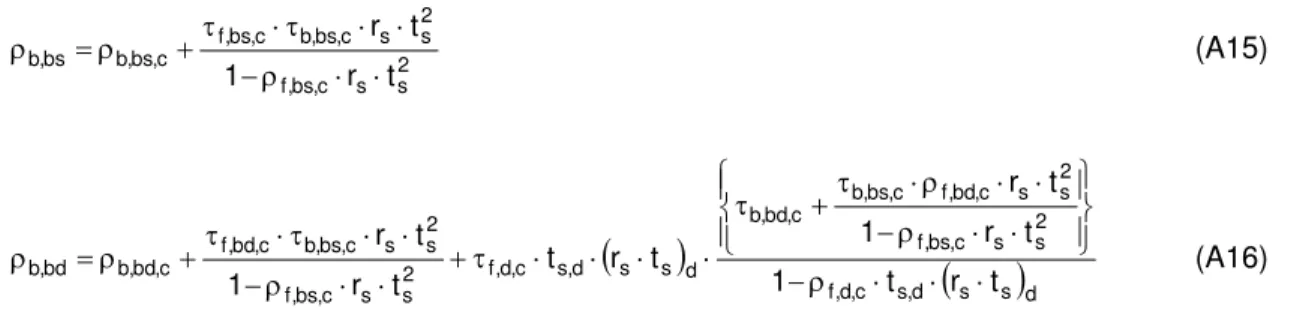
d s s d , s c , d , f 2 s s c , bs , f 2 s s c , bd , f c , bs , b c , bd , b d s s bd , b t r t 1 t r 1 t r r 1 t ⋅ ⋅ ⋅ ρ − ⎪⎭ ⎪ ⎬ ⎫ ⎪⎩ ⎪ ⎨ ⎧ ⋅ ⋅ ρ − ⋅ ⋅ ρ ⋅ τ + τ ⋅ − ⋅ = τ (A14)2 s s c , bs , f 2 s s c , bs , b c , bs , f c , bs , b bs , b t r 1 t r ⋅ ⋅ ρ − ⋅ ⋅ τ ⋅ τ + ρ = ρ (A15)
(
)
(
)
d s s d , s c , d , f 2 s s c , bs , f 2 s s c , bd , f c , bs , b c , bd , b d s s d , s c , d , f 2 s s c , bs , f 2 s s c , bs , b c , bd , f c , bd , b bd , b t r t 1 t r 1 t r t r t t r 1 t r ⋅ ⋅ ⋅ ρ − ⎪⎭ ⎪ ⎬ ⎫ ⎪⎩ ⎪ ⎨ ⎧ ⋅ ⋅ ρ − ⋅ ⋅ ρ ⋅ τ + τ ⋅ ⋅ ⋅ ⋅ τ + ⋅ ⋅ ρ − ⋅ ⋅ τ ⋅ τ + ρ = ρ (A16)Equations (A9) to (A16) show that to evaluate the total optical properties of a composite pane, the beam and hemispherical-diffuse optical properties of the substrate and film have to be known a priori.
Fortunately, these properties for a clear substrate can be evaluated based on the internal properties of the substrate material (e.g., the index of refraction) using the customary laws of optics. As for the optics of a scattering film, some approximations will be used. Methods on how to obtain these optical properties for the substrate and film will follow later.
A2. Laminated scattering film in clear substrate
Consider now a film or coating laminated between two equal-thickness clear sheets of same materials. Figure A2 shows a schematic description of this configuration. The beam light incident on the pane front surface will undergo multiple beam and diffuse reflections and transmission upon reaching and exiting the scattering film. Using the same method as above, one obtains the following relations for the beam and diffuse components of the total transmitted and reflected fluxes:
(
s)
bs,c s bs t 1 r QT QT = ⋅ − ⋅ (A17)(
)
{
s s}
d bd,c bd t 1 r QT QT = ⋅ − ⋅ (A18)(
s)
bs,c s i s bs r Q t 1 r QR QR = ⋅ + ⋅ − ⋅ (A19)(
)
{
s s}
d bd,c bd t 1 r QR QR = ⋅ − ⋅ (A20) where:QTbs,c : specular component of the transmitted light flux exiting from the back surface of the film (W);
QTbd,c : diffuse component of the transmitted light flux exiting from the back surface of the film (W);
QRbs,c : specular component of the reflected light flux from the front surface of the film (W);
QRbd,c : diffuse component of the reflected light flux from the front surface of the film (W).
By performing a radiation flux balance at the substrate-film interface, the components of the transmitted flux exiting from the back surface of the film are expressed as follows:
(
)
{
}
s bs,c 2 s c , bs , b c , bs s 2 s i s s c , bs , f c , bs t 1 r Q t r QR t r QT QT =τ ⋅ ⋅ − ⋅ + ⋅ ⋅ +ρ ⋅ ⋅ ⋅ (A21)(
)
{
}
{
}
{
s}
d bd,c 2 s c , d , b c , bs s 2 s c , bd , b c , bd d s 2 s c , d , f c , bs s 2 s i s s c , bd , f c , bd QT r t QT r t QR r t QR r t Q r 1 t QT ⋅ ⋅ ⋅ ρ + ⋅ ⋅ ⋅ ρ + ⋅ ⋅ ⋅ τ + ⋅ ⋅ + ⋅ − ⋅ ⋅ τ = (A22)Similarly, the components of the reflected flux from the front surface of the film are expressed as follows:
(
)
{
s s i s2 s bs,c}
b,bs,c s2 s bs,c c , bs , f c , bs t 1 r Q t r QR t r QT QR =ρ ⋅ ⋅ − ⋅ + ⋅ ⋅ +τ ⋅ ⋅ ⋅ (A23)(
)
{
}
{
}
{
2s s}
d bd,c c , d , b c , bs s 2 s c , bd , b c , bd d s 2 s c , d , f c , bs s 2 s i s s c , bd , f c , bd QT r t QT r t QR r t QR r t Q r 1 t QR ⋅ ⋅ ⋅ τ + ⋅ ⋅ ⋅ τ + ⋅ ⋅ ⋅ ρ + ⋅ ⋅ + ⋅ − ⋅ ⋅ ρ = (A24)By solving for the unknowns of equations (A21) to (A24), and substituting the results in equation (A17) to (A20), one obtains the following relationships for the total transmittance and reflectance components:
(
)
(
) (
)
4 s 2 s c , bs , b c , bs , f 2 s s c , bs , b 2 s s c , bs , f 2 s 2 s c , bs , f bs , f t r t r 1 t r 1 r 1 t ⋅ ⋅ τ ⋅ τ − ⋅ ⋅ ρ − ⋅ ⋅ ⋅ ρ − − ⋅ ⋅ τ = τ (A25)(
)
{
(
)
}
(
{
}
) (
)
{
} {
}
{
}
(
)
(
{
}
)
{
}
2 d 2 s s c , d , b c , d , f d 2 s s c , d , f d 2 s s c , d , b s 2 s c , bd , f d 2 s s c , d , f s 2 s c , bd , f d 2 s s c , d , f d s s s s bd , f t r t r 1 t r 1 B r t t r A r t t r 1 r 1 t r 1 t ⋅ ⋅ τ ⋅ τ − ⋅ ⋅ ρ − ⋅ ⋅ ⋅ ρ − ⋅ ⋅ + ρ ⋅ ⋅ ⋅ τ + ⋅ ⋅ + τ ⋅ ⋅ ⋅ ρ − ⋅ − ⋅ ⋅ − ⋅ = τ (A26 )(
)
{
(
)
}
(
) (
)
4 s 2 s c , bs , b c , bs , f 2 s s c , bs , b 2 s s c , bs , f 2 s s c , bs , b c , bs , f 2 s s c , bs , b c , bs , f 2 s 2 s s bs , f t r t r 1 t r 1 t r t r 1 r 1 t r ⋅ ⋅ τ ⋅ τ − ⋅ ⋅ ρ − ⋅ ⋅ ⋅ ρ − ⋅ ⋅ τ ⋅ τ + ⋅ ⋅ ρ − ⋅ ρ ⋅ − ⋅ + = ρ (A27)(
)
{
(
)
}
(
{
}
) (
)
{
} (
)
{
}
(
)
(
{
}
)
{
}
2 d 2 s s c , d , b c , d , f d 2 s s c , d , f d 2 s s c , d , b s 2 s c , bd , f d 2 s s c , d , b s 2 s c , bd , f d 2 s s c , d , b d s s s s bd , f t r t r 1 t r 1 A r t t r B r t t r 1 r 1 t r 1 t ⋅ ⋅ τ ⋅ τ − ⋅ ⋅ ρ − ⋅ ⋅ ⋅ ρ − ⋅ ⋅ + τ ⋅ ⋅ ⋅ τ + ⋅ ⋅ + ρ ⋅ ⋅ ⋅ ρ − ⋅ − ⋅ ⋅ − ⋅ = ρ (A28) with:(
)
{
}
(
) (
)
4 s 2 s c , bs , b c , bs , f 2 s s c , bs , b 2 s s c , bs , f c , bs , f c , bd , b 2 s s c , bs , b c , bs , f 2 s s c , bs , b c , bs , f c , bd , f t r t r 1 t r 1 t r t r 1 A ⋅ ⋅ τ ⋅ τ − ⋅ ⋅ ρ − ⋅ ⋅ ⋅ ρ − τ ⋅ ρ + ⋅ ⋅ τ ⋅ τ + ⋅ ⋅ ρ − ⋅ ρ ⋅ τ = (A29)(
)
{
}
(
) (
)
4 s 2 s c , bs , b c , bs , f 2 s s c , bs , b 2 s s c , bs , f c , bs , f c , bd , b 2 s s c , bs , b c , bs , f 2 s s c , bs , b c , bs , f c , bd , f t r t r 1 t r 1 t r t r 1 B ⋅ ⋅ τ ⋅ τ − ⋅ ⋅ ρ − ⋅ ⋅ ⋅ ρ − τ ⋅ τ + ⋅ ⋅ τ ⋅ τ + ⋅ ⋅ ρ − ⋅ ρ ⋅ ρ = (A30)Equations (A25) to (A28) can be evaluated only if the optical properties of the film (τc and ρc) and
substrate (rs and ts) with their hemispherical values are known or calculated. For a clear substrate, the
transmissivity and interface reflectivity are given by the laws of optics(33):
ϕ ⋅ λ ⋅ ⋅ π − = cos d k 4 s s s e t (A31)
(
)
(
)
2(
(
)
)
s 2 , s 2 2 || ,s ; with sin sin /n
sin sin r ; tan tan r ϕ= θ ϕ + θ ϕ − θ = ϕ + θ ϕ − θ = ⊥ (A32) where:
ks : extinction coefficient of the substrate (dimensionless);
ns : index of refraction of the substrate (dimensionless);
rs,|| : substrate-air interface reflectivity for the parallel polarization (dimensionless);
rs,⊥ : substrate-air interface reflectivity for the perpendicular polarization (dimensionless);
λ : wavelength of the incident light (m);
θ : light incidence angle on substrate surface (radians). The diffuse property of the product (rsp x tsq ) is calculated as follows:
{
⋅}
=π∫
[
( ) ( )
θ ⋅ θ]
⋅ θ⋅ θ 2 / 0 q s p s d q s p s t r t sin2 d r (A33)where (p, q) are ah-hoc exponents. Since the integral in equation (A33) is difficult to evaluate analytically, a numerical integration method may be used.
A3. Composite film optics
Consider a composite film made up of (m) number of discrete homogenous regions. Each homogeneous region may be made up of a number of stacked layers. The total film optics are expressed as follows:
∑
= τ ⋅ ε = τ m 1 i i, c i c (A34)∑
= ρ ⋅ ε = ρ m 1 i i, c i c (A35)where (ε) is the surface fraction of a given homogeneous region, calculated with respect to the film surface area. Similar relations can also be written for the beam and diffuse components of the film optical properties. When the film layer is clear, its optical properties can be calculated using the index of
refraction method, which is outlined in Rubin et al.(27). However, the situation may be difficult to compute the optics of a scattering film when applied to the substrate. Physical optical models based on the
scattering theory are the right approach to consider, but they are often very complicated to use in practical applications. Other simplified optical models with limited accuracy such as the two-flux radiation
scattering model may be applied to scattering films to derive the internal optical properties of a free standing film. In the absence of such physical models, one may contemplate to use some
approximations. First, one might assume that the measured optical properties of a free standing film can be directly used in the model. This might be valid if the bulk scattering of the film predominates its surface scattering. The second approximation is to apply the laws of the clear film optics to the scattering film. This approximation may hold if the film is narrow scattering(18). One should, however, be careful as this approximation is not physically-based, and it should be verified with real measurements. Rosenfeld et al.(16) found that this approximation yielded acceptable results for the solar heat gain coefficient of a double glazed window with applied solar film, but significantly over-estimated the window visible
transmittance. The third approximation applies for opaque films such as opaque frits (or wires) uniformly distributed on the substrate surface or within the substrate volume. By neglecting the reflection at the film-substrate interface (this is valid if the index of refraction of the film does significantly depart from that of the substrate), the film optics are calculated as follows:
For opaque films applied on the front substrate surface (equations A9 to A16 are used to obtain the pane optics):
(
1 film) (
1 rs)
; f,bd,c b,bd,c 0 c , bs , b c , bs , f =τ = −ε ⋅ − τ =τ = τ (A36)(
film)
s f,bd,c film bd,film film , bs film c , bs , f =ε ⋅ρ + 1−ε ⋅r ; ρ =ε ⋅ρ ρ (A37)(
1 film)
rs; b,bd,c 0 c , bs , b = −ε ⋅ ρ = ρ (A38)For opaque films totally enclosed (laminated) in the substrate volume without extending to its surface (equations A25 to A28 are used to obtain the pane optics):
0 ; 1 film f,bd,c b,bd,c c , bs , b c , bs , f =τ = −ε τ =τ = τ (A39) 0 c , bd , b c , bd , f c , bs , b c , bs , f =ρ =ρ =ρ = ρ (A40)
where εfilm is the surface fraction of the film with respect to the pane surface area, and (ρbs,film, ρbd,film) are
properties of the composite film (ρc,d, τc,d) are obtained by integration of the film beam optics (equations
A36 to A38, or equations A39 and A40) over the incidence hemisphere.
A4. Composite substrate
Consider a composite substrate made up of a number of homogeneous materials occupying discrete volumes. The amount of the radiant energy transmitted through or reflected from the composite substrate will depend on the optical properties of each homogeneous material and the optical interaction at the interface between the adjacent materials. If the interface optical interaction is neglected compared to the optical properties of the homogeneous materials, the total optical properties of the composite substrate may be obtained from those of its constituents using the arithmetic average such as in equations (A34) and (A35). However, if the interface interaction cannot be neglected, a microscopic (or macroscopic, depending on the characteristic length of the substrate medium) model, in which the structure of the composite substrate is scrutinized to come up with practical relations for the total optical properties. In this section, we consider a typical case in which the composite substrate is made up of a matrix material and a void space. Typical examples include shading screens, roller blinds, drapery sheets, perforated glazing pane, etc. Figure A3 shows a typical screen pane. The screen is made up of a number of cross-linked wires or fibres (yarns for draperies). We assume that the fibres are circular or square, and may be transparent to the incoming light. We characterize the void space by the openness factor, which is defined as the ratio of the void surface area to the total surface area of a representative volume.
By applying the radiation flux balance on the representative volume (as shown in figure A3) and limiting the specular inter-reflections within the void space to only one reflection, one obtains the following relations for the total transmitted and reflected flux components:
(
) (
)
(
)
{
f,bs,sw f,bs,sw}
i(
o)
f,bs,s o i bs Q 1 1 Q 1 QT = ⋅ε ⋅ χ+ −χ ⋅ −λ ⋅ τ +ρ + ⋅ −ε ⋅τ (A41)(
w)
i(
o)
f,bd,s w bd Q 1 F /2 Q 1 QT = ⋅ − + ⋅ −ε ⋅τ (A42)(
o)
f,bs,s i bs Q 1 QR = ⋅ −ε ⋅ρ (A43)(
1)
Q(
1 F)
/2 Q QRbd = i⋅ −εo ⋅ρf,bd,s + w⋅ − w (A44) where:Qi : incident light flux on the representative volume (W);
QTbs : beam-specular component of transmitted light flux through the representative volume (W);
QTbd : beam-diffuse component of transmitted light flux through the representative volume (W);
QRbd : beam-diffuse component of reflected light flux from the representative volume (W);
Qw : reflected light flux from the inner wall of the fibre (W);
Fw : View factor of the fibrewall surface to itself (dimensionless);
εo : openness factor of the substrate medium (dimensionless);
λ : fraction of the reflected beam light from the screen wall undergoing more than one reflection (dimensionless);
χ : fraction of the incident flux on the void surface, which is directly transmitted (without inter-reflections) (dimensionless);
τf,bs,s : beam-specular component of the transmittance of the screen material (wire) (dimensionless);
τf,bd,s : beam-diffuse component of the transmittance of the screen material (wire) (dimensionless);
ρf,bs,s : beam-specular component of the reflectance of the screen material (wire) (dimensionless);
ρf,bd,s : beam-diffuse component of the reflectance of the screen material (wire) (dimensionless);
ρf,bs,sw : beam-specular component of the reflectance of the screen material (wire) at an incidence angle
π/2-θ (dimensionless);
ρf,bd,sw : beam-diffuse component of the reflectance of the screen material (wire) at an incidence angle
π/2-θ (dimensionless).
By performing a flux balance at the fibre wall, the flux Qw is expressed as follows:
(
)
(
)
(
)
o(
)
i w sw d f sw d f sw bs f sw bs f sw bd f sw bd f wQ
F
Q
⋅
⋅
−
⋅
⋅
+
−
+
⋅
+
+
=
ε
χ
ρ
τ
ρ
τ
λ
ρ
τ
1
1
, , , , , , , , , , , , (A45)where τf,d,sw and ρf,d,sw is the hemispherical diffuse transmittance and reflectance of the screen wall
material.
By substituting equation (A45) in equations (A41) to (A44), one obtains the following relationships for the total transmittance and reflectance components:
(
o)
f,bs,s o{
(
) (
)
(
f,bs,sw f,bs,sw)
}
bs , f = 1−ε ⋅τ +ε ⋅ χ+ 1−χ ⋅1−λ ⋅ τ +ρ τ (A46)(
)
(
(
)
(
)
)
(
) (
)
2
1
1
1
1
, , , , , , , , , , , , , , , w o w sw d f sw d f sw bs f sw bs f sw bd f sw bd f s bd f o bd fF
F
−
⋅
−
⋅
⋅
⋅
+
−
+
⋅
+
+
+
⋅
−
=
ε
χ
ρ
τ
ρ
τ
λ
ρ
τ
τ
ε
τ
(A47)(
o)
f,bs,s bs , f = 1−ε ⋅ρ ρ (A48)(
)
(
(
)
(
)
)
(
) (
)
2
1
1
1
1
, , , , , , , , , , , , , , , w o w sw d f sw d f sw bs f sw bs f sw bd f sw bd f s bd f o bd fF
F
−
⋅
−
⋅
⋅
⋅
+
−
+
⋅
+
+
+
⋅
−
=
ε
χ
ρ
τ
ρ
τ
λ
ρ
τ
ρ
ε
ρ
(A49)By taking into consideration figure A3, the fractions (χ, and λ) are given by the following relationships:
(
)
(
)
⎪⎩ ⎪ ⎨ ⎧ > θ ≤ θ ⋅ ⋅ θ − = χ s s 1 -s s -1 s s d / q tan if , 0 d / q tan if , q / d tan 1 (A50)(
)
(
)
⎪⎩ ⎪ ⎨ ⎧ > θ − θ ⋅ ≤ θ = λ s s 1 -s s s s -1 d / q tan if , 1 tan q / d , 1 min( d / q tan if , 0(
)
(A51)where (θ) is the incidence angle on the screen surface, (ds) is the thickness of the fibre (or ds = π/4 times
the diameter of a circular fibre), and (qs) is the characteristic length of the void space. The characteristic
length (qs) is related to the openness factor by the following relationship:
s o o s d 1 q ε − ε = (A52)
Equations (A46) to (A49) can be evaluated if the optical properties of the screen material are available. The latter can be directly measured or deduced from the measurements of the total optical properties of the screen pane. It should be noted that the optical model of the screen pane can be used to model multi-layer screen-like glazing such as, for example, honeycomb transparent insulation, and fibre-glass
Appendix B: Computer Algorithms
This section presents a computer algorithm to compute the total optical properties of a glazing assembly from the pane optics using the formalism of section 3. Details of the algorithm follow.
For each wavelength
Pre-calculate the hemispherical diffuse optical properties of each glazing pane for the parallel and perpendicular light polarization states;
For a given incidence angle,
For each light polarisation,
Calculate the optics of all glazing panes making up the glazing assembly;
Calculate the reflectance and transmittance of the stack 1 to j (j =1 to N) as follows:
Calculate the beam optics of the stack 1 to j-1 using the recursive formulas of equations (15) to (22);
Calculate the hemispherical diffuse optics of the stack 1 to j-1, using the same recursive formulas of equations (15) to (22), but with the pane diffuse optics as inputs (set all beam-specular components to zero);
Deduce the beam optics of the stack 1 to j using equations (15) to (22);
Calculate the layer absorptance of pane j (j = 1 to N) as follows (separate loop from above):
Calculate the beam and hemispherical-diffuse optics of the stack sets: 1 to j-1, 1 to j, j to N, and j+1 to N using the recursive equations (15) to (22);
Deduce the layer absorptance from equation (34);
Average the total glazing optics over for the two polarization states;
QT1:j-1,f,bd QT1:j-1,f,bs QT1:j-1,f,bd QT1:j-1,f,bs j-1 1 j QR1:j,f,bd QR1:j,f,bs QR1:j,f,bd QR1:j,f,bs QRj,f,bd QRj,f,bs QRj,f,bd QRj,f,bs QT1:j,f,bd QT1:j,f,bs QT1:j,f,bd QT1:j,f,bs Qi Qi Interior space Exterior space
Figure 1 Stack of glazing panes for the calculation of the total transmittance and reflectance
j-1 1 j Qi Qi j+1 N QRj:N,f,bd QRj:N,f,bs QRj:N,f,bd QRj:N,f,bs Interior space Exterior space QT1:j-1,f,bd QT1:j-1,f,bs QT1:j-1,f,bd QT1:j-1,f,bs QT1:j,f,bd QT1:j,f,bs QT1:j,f,bd QT1:j,f,bs QRj+1:N,f,bd QRj+1:N,f,bs QRj+1:N,f,bd QRj+1:N,f,bs
0 0.2 0.4 0.6 0.8 1 0 10 20 30 40 50 60 70 80 9
Incidence Angle (degrees)
T ran smittan ce (o r Reflectan ce) 0
SkyVision - Front Transmittance WIS - Front Transmittance SkyVision - Front Reflectance WIS - Front Reflectance
Figure 3 Comparison with the WIS computer program
0 0.2 0.4 0.6 0.8 1 0 10 20 30 40 50 60 70 80 9
Incidence Angle (degrees)
Op tical Pro p e rty 0 Transmittance (openness = 100%) " (openness = 25%) " (openness = 5%) Absorptance (openness = 100%) " (openness = 25%) " (openness = 5%) Trans. Haze (openness = 25%) " (openness = 5%)
Figure 4 Profiles of transmittance, absorptance and transmission haze of a double clear Window with an interior light-coloured screen