Dielectric Liquid Ionization Chambers for Detecting Fast
Neutrons
by
Erin M. Boyd
B.S. Physics, Spelman College (2004)
Submitted to the Department of Nuclear Science & Engineering
in partial fulfillment of the requirements for the degree of
Master of Science
at the
MASSACHUSETTS INSTITUTE Of TECHNOLOGY
L-FVe-O1ruary
September 2007
!Doo'?
C Massachusetts Institute of Technology 2007. All rights reserved.
A uthor... ... ... " I r
Departm nt of Nucle r
, > /)9cie/ce & Engineering
September 10, 2007
Certified by
Certified by..
Accepted
by...
MASSACHuSETS INTIU OF TECHNOLOGYJUL
2 4 2008
LIBRARIES
C(
/
Richard Lanza
Senior Research Scientist
Department of Nuclear Science & Engineering
SThesis Supervisor
Dwight Williams
MLK Visiting Professor
Department of Nuclear Science & Engineering
Thesis Reader
/,
Jeffery Coderre
Chairman, Departmental Committee on Graduate Students
Department of Nuclear Science & Engineering
MRCHIVES
Dielectric Liquid Ionization Chambers for Detecting
Fast Neutrons
by
Erin Boyd
Submitted to the Department of Nuclear Science & Engineering
on September 10, 2007, in partial fulfillment of the requirements for the degree of Master of Science in Nuclear Science & Engineering
Abstract
Three ionization chambers with different geometries have been constructed and filled with dielectric liquids for detection of fast neutrons. The three dielectric liquids studied were Tetramethylsilane (TMS), Tetramethylpentane (TMP), and Isooctane, which each have intrinsic properties that make them attractive for fast neutron detection. Their electronic properties are similar to those of condensed noble gases, but they don't require cryogenic temperatures to maintain liquid phase. However, like condensed noble gases, they do require a high level of purity.
A stainless steel purification system was constructed to purify the liquids and the
purity was monitored by an ionization chamber with a 241Am source inside. The three liquid detectors were exposed to 250keV x-rays from an orthovoltage x-ray tube and neutrons (1.4-12MeV) from a 1-Ci 239Pu-Be source.
Experimental data show that an ionization chamber filled with dielectric liquid is capable of detecting fast neutrons in pulse mode. While chamber 1, chamber 2, and chamber 3 (filled with TMS) did not respond to the Pu-Be source, chamber 3 (filled with TMP and Isooctane) successfully detected the presence of neutrons. Data also show that the chambers could not detect gamma rays from giCi Co-60 and Cs-137 check sources. In addition, the chambers could detect 250 keV x-rays in current mode, but not pulse mode. These results present positive implications for the gamma-blindness of the dielectric liquids studied.
Thesis Supervisor: Dr. Richard Lanza Title: Senior Research Scientist
Acknowledgements
I would like to thank Dr. Richard Lanza for his supervision, financial and intellectual support, and patience throughout my time at MIT. He has been an enormous source of information and I have learned very much.
Many thanks go to Dr. Gordon Kohse. I honestly don't know if I could have completed this work without his unlimited support and assistance. Gordon listened to each of my ideas and helped me implement them. Words cannot express how much I appreciate his guidance.
I thank Dr. Dwight Williams for his moral support and careful reading of this thesis. I can't thank Dwight enough for flying to Boston on a Sunday morning, just to sign my thesis, and immediately flying back to Washington D.C.
Additional thanks go to MITR RPO and MIT Reactor staff for allowing me to use their laboratory space to run my experiments and to the Nuclear Science and Engineering Department for allowing me to study at MIT.
Finally, I thank the deans and staff in the Graduate Students Office. They have supported me since I arrived at MIT and I am extremely appreciative.
Contents
ABSTACT... 2 ACKNOW LEDGEMENTS ... 3 CONTENTS ... 4 LIST OF FIGURES ... 7 LIST OF TABLES... 10 CHAPTER 1 INTRODUCTION ... ... 11 1.1 Neutron Detection... ... 111.1.1 Slow Neutron Detection... 12
1.1.2 Fast Neutron Detection ... ... 13
1.2 Fast Neutron Detectors... 16
1.2.1 Scintillation Detectors... 16
1.2.2 Gas Proportional Counters... 20
1.3 Fast Neutron Detector Applications ... 21
1.3.1 Reactors... 21
1.3.2 Fast Neutron Resonance Radiography ... 22
1.4 Fast Neutron Detector Limitations... ... ... 22
1.4.1 Recombination...22
1.4.2 Multiple Elastic Scattering Events... 23
1.4.3 Spatial Resolution... 23
1.4.4 Gamma Interactions ... 24
1.5 Room Temperature Liquid Ionization Chamber for Fast Neutron Detection... 27
1.5.1 Chamber Geometry... . 27
1.5.2 Modes of Operation... 31
1.5.3 Fast Neutron Detection Applicability.... ... ... 33
1.6 Scope of this Study... 34
CHAPTER 2 ROOM TEMPERATURE DIELECTRIC LIQUID
IONIZATION CHAMBER... 36
2.1 Dielectric Liquids ... ... 36
2.1.1 Benefits of using Dielectric Liquids to Detect Fast Neutrons... . 37
2.1.2 Safety Information ... 40
2.1.3 Purity Limitations and Monitoring... 41
2.2 Purification System Design ... 42
2.3 Liquid Ionization Chamber Designs ... 43
2.3.1 Chamber 1 ... 44 2.3.2 Chamber 2 ... ... 45 2.3.3 Chamber 3 ... ... 47 2.4 E lectronics ... ... 48 2.4.1 Electronic Noise ... ... 50 2.5 T heory ... ... 50
2.5.1 Cross Section Analysis ... 50
2.5.2 Pulse Height Analysis ... 53
2.5.3 Intrinsic Efficiency... 54
2.5.4 Absolute Efficiency... 57
CHAPTER 3 PURIFICATION AND MONITORING ... 60
3.1 Purification Facility ... ... 60
3.2 Cleaning Purification System ... ... 61
3.3 Cleaning the Chamber ... ... 61
3.4 Purification Process ... 62
3.4.1 Difficulties... 63
3.5 Monitoring Purity ... 63
3.5.1 Time-Of-Flight Principle ... ... 63
3.5.2 Signal Height Comparison.... ... ... ... 65
3.5.3 Conductivity.... ... ... ... 65
3.5.4 Liquid Purity... 66
CHAPTER 4 EXPERIMENTAL WORK ... 73
4.1.1 X-ray Source ... 74
4.1.2 Gas-Filled Ionization Chamber Experiments ... 75
4.1.3 Summary of Gas-Filled Ion Chamber X-Ray Experiments ... 79
4.1.4 Dielectric Liquid Filled Ionization Chamber X-Ray Experiments... 80
4.1.5 Summary of Dielectric Liquid X-Ray Experiments ... 85
4.1 Fast Neutron Experiments ... 86
4.2.1 Neutron Source ... 86
4.2.2 Experimental Setup... ... ... 88
4.2.3 Summary of Neutron Exposure Experiments ... ... 94
CHAPTER 5 CONCLUSION ... 95
5.1 Project Successes ... 95
5.2 Project Shortcomings ... 96
5.3 Suggestions for Future Work ... 97
REFERENCES ... 99
APPENDIX ... 101
A. Pulse Height Calculations... ... 101
B. Sensitive Volume Calculations ... 102
C. Electric Field Calculations... 104
D. Solid Angle Calculations ... 106
E. Calculated Efficiency Values... ... 108
List of Figures
Figure 1.1 Cross Section Energy Dependence for Popular
Neutron-Induced Reactions ... 14
Figure 1.2 100keV electron and 500keV neutron pulse ... ... 25
Figure 1.3 Graph formulated from pulse height/shape analysis ... 25
Figure 1.4 Risetime vs. pulse height plot ... 26
Figure 1.5 Basic parallel plate ionization chamber and electronic components ... 28
Figure 1.6 Electric field map for oppositely charge parallel plates ... 29
Figure 1.7 Basic cylindrical ionization chamber drawing ... 29
Figure 1.8 Illustration of field lines for oppositely charged cylindrical electrodes ... 30
Figure 1.9 Cross-section of oppositely charged spherical conductors... 31
Figure 1.10 Circuit of ionization chamber operated in pulse mode ... 32
Figure 1.11 Circuit of ionization chamber operated in current mode ... ... 33
Figure 2.1 Incoherent scattering cross sections for TMS ... 37
Figure 2.2 Incoherent scattering cross sections for TMP ... . 38
Figure 2.3 Incoherent scattering cross sections for Isooctane ... 38
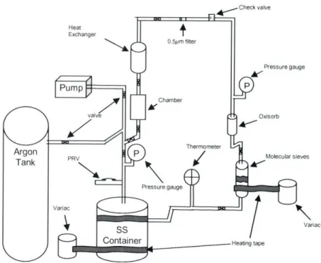
Figure 2.4 Schematic drawing of dielectric liquid purification system ... 43
Figure 2.5 Photograph of dielectric liquid purification system ... 43
Figure 2.6 Photograph of chamber 1 prior to assembly ... 44
Figure 2.7 Photograph of chamber 1 after assembly ... 44
Figure 2.8 Cross-section view of chamber 1 ... 45
Figure 2.9 Cross-section view of cylindrical ionization chamber (chamber 2) ... 46
Figure 2.10 Photograph of chamber 2 parts prior to assembly ... 46
Figure 2.11 Photograph of chamber 2 after assembly ... 46
Figure 2.12 Cross-section view of chamber 3 ... 47
Figure 2.13 Photograph of chamber 3 parts ... 48
Figure 2.14 Photograph of chamber 3 assembled ... 48
Figure 2.15 Schematic drawing of electronics ... 49
Figure 2.16 Photograph of electronics ... 49
Figure 2.18 Graph of cross sections data for dominant reactions in Isooctane ... 52
Figure 2.19 Graph of cross sections data for dominant reactions in TMP ... 52
Figure 2.20 Calculated intrinsic detection efficiency for various neutron energies for cham ber 1 ... 56
Figure 2.21 Calculated intrinsic detection efficiency for various neutron energies for cham ber 2 ... 56
Figure 2.22 Calculated intrinsic detection efficiency for various neutron energies for cham ber 3 ... 57
Figure 2.23 Calculated absolute detection efficiency for various neutron energies for cham ber 1 ... 58
Figure 2.24 Calculated absolute detection efficiency for various neutron energies for cham ber 2 ... 59
Figure 2.25 Calculated absolute detection efficiency for various neutron energies for cham ber 3 ... 59
Figure 3.1 Output pulse shape from an ion chamber for various time constants... 64
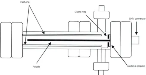
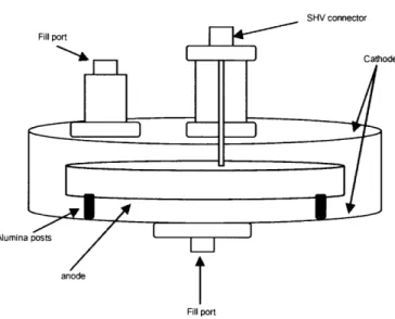
Figure 3.2 Illustration of the purity monitor design ... ... 67
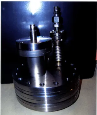
Figure 3.3 Photograph of purity monitor ... 68
Figure 3.4 Measured cathode and anode signals from purity monitor filled with Isooctane ... ... 69
Figure 3.5 Measured cathode and anode signals from purity monitor filled w ith T M S ... ... 70
Figure 3.6 Measured cathode and anode signals from purity monitor filled with TMP ... ... ... ... 71
Figure 4.1 Illustration of setup for Chamber 1 x-ray experiment ... ... 75
Figure 4.2 Ionization current against electric field strength for x-rays in P-10 (chamber 1)... 76
Figure 4.3 General current-voltage relationship of an ion chamber ... 76
Figure 4.4 Illustration of setup for Chamber 2 x-ray experiment ... ... 77
Figure 4.5 Saturation curve for x-rays in P-10 (chamber 2) ... 78
Figure 4.6 Illustration of setup for Chamber 3 x-ray experiment ... ... 79
Figure 4.8 Ionization curve for x-rays in Isooctane (chamber 2) ... ... 81
Figure 4.9 Ionization curve for x-rays in TMP (chamber 2) ... 81
Figure 4.10 Ionization curve for x-rays in TMS (chamber 2) ... 82
Figure 4.11 Ionization curve for x-rays in Isooctane (chamber 3) ... 83
Figure 4.12 Ionization curve for x-rays in TMP (chamber 3) ... 83
Figure 4.13 Ionization curve for x-rays in TMS (chamber 3) ... ... 84
Figure 4.14 Ionization current for indicated liquids at various electric fields (chamber 2) ... ... 84
Figure 4.15 Ionization current for indicated liquids at various electric fields (cham ber 3) ... 85
Figure 4.16 Double-walled construction of a Pu-Be source ... 87
Figure 4.17 Energy spectrum of neutrons from a 1-Ci 239PuBe source ... 88
Figure 4.18 Plot of averaged neutron counts against applied voltage (Isooctane) ... 92
List of Tables
Table 1.1 Neutron-induced nuclear reactions for slow neutron detection ... 13
Table 1.2 List of well known organic plastic scintillators ... 18
Table 1.3 List of well known organic liquid scintillators ... 20
Table 2.1 List of dielectric liquids and their important properties ... 36
Table 4.1 Voltage and beam current settings with appropriate filters ... . 74
Table 4.2 List of 239Pu-Be source properties ... 86
Table 4.3 Counts obtained for Chamber 2 filled with Isooctane at various applied voltages ... ... 90
Table 4.4 Counts obtained for Chamber 2 filled with TMS at various applied voltages ... ... 90
Table 4.5 Counts obtained for Chamber 2 filled with TMP at various applied voltages ... 90
Table 4.6 Experimental Absolute and Intrinsic Efficiency values for Chamber 3 filled with Isooctane... 93
Table 4.7 Experimental Absolute and Intrinsic Efficiency values for Chamber 3 filled with TMP... 93
Table E. 1 Calculated intrinsic efficiencies ... 108
Table E.2 Calculated absolute efficiencies ... 108
Table F. 1 Observation 1: Chamber 3 filled with Isooctane ... 109
Table F.2 Observation 2: Chamber 3 filled with Isooctane ... 109
Table F.3 Observation 3: Chamber 3 filled with Isooctane ... 110
Table F.4 Observation 1: Chamber 3 filled with TMP ... 110
Table F.5 Observation 2: Chamber 3 filled with TMP ... 111
Chapter 1
Introduction
Fast neutrons have proven to be extremely useful in various facets of research and industry. Two necessary processes used in neutron applications are neutron production and detection. While fast neutron production has been successfully accomplished by different methods, neutron detection has not been easy to master. The major challenges encountered with neutron detection are high energy photon background noise, neutron neutrality, recombination, multiple events, and spatial resolution to name a few. These factors cause the efficiencies of modem-day fast neutron detectors to be extremely low.
The type of neutron detector that should be used for a given application depends on factors such as the initial neutron energy and the goals of the specific neutron application. Depending on the neutron application, the ability to count neutrons in the vicinity of the detector may be sufficient. However, if the detector is required to measure the initial energy of the neutrons, the detector design becomes more complex. Regardless of what function the detector performs, its effectiveness is highly dependent upon its efficiency. Thus, there is a clear need for higher efficiency neutron detectors.
This thesis examines the design and operation of a dielectric liquid ionization chamber which is used for detecting neutrons with a higher efficiency than existing neutron detectors.
1.1 Neutron Detection
Neutron detection is performed through indirect methods because, like photons, neutrons are uncharged particles. Due to the charge neutrality of neutrons, they do not interact with the electrons of an atom in matter. Rather, they interact with the nucleus of that atom. In other words, they do not respond to Coulomb force. Charged particles,
such as protons, alphas, betas, etc. are the result of such nuclear interactions. The electrical signals generated from these charged particles are processed for detection. Direct detection of the charged particles, in turn, indirectly detects the neutrons.
The technique used for neutron detection is dependent upon the neutron energy because the cross section for neutron interactions in materials is a function of neutron energy. For neutrons that have energies below 0.5eV, neutron-induced nuclear reactions are the most common interaction for detection purposes. As the neutron energy increases, scattering becomes a more dominant interaction. Elastic scattering is the most probable neutron interaction at neutron energies above 0.5eV, but when the neutron energy is sufficiently high, inelastic scattering with nuclei may occur.
1.1.1 Slow Neutron Detection
Slow neutrons are defined as neutrons with kinetic energy less than 0.5eV. At these energies, the significant neutron interactions are neutron-induced nuclear reactions and neutron elastic scattering with target nuclei. The most common means of detecting slow neutrons are based on neutron-induced nuclear reactions because very little energy can be transferred to the target nuclei during an elastic collision caused by a slow neutron.
Neutron-Induced Nuclear Reactions
Neutron-induced nuclear reactions that are employed for detection create secondary radiation that has enough energy to be directly detected. In order for these particular reactions to occur, the Q-values for these reactions must be positive. The
Q-value is the energy equivalent of the difference in atomic masses between the reactants and products, all in their nuclear ground states. Q-value is calculated using equation 1.1.
Q-
[(M,+M2)-(M
,, +M2,)]c2 Eq. 1.1where M1 is the incoming particle, M2 is the target nucleus, M1, is the outgoing particle and M2, is the recoil nucleus.
The Q-values of the reactions, rather than the energy of the incoming slow neutron, determine the kinetic energy of the reaction products. This is because the Q-value is typically sufficiently greater than that of the incoming neutron.
The most probable reaction that occurs from neutron-induced nuclear reactions is radiative capture (n, y). This reaction is not often used to detect neutrons because, like neutrons, it is also difficult to detect gamma rays due to their neutrality. More common reactions used for neutron detection are (n, a), (n, p), and (n, fission fragment). Each of these common neutron detection reactions results in heavy charged particles. The three most popular reactions and their Q-values can be found in table 1.1.
Table 1.1 Neutron-induced nuclear reactions for slow neutron detection
Reaction Name Reaction Q-value
loB(n,a) lB+ ±no - 7Li3 + 40 2.792 MeV (ground state)
loB5 + 'n ) 7Li* + 3 4o2 2.310 MeV (excited state)
6Li(n,a) Li3+ 'no - 3HI + 4C 4.78 MeV
He(n,p) He2 + no - 3H1 + pli .764 MeV
*excited state
Neutron-induced fission reactions, although not listed in the table above, are also utilized for slow neutron detection. Common interaction materials for fission reactions are 2 33U, 23 5U and 239pu. The Q-value for these reactions is roughly 200 MeV. Due to
the high Q-value, these reactions can produce larger output pulses than the reactions previously mentioned. Nevertheless, detectors that exploit the fission reaction have disadvantages such as low efficiency and reduced speed.
Slow Neutron Elastic Scattering
As previously stated, elastic collisions are very probable neutron interactions. Depending on its initial energy, the neutron may be stopped or moderated as a result of the collision with a target nucleus. If the incoming slow neutron happens to have enough energy to produce a recoil nucleus, the energy transfer would still be too low to generate a measurable signal from the recoil nuclei. Thus, elastic scattering is not very useful in
detecting slow neutrons. However, neutrons with energies in the keV range are much more successful at producing recoil nuclei with enough energy to create a discernible signal; thus, the method of using elastic scattering for detection is much more applicable for detecting fast neutrons.
1.1.2 Fast Neutron Detection
There are four methods used to detect fast neutrons - moderation, neutron-induced reactions, fast neutron elastic scattering and fast neutron inelastic scattering. The decision of which method to exploit is based on various motivations. One such motivation is whether or not the kinetic energy of the incoming neutron needs to be measurable. Fast neutron detection based on moderation, inelastic scattering, and neutron-induced reactions, depending on the neutron's energy with respect to the
Q-value, cannot extract energy information. However, detection based on elastic scattering retains this capability. Detectors that simply record the presence of fast neutrons without measuring incoming energy can be based on any of the four methods.
Moderation
Technically, any of the reactions used to detect slow neutrons can be employed to detect fast neutrons, but the efficiency of such detectors would be extremely low. This low efficiency is a consequence of the fact that the cross-section of the neutron-induced reactions decreases as neutron energy increases. This feature can be seen in figure 1.1.
This complication can be improved by incorporating moderation. Moderators are materials that incoming fast neutrons interact with before reaching the detector. As a result of the neutron-moderator interaction, some or all of the neutron's kinetic energy is lost in the moderator. Thus, by the time the neutron reaches the detector, it would have experienced enough collisions within the moderator such that its energy is low enough to be detected with a greater efficiency.
Although this technique works, there are a few disadvantages. Firstly, the efficiency of the detector is lowered by the possibility of the neutrons being stopped in the moderator and never reaching the detector. At low neutron energies, the neutron absorption cross-section dominates over elastic collisions. Secondly, moderation eliminates all initial energy information. Lastly, moderation slows down the detection process; thus, this method lacks the fast detection required of many neutron detection
applications.
Neutron-Induced Reactions
This method of detecting fast neutrons has a much lower efficiency than moderation because the cross-section for these neutron-induced reactions is much lower at high neutron energies than at thermal energies. However, this method resolves each of the disadvantages that exist when utilizing moderation.
Two neutron-induced reactions that are exploited when detecting fast neutrons are 3He(n,p) and 6Li(n,ao). The initial neutron energy can be extracted by subtracting the Q-value of the reaction from the kinetic energy of the reaction products. Also, the lack of moderator eliminates the travel time through the moderator as well as the possibility of the neutron being absorbed in the moderator and never being detected.
Elastic Scattering
Neutron elastic scattering is the transfer of all or a portion of the kinetic energy from incoming neutron to the scattering nucleus. This interaction results in a recoil nucleus and usually a scattered neutron. Unlike the case of neutron-induced reactions, the Q-value of an elastic scattering reaction is zero because the energy before and after
the reaction is the same by definition. Thus, the kinetic energy of the incident neutron is equal to the sum kinetic energy of the recoil nucleus and the scattered neutron.
This method is most commonly exploited when detecting fast neutrons because the elastic scattering cross-section is highest for fast neutrons and initial energy information can be extracted. However, there are characteristics of this method that negatively affect efficiency such as multiple scattering events, which are discussed in section 1.4.2.
Inelastic Scattering
Neutron inelastic scattering is unlike elastic scattering because the target nucleus is no longer kept in the ground state after the collision. The incoming neutron transfers enough energy to the target nucleus to cause it to leave the ground state and become excited. This excited energy is equal to the negative Q-value. Thus, neutron inelastic scattering is an endothermic process. In other words, in order for this reaction to occur, the neutron energy must exceed the characteristic threshold for the target element. Eventually, the excited nucleus will de-excite, usually producing characteristic gamma rays in the process. The resulting gamma rays from the (n, n', y) reaction are detected. Gamma rays are necessary for this method of neutron detection, but they could be considered a complication when another method, such as proton recoil, is utilized to detect neutrons.
1.2 Fast Neutron Detectors
This thesis concentrates more specifically on the detection of fast neutrons; thus, discussion of detectors used to detect neutrons in the thermal to slow energy ranges will not be incorporated in the following sections. Also, since the most common technique employed to detect fast neutron is elastic scattering, the detectors discussed in this section are based on that method.
1.2.1 Scintillation Detectors
Scintillators that detect fast neutrons are usually hydrogenous. Incoming fast neutrons that encounter the scintillator interact with the hydrogen nuclei and produce
recoil protons. These recoil protons then collide with atomic electrons existing within the scintillation material causing them to become excited. As de-excitation occurs, light is emitted. Although counting neutrons can be done by counting the number of fluoresces that occur, the energy of the incoming neutron cannot be measured. This is because the emitted light is not an indicator of the energy of the incoming neutron; rather it contains information about the energy of the recoil proton.
The three types of scintillators discussed in this section are organic crystals, organic liquids, and plastics. Each of these scintillators is hydrogenous and relies on proton recoil.
Organic Crystal Scintillators
Crystal scintillators are organic molecules that have a structure that incorporates one or more benzene-like rings. The formula for the organic chemical compound, Benzene, is C6H6. When pure, these molecules form crystals. Scintillation occurs when the ionizing radiation excites the outer shell electrons in the benzene ring and those electrons de-excite and recombine with the holes.
The scintillation efficiency, q1, is defined as:
17 - E s - h oe Tq Equation 1.2
E o
where hue is the average energy of the emitted photon, ESL is the energy of the scintillation light, E is the energy deposited, T is the energy transfer efficiency from excited ion to luminescence center, q is the quantum efficiency of luminescence center, and co is the energy required to create one electron-hole pair. Based on equation 1.2, the efficiency of one of the best known organic scintillators, anthracene, is roughly 4 percent [2]. Thus, the absolute scintillation efficiency is small. Most of the deposited energy is lost by phonons, which are vibrations that occur in the atomic lattice of the crystal.
Plastic Scintillators
Various techniques can be applied to manipulate the structure and/or phase of the scintillation material. An example of this is the formation of an organic plastic scintillator. This scintillator is created by dissolving the organic crystal in a transparent polymer solution that becomes solid at ambient temperature. The plastic is typically
highly machinable. The use of organic plastic scintillators to detect fast neutrons is
widespread for reasons such as their modest cost, fast response time (a few nanoseconds), and good transparency to their own radiation. In conjunction with these advantages, the major disadvantage of detecting fast neutrons with organic scintillation material still exists. Unfortunately, scintillators have high gamma ray sensitivity and neutron-gamma discrimination is a challenging, yet necessary prerequisite to identifying fast neutrons.
Table 1.2 is a list of some well known organic plastic scintillators and their important properties.
Table 1.2 List of well known organic plastic scintillators [7].
Commercial Light Wavelength H/C Decay Typical Principal Name Output (% of Ratio Constant Light Applications
anthracene) Maximum (ns) Attenuation
Emission Length
(nm) (cm)
NE-102A 65 423 1.103 2.4 250 General
applications
NE-104 68 408 1.107 1.8 160 Fast timing
Pilot U 67 391 1.107 1.4 n/a Ultra fast
timing
Pilot F 64 425 1.104 2.1 380 Best overall
general properties The intrinsic efficiency of organic plastic scintillators is defined as:
• -
e(1
e- d (Na
+N Eqaio +N na ' ' ) B= N6 o + NH + Nswhere N is the nuclear number density of the target nuclei, a is the scattering cross section, and d is the pathlength through the detector for incident neutrons (detector thickness).
Organic Liquid Scintillators
Organic crystals can also be liquefied by dissolving them in a transparent liquid. Depending on the purity and concentration of the liquid, properties similar to the organic crystal are preserved. Organic liquid scintillators can be used to detect gamma rays, beta particles, alpha particles, and neutrons. They are especially applicable when pulse shape discrimination is necessary because they have relatively high light-output, reasonably good efficiency for fast neutrons, fast decay time of the light output, and a slow component which depends on the energy loss density [14]. Pulse shape discrimination exploits the characteristics of neutron and gamma ray pulses in order to differentiate between the two. Various methods can be used to perform this task, some of which are discussed in section 1.4.4. Typically, liquid scintillators are low cost and useful when large detection volumes are required. Also, most organic liquid scintillators have good transparency to their own radiation.
While there are many benefits of using organic liquid scintillators to detect fast neutrons, the fact that scintillators are extremely sensitive to gamma rays is not advantageous. In other words, when employing organic liquid scintillators for fast neutron detection, neutron-gamma discrimination is required. The degree of discrimination liquid scintillators offer against gamma rays is inadequate when gamma-ray flux is large [16]. Also, when count rates are high, performance is limited by pulse pile-up because liquid scintillators produce relatively long pulses. Other difficulties in performing pulse shape discrimination are discussed in section 1.4.4.
Table 1.3 lists well known organic liquid scintillators and their important properties.
Table 1.3 List of well known organic liquid scintillators [7]. Commercial Light Wavelength H/C Decay Principal
Name Output (% of Ratio Constant Applications
anthracene) Maximum (ns) Emission (nm) NE-213 78 425 1.211 3.2 PSD, fast neutron/gamma discrimination
NE-224 80 424 1.331 2.5 High light
output
NE-228 45 385 2.111 - High H/C ratio
1.2.2 Gas Proportional Counters
Gas proportional counters are used as an alternative to scintillators. Typically, they are cylindrical tubes filled with hydrogen, methane, or another low Z gas such as helium. Generally, there is an anode wire running through the center of the cylinder and the detector wall serves as the cathode. High voltage is applied to one or both of the electrodes to create an electric field region. The electrons are attracted to the positive field region and the positively charged particles are attracted to the negatively charged (or grounded) electrode.
A major advantage of gas proportional counters is the multiplication feature. The electric field near the axial wire accelerates the approaching electrons to energies so high that their collisions with the gas molecules cause further ionization. This effect, called gas multiplication, increases the pulse size by factors of hundreds or thousands. As a result, proportional counter pulses are in the millivolt rather than microvolt range. Consequently, electronics used for external amplification may not be necessary.
On the other hand, there are significant disadvantages of gas proportional counters such as lower efficiency due to the gaseous detection medium. In fact, the efficiency for detecting neutrons in the MeV energy range with a gas proportional counter is typically less than 1 percent [1]. The low neutron interaction probability in the fill gas is considered disadvantageous for the most part, but there is one benefit - multiple scattering events normally do not influence the response function. Multiple scattering
events occur when the scattered neutrons interact in the detection medium. As a result of the low interaction probability, primary scattering is infrequent and secondary scattering is implausible.
Other challenges with detecting neutrons with a gas proportional counter are maintaining gas purity and gamma ray interactions with the walls of the proportional counter. Gas purity is extremely important when operating a gas proportional counter as even microscopic air leaks will cause the detector to fail. To maintain the gas purity it is necessary to routinely check for leaks and exercise extreme care when handling the detector. Gamma ray interactions are an issue when trying to detect neutrons with an organic scintillator because there is 2 to 3 times more light output from electrons produced by gamma ray interactions than from charged particles (i.e. recoil protons) produced from neutron interactions. This problem is amplified in gas proportional counters because not only do gamma rays interact with the fill gas, but they also interact with the walls of the counter. This wall interaction results in secondary electrons that may escape into the fill gas. Thus, the number of gamma ray pulses is presumably higher in a gas proportional counter than in an organic scintillator with the same elemental
composition.
1.3 Fast Neutron Detector Applications
Various neutron detectors have been created and considered over the years because they are a necessary component of utilizing nuclear-based technologies. As neutron applications gain popularity in industry and research, the efficient detection of neutrons becomes a prerequisite to successful nuclear-based technology implementation. Although neutron detectors have many practical applications, this section discusses a few of the most prevalent.
1.3.1 Reactors
Nuclear reactors have many uses, but the most common is energy generation. Commercial reactors function by sustaining a chain of nuclear fission reactions. The fission reaction occurs when nuclear fuels breed neutrons and fission products when
triggered by free neutrons. For safety purposes, the vicinities of reactors are monitored by detectors. An efficient neutron detector is advantageous for promoting safe operating
conditions.
1.3.2 Fast Neutron Resonance Radiography
Fast Neutron Resonance Radiography (NRR) is a nuclear technique that provides two-dimensional elemental information about materials. This procedure has application in security and material analysis. Currently, the method used to perform NRR encompasses a neutron source that produces fast neutrons and a hydrogenous scintillator that detects neutrons that are attenuated through an object. Once the neutrons are detected and the light is emitted from the scintillator, a CCD camera produces a radiographic image. A radiographic image is a two-dimensional map of the weighted sum of projected elemental contents [6]. By exploiting the resonance peaks in total attenuation cross sections of various elements, the penetrated element can be identified. When detecting explosives and drugs, the significant elements are nitrogen, hydrogen, oxygen and carbon.
While this detection method works in theory, in practice, achieving desired results is complicated for reasons such as low detection efficiency and gamma contamination.
1.4 Fast Neutron Detector Limitations
Performing efficient fast neutron detection is a challenging task. Neutron detectors have low performance capabilities for a variety of reasons. Some limitations are attributable to the intrinsic properties of neutrons and others are due to the specific characteristics of the detector. Most neutron detectors are designed to increase efficiency by addressing particular detection limitations, but after years of attempting to achieve higher efficiencies, there is still much room for improvement.
1.4.1 Recombination
As previously discussed, when detecting fast neutrons using elastic scattering methods, the incoming neutron ionizes the atoms of the target material. The charged particles that are the products of the scattering event are directly detected, which oper
ates as an indirect detection of the incoming neutron. The activity of the charged particles between the time of ionization and the time of detection is significant to the efficiency of the detector. If the positive ions and the negative ions (or free electrons) interact between ionization and detection, they may recombine and become neutralized. Once the ions are neutralized, a detector based on charge collection can no longer deliver a signal. This process of neutralization is called recombination. Recombination depends on the particle's ionization density and the external electric field. The more densely ionizing a particle is, the more susceptible it is to recombination. In contrast, the rate of recombination decreases with increasing external electric field [15]. Recombination
lowers detection efficiency because neutrons that were present will not be detected due to neutralization of charges. In addition, smaller signals are often observed due to high
ionization density.
1.4.2 Multiple Elastic Scattering Events
Typically, hydrogen nuclei are used as the target because 0 to 100 percent of the neutron energy can be transferred; thus, providing the best chance of a single scattering event. Taking the average, half of the initial neutron energy is transferred to the recoil proton and the other half exists as the energy of the scattered neutron. If the scattered neutron encounters another nucleus, a subsequent scattering event could occur. This multiple scattering generates an exaggerated neutron count. Decreasing the size of the detector can mitigate this problem because doing so increases the chances of the scattered neutron escaping the detector before colliding with another nucleus.
1.4.3 Spatial Resolution
Spatial resolution is the measure of how finely detail can be resolved in space; thus, it is an important consideration for imaging applications. Spatial resolution influences the efficiency of neutron detectors, specifically scintillators, because it limits the thickness of the detector (scintillator). According to equation 1.3, a thicker scintillator will optimize efficiency, but a thinner scintillator will optimize spatial resolution. In other words, the thicker a detector, the bigger the spatial resolution sacrifice. Spatial resolution deteriorates with increasing detector thickness because, as
denoted in equation 1.4, the full-width at half-maximum (FWHM) of the spatial resolution line-spread function (LSF) is roughly directly proportional to the thickness of the scintillator. The FWHM of the LSF is the spatial resolution. A large FWHM value represents poor spatial resolution.
FWHM = - Equation 1.4
L
d is the scintillator thickness and L is the distance between the scintillator and the neutron source.
1.4.4 Gamma Interactions
A reoccurring problem with detecting fast neutrons is distinguishing them from
gamma rays. A neutron detector can usually be protected from charged particles by deflection of the latter in a magnetic field or by an absorber that only modestly attenuates the flux of incoming neutrons [3]. In contrast, since gamma rays have no charge, the magnetic field is ineffectual and absorbers are not effective because gamma rays are
almost as penetrating as neutrons.
In organic scintillation detectors, energy that is deposited in the scintillator by protons and alpha particles is produced by neutrons and energy that is deposited by electrons is produced by gamma rays [3]. In theory, the pulse shapes from multiple neutron interactions should be broader than that of multiple gamma interactions because the speed at which gamma rays travel between successive interactions is higher than that at which neutrons travel. For example, neutrons with an energy of 1.0 MeV travel at a speed of 1.4 cm/ns, whereas gamma rays travel at 30cm/ns. Thus, light should be emitted at two different times and at different durations. The first light emission would be the gamma ray contribution and the second would be the neutron contribution. Figure
1S
Figure 1.2 Calculated Response for a 100keV electron and 500keV neutron [5].
As previously stated, theoretically the detector is able to differentiate gamma ray pulses from neutron pulses, but in practice this is not the case. Due to variables such as the PMT response, scintillator response, and optical delays, the gamma ray pulses experience a broadening effect. Thus, the gamma ray and neutron pulses become indistinguishable. Another concern is that discerning fast neutrons under these conditions is even more difficult because as their energy increases, their response times and pulse heights become more comparable to that of some gamma rays.
fast neutrons and gammas
discriminate
rons
pulse height
Figure 1.3 Example of a graph formulated from pulse height/shape analysis [8].
Various techniques such as pulse shape analysis, 10% to 90% risetime measurements, and time-of-flight have been used to discriminate neutron and gamma pulses. A graph formulated from pulse height analysis may look something like figure
1.3. Although successful in some situations, these techniques are imperfect and often inadequate.
Neutron-Gamma Discrimination Methods
Pulse shape analysis is the comparison of pulse height and/or pulse width, which was just discussed. The risetime measurement observes the output pulse from a charge integrating preamplifier and the tail (10% to 90%) of the pulse is known as the risetime. The risetimes of gamma rays are typically 10-20ns and 40-100ns for fast neutrons. The analysis is usually done by plotting risetime against pulse height as seen in figure 1.4.
120 BCS01A 1S W >100 -- 100counts
m0.2
-- 5 100 0.01 - 0,2 Noub onvftu 80 40'-Gamma ray evewts
0 50 100 150 200 250
(a) Pule he9gh (a.u.)
Figure 1.4 Risetime vs. pulse height plot at low-gain setting showing n/y PSD from a
BC501A scintillator [17].
Time-of-flight measurements use the difference in neutron/gamma ray travel speed to discriminate between the two particles. One method of performing a time-of-flight measurement is by exposing a neutron/gamma ray source to two low density scintillators separated by an air gap and comparing the amount of time it takes for the particles to traverse the air gap [16]. The results obtained in [16] show that when the air gap is 30 cm the travel time for gamma rays is 1 ns and 22ns for 1MeV neutrons.
1.5 Room Temperature Liquid Ionization Chamber
for Fast Neutron Detection
Ionization chambers are by no means new to the scene of charged particle detection. In fact, they are considered to have the simplest construction of all charged particle detectors. Ionization chambers typically consist of two metal electrodes, a fill medium, and an enclosure. The fill medium is usually gas, but can also be solid or liquid. Voltage is applied between the electrodes; therefore, generating an electric field. Ionizing radiation (x-rays, neutrons, alpha particles, etc...), passing through the sensitive volume of the detector will interact with the molecules of the fill medium causing the neutral molecules to become excited or ionized. The ionization of the molecules results in the formation of a positive ion and free (negatively charged) electron, collectively called an ion pair. A minimum amount of energy must be transferred from the ionizing radiation to the neutral molecule in order for ionization to occur. This minimum energy, which is a function of the particular fill medium, is called the ionization energy of the molecule. However, the ionizing particles may lose energy inside the fill medium through mechanisms that do not lead to ion pairs. Hence, the energy lost by ionizing particles that create ion pairs is typically larger than the actual ionization energy of the molecule. The energy lost by the ionizing particles that create ion pairs, called the w-value, depends on the particular fill medium, the type of ionizing radiation, and its energy.
Once an ion pair is formed, the presence of the electric field causes the ions to move apart along the electric field lines toward the electrode of opposite polarity. This charge movement generates ionization current. When the ions reach their respective electrodes, they deposit or remove a small electric charge to or from the electrode. This rearrangement of charge can be measured and indicates detection of the incoming ionizing radiation.
1.5.1 Chamber Geometry
Depending on the application, certain ionization chamber geometries may be better suited than others. Many different geometric designs are compatible with
ionization chamber functionality because the chamber's operation requires very few elements and those elements can be easily altered without hindering chamber's function. The number of conceivable ionization chamber geometries is too many to identify here, but three of the more common geometries are discussed below.
Parallel Geometry
The most basic design for an ionization chamber is an enclosure with two metal parallel plates separated a distance apart and a detection medium between them. It is not always necessary to use two plates. When the enclosure is made of a conducting material, the wall of the enclosure can be used as an electrode.
Enclosure
Electrodes
Figure 1.5 Basic parallel plate ionization chamber and electronic components.
Voltage is applied to one plate while the other is either at ground or a negative potential. The resulting electric field is uniform between the plates, which is an advantage the planar geometry has over cylindrical geometry. The electric field for planar geometry is given by
V
d Equation 1.5
where V is the voltage across the plates and d is the space between them. The electric field lines for planar geometry are illustrated in the field map below.
Figure 1.6 Electric field map for oppositely charge parallel plates
The electric field is uniform between the plates, except at the edges. When the ratio of plate length to plate separation gets too small (i.e. the plates are not long enough and/or the distance is too large) the field becomes non-uniform, particularly at the edges. This is called a fringe field.
Cylindrical Geometry
Another common ionization chamber construction is the cylindrical geometry. Cylindrical ionization chambers are constructed out of two concentric tubes, an outer cylinder and a central rod, or an outer cylinder and a central wire. In both cases, the outer cylindrical shell is normally operated at ground potential and the central conductor carries the applied voltage. The outer cylinder also functions as the enclosure; therefore, it must be sealed on both ends.
Figure 1.7 Basic cylindrical ionization chamber and electronic components.
The electric field generated using cylindrical geometry varies inversely with radius.
--V
E = Equation 1.6
rln(b/a)
where V is the voltage applied between the anode and cathode, a is the anode radius, and b is the cathode inner radius.
Figure 1.8 Illustration of field lines for oppositely charged cylindrical electrodes [8].
A feature of this geometry is that a much higher electric field can be achieved at the anode of the cylindrical chamber than can be reached using the planar geometry, assuming the same applied voltage. Thus, for applications that require high electric fields, cylindrical geometry may be more appropriate than planar. The radial dependence of the electric field; however, is a complication of the cylindrical geometry that the planar geometry lacks. Determining the field throughout a cylindrical chamber, as well as current-voltage characteristics is a complex problem. Analytical methods can be utilized to perform those calculations.
Spherical Geometry
Ionization chambers with spherical geometry consist of an inner sphere surrounded by a concentric outer shell. Similar to cylindrical ionization chambers, the outer shell can function as the enclosure. Generally, the outer shell is negatively charged or at ground, while the inner sphere is positively charged. With this charge arrangement, the electric field points radially outward from positive to negative (or ground).
V
E = Equation 1.7
r2[1 1
ab
where V is the voltage applied between the anode and cathode, a is the radius of the inner sphere, and b is the radius of the outer shell.
Figure 1.9 Cross-section of oppositely charged spherical conductors [13].
An advantage of utilizing this geometry for radiation detection is that a nearly uniform response to radiation from every direction can be achieved. This uniform omni-directional response is especially useful when detecting isotropic radiation such as neutrons. However, like cylindrical ionization chambers, spherical ionization chambers have a non-linear electric field. The field varies inversely with radius squared; thus, finding the electric field throughout the chamber is complicated and typically requires analytical methods.
1.5.2 Modes of Operation
Ionization chambers can be run in current mode or pulse mode. The operational mode exploited is based on the application. For example, when the event rate is very high, current mode operation is conventional. However, when the energy of incoming radiation needs to be determined, pulse mode operation is necessary. Additionally, detectors that are designed to count individual particles of radiation are operated in pulse mode.
Pulse Mode
Pulse mode detects individual ionizing particles. The output of a detector operated in pulse mode exhibits single pulses that are each representative of the interaction of a single particle of incoming radiation. In other words, the occurrence of a pulse signifies an interaction event caused by a single incoming particle of radiation. The amount of charge produced by the interaction is indicated by the pulse amplitude.
This mode of operation is essential for determining the energy of the individual incoming radiation particles. However, at high count (event) rates, detection in pulse mode is unrealistic because pulses begin to overlap. The circuit for pulse mode operation is represented below.
R
lonizatio
Figure 1.10 Circuit of ionization chamber operated in pulse mode.
In pulse mode, the signal voltage is the voltage measured across the load resistance. Prior to exposing the ion chamber to radiation, all the applied voltage is across the chamber and the voltage across the load resistance is zero. Once a radiation quantum enters the chamber's sensitive volume and ionization occurs, the ion pairs drift toward the corresponding electrode. The charge induced on the electrodes causes the voltage across the ion chamber to decrease. The voltage lost across the chamber is displaced across the load resistance. Thus, the pulse that occurs when incoming radiation interacts inside the chamber is a representation of the increase in voltage across the load resistance.
Current Mode
Current mode measures the total charge produced when the ion chamber is exposed the ionizing radiation. In other words, the average rate of ionization in the
chamber is determined. Unlike pulse mode, current mode is effective for detecting incoming radiation when event rates are very high because the individuality of the pulses is no longer important. In current mode, the time average of the current produced by many radiation interactions is measured. The circuit for current mode operation is represented below.
Ionization
v
Figure 1.11 Circuit of ionization chamber operated in current mode.
In detail, prior to radiation exposure, the current across the chamber is equivalent to the voltage applied divided by the resistance across the chamber (via Ohm's Law).
V
I=- Equation 1.8
R
If the resistance across the chamber is large, then the current will measure approximately zero. When ionizing radiation enters the chamber's sensitive volume and ion pairs are formed, they drift toward the respective electrode. The drift of charge creates a current. The time average of that current is recorded in current mode operation.
1.5.3 Fast Neutron Detection Applicability
The detection medium for ionization chambers can be a solid, liquid, or gas. Conventionally, gas and superconductor materials have been used as the detection mediums, but noble gases in liquid phase have also been used since they are condensed dielectrics which allow electrons to remain free. The liberty of these electrons is important because it counteracts the affects of recombination. The consequences of using liquefied noble gases are the addition of refrigeration systems to maintain cryogenic temperatures and the achievement of sufficient purification of the liquid to eliminate
electronegative impurities. To avoid the hassle and expense of a refrigeration system, replacing the liquefied noble gases with non-polar liquids is proposed. Non-polar liquids operate like liquefied noble gases, but can be used at room temperature. However, the issue of purification still requires careful attention. These liquids have the benefit of being dielectric, dense, composed of primarily hydrogen, and fairly insensitive to gamma rays.
This thesis investigates the feasibility of employing an ionization chamber, filled with dielectric liquid, to detect fast neutrons with high efficiency and low cost. The three dielectric liquids that will be used for experimentation are tetramethylsilane (TMS), tetramethylpentane (TMP), and Isooctane.
1.6 Scope of this Study
The goal of this work was to ascertain whether a liquid ionization chamber that exploits the properties of dielectric liquids can be used to detect fast neutrons. Three chambers with different geometries were designed and tested. The first was a parallel geometry chamber constructed out of a polystyrene plastic called rexolite and grade 304 stainless steel plates. Rexolite is favorable because it has great dielectric properties, high voltage resistance, and good machinablilty. The second and third chambers were completely constructed with grade 304 stainless steel. The second was a cylindrical design and the third had parallel geometry.
As previously stated, the detection medium is dielectric liquid. These liquids must retain a high level of purity to successfully detect incoming neutrons; thus, a purification system was also designed and constructed. The liquids were cycled through the purification system, by pressure differentials, at least once before they were drained into the chamber. The purification can be monitored through several methods. One method involves analyzing electron lifetimes using the time-of-flight principle. A second method measures the signal height generated by detected particles and then compares it to the maximum attainable signal height. The maximum attainable signal height occurs in the case of an infinite electron lifetime.
The main objectives of this research are to design and construct three ionization chambers of different geometries, design and construct a dielectric liquid purification
system, detect neutrons generated from a 1Ci 238Pu-Be source, and comparatively assess the advantages and shortcomings of each chamber.
Following the attainment of these goals, subsequent work would be to add more complex features (i.e. a grid, multi-electrode configurations, etc.) to the detector designs to improve efficiency and increase application compatibility.
1.7 Outline
Chapter 1 introduces the purpose and goals of this thesis. Chapter 1 also presents background information about neutron detection as well as the applications and limitations of current neutron detectors. Chapter 2 provides an explanation of the various components of this project. Detailed descriptions of the ionization chambers and purification system are given. In addition, the theory driving this research is presented. Chapter 3 provides an account of the purification process and purity monitoring. Chapter 4 presents the procedures and results of the x-ray exposure and the neutron exposure experiments. Chapter 5 is a discussion of the experimental results obtained. In addition, Chapter 5 renders a summary of the successes and shortcomings of this work and offers suggestions for future exploration.
Chapter 2
Room Temperature Dielectric
Liquid Ionization Chamber
Until this thesis work, room temperature (dielectric) liquid ionization chambers had not been studied to detect fast neutrons, but they had been used to detect charged particles in other applications. For example, these chambers were used as calorimeters in high energy particle physics [9] and as monitors in radiation therapy [10]. The constructions of the chambers vary, but the common denominator is the use of dielectric liquids.
2.1 Dielectric Liquids
While dielectric liquids have been around for many years, their electronic properties were not studied until the late 1960s. There is currently a variety of known dielectric liquid compositions. This work examines three - TMS, TMP, and Isooctane. Table 2.1 features a list of dielectric liquids that can be used in the applications previously mentioned. The table also includes a list of their important properties.
Table 2.1 List of dielectric liquids and their important properties
Dielectric Molecular Density Molar Dielectric Boiling Melting AE/Ax Liquid Formula (g/cm3) Weight Constant Point Point (MeV/g cm2)
(g) (oC) (oC) Tetramethysilane Si(CH3)4 .651 88.3 1.92 27 -100 2.04 (TMS) Tetramethylpentane C9H20 .72 128.3 1.98 123 -67 2.15 (TMP) Tetramethylgermanium Ge(CH3)4 1.006 132.8 2.01 43 -88 1.77 (TMG) Isooctane C8H18 .69 114.22 2.20 98 -107 Neopentane C5H12 .613 72.1 1.84 9 -16 2.21
2.1.1 Benefits of using Dielectric Liquids to Detect Fast Neutrons
Various properties of dielectric liquids make them extremely attractive for use in fast neutron detectors. In Chapter 1, the challenges involved in detecting fast neutrons are discussed. Theoretically, these liquids appear to positively address each challenge; resulting in improved detection efficiency.
Gamma Insensitivity
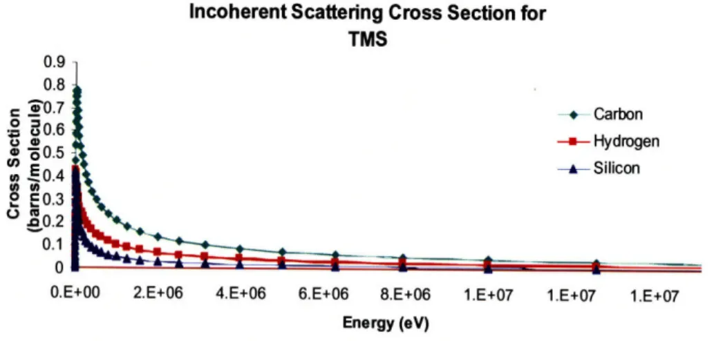
Gamma contamination is continuously an issue when detecting fast neutrons. A current approach to dealing with this problem is neutron-gamma discrimination. The discrimination process is done by various methods including pulse shape analysis, 10% -90% risetime measurements, time of flight, and figure of merit. The dielectric liquids under investigation provide an alternate solution for gamma contamination. In an ionization chamber, gamma rays are detected when Compton (incoherent) scattering occurs. Compton scattering is when gamma rays interact with the electrons of an atom in the target material and set a detectable electron free. Inherently, dielectric liquids are essentially gamma blind because the cross section for incoherent scattering in these liquids is extremely low. Figures 2.1, 2.2, and 2.3 illustrate the cross sections of incoherent scattering for hydrogen, carbon, and silicon for various photon energies. The data is normalized in order account for the ratios of each element within the molecule.
Incoherent Scattering Cross Section for TMS u.9 0.8 .c 0.7 60.6 . 50.5 , 0.4 0 E.3 S0.2 0.1 0
O.E+00 2.E+06 4.E+06 6.E+06 8.E+06 1.E+07 1.E+07 1.E+07 Energy (eV)
Figure 2.1 Incoherent scattering cross sections for hydrogen, carbon, and silicon target media at various photon energies for TMS.
Incoherent Scattering Cross Section for TMP
Sip
I.2-1 0.8 0.6 0.4 0.2 00.E+00 5. E+06 1. E+07
Energy (eV)
2.E+07
Figure 2.2 Incoherent scattering cross sections for hydrogen, carbon, and silicon target media at various photon energies for TMP.
Incoherent Scattering Cross Section for Isooctane 1 2
MM
RBi
1 0.8 0.6 0.4 0.2 0 0.E+00 - Carbon --- Hydrogen 5.E+06 1.E+07 Energy (eV) 2.E+07Figure 2.3 Incoherent scattering cross sections for hydrogen, carbon, and silicon target media at various photon energies for Isooctane.
Based on Figures 2.1, 2.2, and 2.3, incoherent scattering only appears to be an issue when low energy gammas are present. Shielding against those gammas with lead blocks should be an adequate solution.
Decreased Recombination
As discussed in Chapter 1, recombination is when an electron and a hole interact and neutralize each other. This is a problem if the electron-ion pair recombines after a
fast neutron ionizes them. The process of recombination causes the efficiency of the detector to be low because fast neutrons that are present cannot be detected. In ionization chambers, a sufficiently high electric field can minimize recombination. Since dielectric liquids are placed in between the chamber electrodes, the chamber can withstand high applied voltages. Another benefit of dielectrics is that when electric charges travel through them, the interaction energies and forces between the charges are reduced. This attribute discourages recombination.
High Density
High density is an advantageous quality in a fast neutron detector. Higher densities allow for thinner detectors, higher energy resolution, and higher efficiency. Gas detectors have low efficiency as a result of atoms being spread apart. The densities of substances are typically a factor of 102 to 103 larger in their liquid phase than in their gaseous phase. Consequently, the fast neutron detection efficiency would presumably be higher when liquid detection media, rather than gas, is used.
Fast Response
When electrons and ions in an ionization chamber are in the presence of an electric field, they migrate toward the oppositely charged electrode. As a result of the mass difference between the electrons and ions, the electron mobility is much faster than that of the ion. Most of the detection methods discussed in Chapter 1 are concerned with the detection of the ion or recoil proton. In ionization chambers, one has the choice of detecting the electrons, ions, or both. For the fastest response, it would make sense to only detect the electrons. This is done by implementing a shorter collection time than that necessary to detect ions.
Hydrogenous Composition
Hydrogen is the ideal elastic scattering nucleus when attempting to detect fast neutrons because fast neutrons transfer between 0 and 100 percent of their total kinetic energy to the hydrogen nucleus during a collision. The maximum transfer of kinetic energy is desired because it reduces the possibility of multiple neutron scattering. For
![Figure 1.1 Cross Section Energy Dependence for Popular Neutron-Induced Reactions [1].](https://thumb-eu.123doks.com/thumbv2/123doknet/14745857.578145/14.918.251.667.820.1067/figure-section-energy-dependence-popular-neutron-induced-reactions.webp)
![Figure 1.2 Calculated Response for a 100keV electron and 500keV neutron [5].](https://thumb-eu.123doks.com/thumbv2/123doknet/14745857.578145/25.918.275.655.129.379/figure-calculated-response-kev-electron-kev-neutron.webp)
![Figure 1.4 Risetime vs. pulse height plot at low-gain setting showing n/y PSD from a BC501A scintillator [17].](https://thumb-eu.123doks.com/thumbv2/123doknet/14745857.578145/26.918.298.606.462.703/figure-risetime-pulse-height-plot-setting-showing-scintillator.webp)