A Device for Harvesting Energy From Rotational Vibrations
The MIT Faculty has made this article openly available.
Please share
how this access benefits you. Your story matters.
Citation
Trimble, A Zachary et al. “A Device for Harvesting Energy From
Rotational Vibrations.” Journal of Mechanical Design 132, 9 (2010):
091001 © 2010 by ASME
As Published
http://dx.doi.org/10.1115/1.4002240
Publisher
ASME International
Version
Final published version
Citable link
http://hdl.handle.net/1721.1/119837
Terms of Use
Article is made available in accordance with the publisher's
policy and may be subject to US copyright law. Please refer to the
publisher's site for terms of use.
A Zachary Trimble
Precision Engineering Research Group (PERG), Department of Mechanical Engineering, Massachusetts Institute of Technology, Cambridge, MA 02139 e-mail: [email protected]
Jeffrey H. Lang
Professor of Electrical Engineering Laboratory for Electromagnetic and Electronic Systems (LEES), Department of Electrical Engineering and Computer Science, Massachusetts Institute of Technology, Cambridge, MA 02139 e-mail: [email protected]
Jahir Pabon
Scientific Advisor Schlumberger Doll Research Center, Cambridge, MA 02139 e-mail: [email protected]
Alexander Slocum
Professor of Mechanical Engineering Precision Engineering Research Group (PERG), Department of Mechanical Engineering, Massachusetts Institute of Technology, Cambridge, MA 02139 e-mail: [email protected]
A Device for Harvesting Energy
From Rotational Vibrations
A new device designed to harvest rotational vibration energy is presented. The device is modeled as a spring-mass-damper system connected to a vibration source where a tor-sion rod is used as a spring element and a shearing electromagnetic induction circuit as the energy harvesting element. The device is inherently a resonant type harvester. A prototype device is tested using a purely sinusoidal vibration input and more realistic inputs consisting of wider bandwidths, multiple resonance peaks, and low amplitude noise. The performance of the prototype to realistic inputs verifies the ongoing challenge to vibration energy harvesting, namely, significant loss of performance when using broad-band inputs with resonant based devices. 关DOI: 10.1115/1.4002240兴
1 Introduction
A significant amount of vibration in many rotating mechanical systems seems to be a viable potential source of energy for sen-sors and other instruments. In general, harvesting or scavenging kinetic energy associated with mechanical vibrations involves some form of electrical transducer to transform mechanical energy to electrical energy. Common forms of transduction include active materials, such as piezoelectric; and various forms of electromag-netic transduction, such as induction关1兴.
According to Ref. 关2兴, regardless of the transduction method, the majority of devices described in the literature rely on an iner-tial proof mass connected to the vibrating environment by combi-nations of springs and dampers. The majority of these devices are of microscale and are designed to accept linear inputs. However, as proposed by Ref.关3兴, since harvesting architectures based on a rotating proof mass have less restrictive displacement constraints, rotating architectures provide potential advantages over those based on linear systems. Additionally, as shown by Ref.关4兴 when using electromagnetic transduction as the method for energy har-vesting, a shearing magnetic circuit is more magnetically efficient than an axial or plunging circuit. A rotating proof mass naturally provides a shearing air gap taking advantage of the higher effi-ciency shearing magnetic circuit.
Several wrist watches have been successfully powered 共or wound兲 by rotating proof masses 关5兴, but in those instances, the frequency of vibration is very low共0.5–2 Hz兲, and the amplitude of vibration is several orders of magnitude larger than the size of the device. Thus, the majority of the work is done by the relative
change in the direction of the gravitational field associated with such large amplitude changes and not the relative motion pro-duced by inertial forces on the proof mass. To the authors’ knowl-edge, what is not available is a macroscale device capable of harvesting the higher frequency共5–100 Hz兲 but much lower am-plitude vibrations of rotating machinery in varying attitudes. As explained by Ref. 关6兴, most proposed methods of transduction have similar maximum potential power densities, and thus the choice is often application specific. Combining these results with the estimates of Ref.关4兴, electromagnetic induction is chosen as the best method of transduction for this device based on expected mechanical vibrations and form factor restraints. Thus, presented here are the design and performance of a rotational, macroscale,
energy harvester. The harvester uses a rotating
spring-mass-damper that can be directly connected to a rotational system sub-jected to torsional vibration and, through electromagnetic induc-tion, harvest the potential energy of those vibrations.
Often, initial estimates of the amount of energy that can be harvested from a vibration are based on an analytic solution of the system model to a single frequency harmonic input. However, Ref.关7兴 has shown that for actual accelerations, small additions of bandwidth or background noise greatly reduces the actual harvest-able power. Thus, because of the broad frequency spectrum and the possibly random phase of the expected vibration, our design approach is to develop an analytical model of rotational electro-magnetic energy harvesters that can receive the sample inputs and can predict the energy output from the machine. The theoretical development and explanation of the analytical model and design theory are presented first. The details of a prototype rotational harvester designed based on the theory are then presented, and test details are given for each element of the analytical model tested against the prototype design for model verification. Finally, both harmonic and example signals are simulated and tested against the model for verification.
Contributed by the Design Automation Committee of ASME for publication in the JOURNAL OFMECHANICALDESIGN. Manuscript received March 16, 2010; final manu-script received July 27, 2010; published online August 30, 2010. Assoc. Editor: Karthik Ramani.
2 Modeling
Conceptual operation of the device is relatively straightforward. Figure 1 is a lumped parameter model describing the operation. The system acts like a standard spring-mass-damper with base excitation. The device is built inside a casing that is attached to a vibrating source and thus acts as the vibrating reference frame. A spring element is provided by a torsion rod, an inertial “mass” element by a rotor core, and a damping element by a combination of unavoidable losses in the support bearings and the energy re-moved from the system represented in the model as an electro-magnetic torque. The second order governing differential equation describing the relative motion of the proof mass in terms of the system parameters and the vibration input can be written as
¨ +bi J˙ + 1 JTe+ K J = − ␣¨ 共1兲
This system is well studied in textbooks on vibration, and ideally the frequency of vibration input is matched with the resonant fre-quency, thus amplifying the magnitude of the relative motion and providing exponential gains in power.
Since the energy is harvested in an electromagnetic transducer, the model consists of two main components: a mechanical model and an electromagnetic model. As the magnets move relative to a coil attached to the base, they create a varying magnetic flux field relative to the base that generates an emf voltage in the coil. If a load is attached to the emf voltage potential, energy is removed from the system through the load; as a result, the current flowing through the coil to power the load generates a reaction torque that acts to dampen the vibration. The electromagnetic model calcu-lates the varying flux based on the elements in the magnetic cir-cuit共magnets, air gap, and back iron兲. Based on the flux calcula-tion, the expected voltage in a coil attached to the base is calculated. Assuming a resistive electrical load, the reaction torque is returned to the mechanical model as an additional damp-ing element. Key model components affectdamp-ing the power output are the mechanical quality factor共Q兲, natural frequency 共n兲, ro-tational inertia共J兲, and electrical damping coefficient 共be兲.
2.1 Magnetic Model. Electromagnetically, the device is
simi-lar to a standard rotary generator共Fig. 2兲. An outer casing acts as focusing back iron for a surface wound coil attached to the inside of the casing共or stator兲. Continuing concentrically inward, an air gap separates the coil from a set of magnets attached to a rotor that acts as focusing back iron for the magnets. Rare earth perma-nent magnets on the rotor provide a magnetic field in the air gap
between the magnets and steel casing. As the rotor moves relative to the case, the magnetic field thorough the coils changes and generates an emf voltage. According to Faraday’s law of induc-tion, the emf voltage can be written as
emf = =d dt= d d d dt = d d˙ 共2兲
Under some simplifying assumptions, the quasi-static versions of Maxwell’s equations can be used to solve for analytically. First, ignoring fringing fields at each end of the rotor, the 2D solutions for Maxwell’s equations can be used. Second, compar-ing the magnetic permeabilities and relative dimensions, the re-luctance of the focusing iron is sufficiently less than the rere-luctance in the air gap so that the iron can be assumed to be infinitely permeable and a perfect conductor, which simplifies the boundary conditions. Under these assumptions, the solution for the magnetic flux density is shown by Ref.关8兴 to be
Bជa=
兺
k=1 ⬁ − 2BR 共2k − 1兲ra0再
rarsin共p共2k − 1兲兲eˆr racos共p共2k − 1兲兲eˆ冎
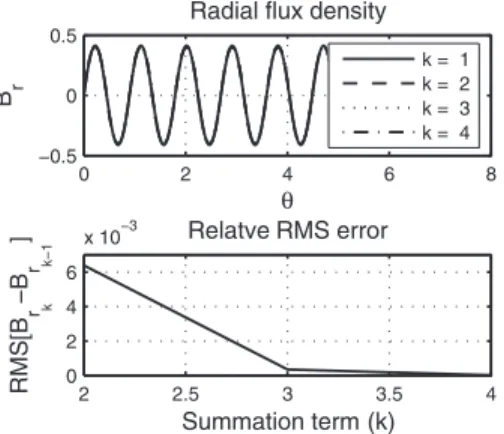
共3兲 Although Eq.共3兲 is an infinite summation as k→⬁, the magni-tude of the higher order harmonics tends to zero. As can be seen in Fig. 3, for the dimensions of the proposed prototype, the relative error between truncated estimates of the flux density amplitude evaluated at the casing surface quickly tends to zero. In fact, the relative error between an estimate using only the first term, k = 1, and an estimate using the first and second terms, k = 1 , 2, is lessVibration
Source
J
K
b
iT
eα
φ
Input Displacement Torsion Spring Relative Displacement Electrical Transducer M ec h an ica lL osses Rotor InertiaFig. 1 Lumped parameter model of the harvester
N S N N N N N N N N N N N N N S S S S S S S S S S S S S x y
φ
θ Back Iron (Stator) Back Iron (Rotor) Permanent Magnets r e M M= 0ˆ v r e M M=− 0ˆ v Air Gap Surface Current z e I i=−0ˆ v z e I i= 0ˆ v p π 2 ric rm rocFig. 2 Cross-sectional view of the magnetic circuit„to scale…
0 2 4 6 8
−0.5 0 0.5
Radial flux density
θ B r k = 1 k = 2 k = 3 k = 4 2 2.5 3 3.5 4 0 2 4 6 x 10⁻³ Relatve RMS error Summation term (k) RMS [B r k −B r k−1 ]
Fig. 3 Plot of the calculated radial flux density, Br, evaluated at
roc. Although Bris an infinite summation, as can be seen, the
influence of higher order terms is small and can be neglected.
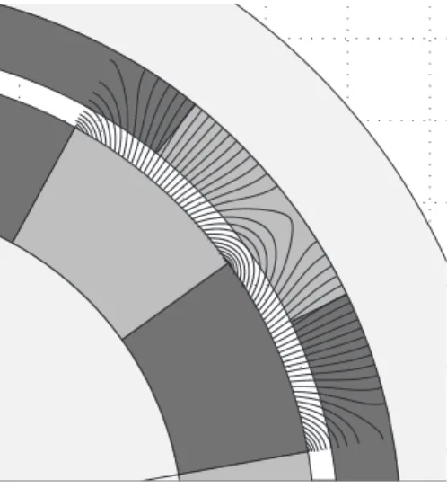
than 0.5%, and thus for dimensions of the proposed prototype the flux can be accurately estimated using only the first term, which greatly simplifies calculations. The magnetic flux density stream-lines calculated using these simplifications are shown in Fig. 4. Assuming that all the current in the coils is concentrated on the surface of the casing, only the radial component of flux density in the air gap region evaluated at roc is essential 共Fig. 3兲. Thus, integrating the first term in the summation of the flux density at the casing surface over the area of the coils and multiplying by the number of turns in the coils results in an equation for the flux passing through the coils,:
= 0sin共p共2k − 1兲兲 共4兲 where 0= 8NhBRrm
冋
冉
rm ric冊
p −冉
ric rm冊
p册
2冋
冉
ric roc冊
p −冉
roc ric冊
p册
共5兲Substituting this result into Eq.共2兲 results in an equation for the emf,
= 0p共2k − 1兲cos共p共2k − 1兲兲 共6兲
The calculated emf can then be used to find an equivalent damp-ing coefficient. Usdamp-ing an equivalent circuit model 共Fig. 5兲 and assuming a resistive load, the current in the windings is i = emf/共Rcoil+ Rload兲. The electromagnetic torque is then given by
T = i⫻ B 共7兲
Combining the previous results and integrating around the com-plete circle, the torque in the axial direction can be reduced to
Tez=
02p2Rload
2共Rload+ Rcoil兲2cos共p兲共˙兲 共8兲 from which the equivalent damping coefficient is
be=
0 2p2 Rload+ Rcoilcos
2共p兲 共9兲
Although beis technically a function of the displacement, for the small relative displacements expected cos共p兲⬇1 and the damp-ing coefficient can be approximated as
be⬇
02p2 Rload+ Rcoil
共10兲 This damping coefficient can be tuned by power electronics de-signed to be capable of varying the load resistance. However, useful power is only harvested in the load resistance and is gov-erned by the voltage divider equation,
Pl=共vl兲共i兲 =
冉
Rload Rload+ Rcoil冊冉
Rload+ Rcoil冊
= Rload2 共Rload+ Rcoil兲2 共11兲 The harvested power is at a maximum when Rload= Rcoil. Thus,although the damping coefficient can be fine tuned by varying
Rload, once the optimal damping coefficient is determined from the mechanics, the coils should be designed such that
Rcoil⬇0 2p2
2be
共12兲
2.2 Mechanical Model. With the electromagnetic torque
re-duced to an equivalent damping coefficient, be, Eq.共1兲 describing
the relative motion of the proof mass can be reduced to ¨ +bi+ be
J ˙ + K
J = − ␣¨ 共13兲
In this reduced form, the governing equation is the well studied base excitation equation. Remembering the power harvested is proportional to the relative velocity between the coils and the magnets, we see that to maximize the power harvested we must maximize the relative velocity. Using the solutions of Ref.关9兴, the relative velocity driven by a random input will be maximized by maximizing the product of the magnitude of transfer function and the power spectral density function of the input,
E关˙max2 兴 =
冕
−⬁ ⬁
兩H␣¨→˙共兲兩2S␣¨共兲d 共14兲
For the second order model proposed and expected representative spectral densities, this maximum results when the resonant fre-quency of the system matches the frefre-quency at the maximum amplitude of the power spectral density共PSD兲. Thus, the natural frequency
冑
K/m should coincide with the maximum amplitude ofthe Fourier decomposition of the input signal关10兴.
For a harmonic input, if n=, then the power becomes
di-rectly proportional to the proof mass. For a random signal, an analytical solution is not possible, but assuming superposition, this solution would still apply for the single term at the resonant frequency and would be approximately true for all terms near the resonant frequency. Thus, the power is approximately linearly proportional to the proof mass. Combining these two criteria, the proof mass should be maximized for the given volume, and then the spring constant K should be chosen to providen=Amax.
The damping coefficient is then used to tune the match between the transfer function and the PSD. Since only the electrical damp-ing be is harvestable and the remaining damping is attributed to
losses, the internal losses should be reduced as much as possible. The electrical damping can then be chosen to maximize the power. For some inputs, such as harmonic, the solution can be determined analytically and results in be= bi; however, in most cases, be should be chosen numerically by the simulation of the expected input.
Fig. 4 B field streamlines„single magnet pair…
ε
Ri RL i LV
L L iV P =3 Prototype Design and Testing
The theory was used to create a design code that enabled an experimental prototype to be designed, built, and tested. The de-vice was required to fit into a defined cylindrical form factor of 1.25 in. 共31.8 mm兲 diameter and 5 in. 共127 mm兲 length. The device is comprised of a 1.25 in.共31.8 mm兲 diameter, 0.1 in. 共2.5 mm兲 thick steel cylinder casing, which provides the structural ground/attachment for the device as well as acts as the stator back iron. An electrical coil wound from a 32AWG magnet wire is attached to the inner surface of the steel. A 0.9 in.共22.9 mm兲 outer diameter rotor assembly comprised of a steel core with neodymium-boron permanent magnets attached around the out-side is located in the center of the device by ball bearings at each end. At one end of the rotor assembly, a Nitinol piano wire is rigidly affixed to the steel core and passes axially through the hollow center of the core where it is rigidly affixed to the casing and acts as the torsion spring共Fig. 6兲.
Although in operation the electrical and mechanical models are coupled, the prototype is designed so the electromagnetic model can be tested separately from the mechanical model. Thus, each of the model parameters can be verified independently. Starting with the electromagnetic model, the model is verified by comparing the expected emf to the measured output from the device under a constant rotational velocity input共the torsion spring is removed so
the rotor can spin freely with respect to the stator兲. As can be seen in Fig. 7, when operating the harvester like a generator, the pre-dicted voltage output is nearly identical to the measured voltage, suggesting that the proposed electromagnetic model is correct.
Turning now to the mechanical model, the model is verified piecewise. The moment of inertia of the rotor is determined from the solid model and is verified by comparing the predicted mass and dimensions of the solid model to the measured mass and dimensions of the device. The natural frequency of the system is verified by comparing the maximum amplitude of the open circuit voltage to a swept single frequency sinusoidal input. The me-chanical Q of the system is experimentally determined by com-paring the calculated open circuit voltage to the measured voltage for a single frequency sinusoidal input. The open circuit voltage is determined by solving the mechanical model 共Eq. 共13兲兲 for the relative motion 共where in open circuit be= 0兲 and then using the
calculated in the electrical model 共Eq. 共6兲兲 to determine the voltage. Figure 8 is a plot of the voltage as a function of time for a single frequency harmonic input, and Fig. 9 is a plot of the voltage amplitude as a function of frequency for a single fre-quency harmonic input slowly swept through the frefre-quency spec-trum. The agreement of the experimental and calculated values in Figs. 8 and 9 suggests that the assumptions made to create the model are appropriate and represent the form of the equation and additionally suggests that the physical parameters have been prop-erly calculated.
Combining all the components for a single frequency input of the same typical frequency and amplitude as the Fourier decom-position of an example realistic acceleration input共Fig. 10兲, the
Fig. 7 Verification of emf model „V=0sin„pt +… and 0
= 0.0073We… 0 0.1 0.2 0.3 0.4 −4 −2 0 2 4
Time [s]
Voltage
[V]
Calc. Meas.Fig. 8 Plot of the emf voltage versus time in open circuit
op-eration for a single frequency input. As can be seen, the experi-mentally measured voltage is nearly identical to the predicted voltage. A A B C D E F F H G G
Fig. 6 Solid model„exploded and cross section… of the
proto-type design: A, end caps/bearing supports; B, casing; C, rotor; D, magnets; E, torsion rod; F, torsion rod clamps; G, bearings; H, coil 5 10 15 20 25 30 0 1 2 3 4 Freq [Hz] Voltage [V] Calc. Meas.
Fig. 9 Plot of the amplitude of emf voltage as a function of
frequency for a single frequency input. Each of the “x’s” repre-sent an independent experiment at the input frequency shown. As can be seen, the experimentally measured voltage coin-cides with the predicted voltage.
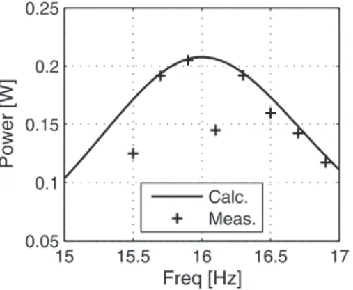
model predicts that 220 mW can be harvested, and experimental tests verify a harvested power of about 205 mW 共Fig. 11兲. As mentioned previously, a primary challenge to resonant based en-ergy harvesters in application is the wide, noisy nature of realistic vibrations. As an example, Ref.关11兴 presented a linear vibration spectrum that was excited by a rotating system. The spectrum presented shows multiple frequency peaks in close proximity, which will cause interference with resonance. Figure 10 is a plot of an example vibration spectrum. Given this input, the theoretical model predicts 85 mW average power during the 5 s input, and experimental tests verify an average harvested power of 74 mW. Figure 12 is a plot of the voltage as a function of time with the acceleration input from Fig. 10 and loaded by a 10 ⍀ resistor. As can be seen, the model accurately predicts the voltage across the load共and thus the power兲 from the wide-band signal. Notice that although the maximum acceleration amplitude of the vibration input is the same as the single frequency test, the harvested power is reduced by roughly a factor of 2. This illustrates one of the ongoing problems of resonant based harvesters. Possible solutions
to this problem in the literature include multifrequency resonators such as those presented in Ref.关12兴 or tunable harvesters such as those presented in Refs.关13,14兴; however, these approaches only work if the input consists of highly separated distinct frequency peaks. For noisy or closely spaced frequency spectra, a viable solution is still needed.
4 Conclusion
As outlined, the aim of this work was twofold. First, due to the random nature of most “real-world” vibrations, the design ap-proach was to create and verify a detailed model that can be used to accurately predict the power output of torsional vibration har-vesters when subjected to random inputs. For a single frequency harmonic input, Ref.关21兴 shows that the maximum power that can be harvested is
Pmax=J␣¨0
2Q
16n
共15兲 which for the prototype harvester with an assumed quality factor of 60 would predict a maximum power output of 245 mW. How-ever, when the prototype and the model are subjected to a wide-band real-world input, the power falls off by nearly an order of magnitude. However, the more detailed model accurately predicts the reduced power. Based on the accuracy of the models when compared with the prototype design, the design tools can be used with confidence for evaluating the potential power that can be harvested from real world signals. Additionally, with some changes to the electromagnetic model, the basic structure can be easily adapted to linear systems for similar evaluations.
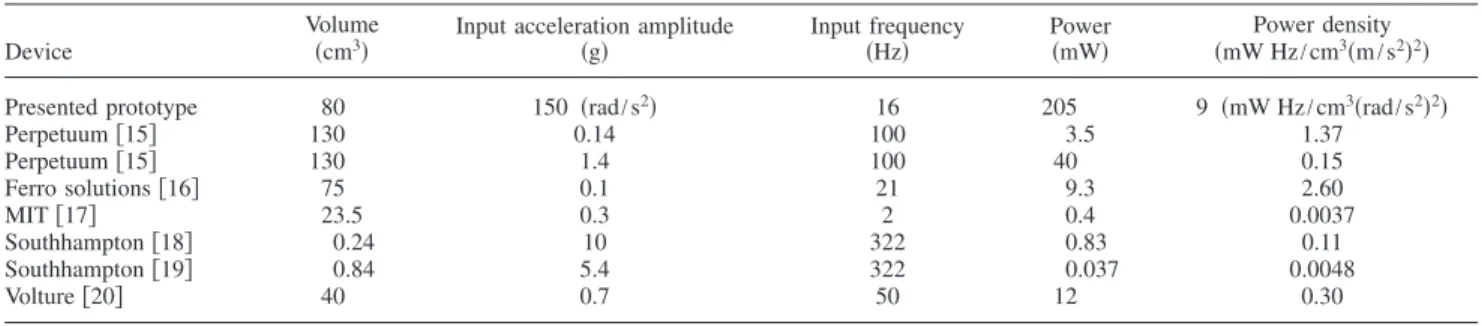
Second, a macrosized harvester placed in the center of a rotat-ing system designed to directly harvest torsional vibrations is a viable method to harvest energy from rotating systems. Although a direct comparison of a device attached to the exterior of the rotating system and harvesting the near linear acceleration inputs of a rotationally oscillating system at some distance from the cen-terline with a device similar to the one presented would be ideal, this comparison is not currently available. As a substitute, Eq.共15兲 shows that normalizing the power by the inertia, acceleration am-plitude squared, and natural frequency provides a reasonable power density for comparison. Note that for harmonic inputs, this is the same as normalizing by the mass, velocity, and acceleration, which come directly from the definition of power. However, since volume is more commonly reported and mass and volume can be assumed to be proportional, an approximate normalization using the device volume is used. Table 1 shows the comparison of power densities. As can be seen, the torsional device has compa-rable power densities, suggesting that this approach is viable.
Nomenclature
Bជ ⫽ magnetic flux density
Bជa ⫽ magnetic flux density in air gap region
BR ⫽ remanence of permanent magnets
兩H␣¨→˙兩 ⫽ magnitude of the complex frequency response
function relating input acceleration and output velocity
J ⫽ mass moment of inertia of proof mass K ⫽ torsion spring constant
N ⫽ number of turns in the coil Q ⫽ mechanical quality factor Rcoil ⫽ electrical resistance in coil Rload ⫽ electrical resistance of load
S␣¨ ⫽ power spectral density of the input acceleration
Tជ ⫽ torque
Te ⫽ electrical transducer torque
be ⫽ equivalent electrical damping coefficient
bi ⫽ internal damping coefficient
h ⫽ axial dimension of the coils and magnets 0 0.1 0.2 0.3 0.4 0.5 −100 0 100 Time [s] R o ta ti o n a l A c c el . ra d s s 14 16 18 20 22 0 5 10 Frequency [Hz]
Fig. 10 Example real-world signal the device is expected to
produce energy from. Shown are the time and frequency de-compositions of the desired signal and the actual signal. The input vibration was provided to the device without feedback control; however, as can be seen, the actual input signal is still
representative of a wide-band vibration as commonly
encountered. 15 15.5 16 16.5 17 0.05 0.1 0.15 0.2 0.25 Freq [Hz] P ower [W] Calc. Meas.
Fig. 11 Plot of the power versus frequency for a single
fre-quency input at approximately the same amplitude as the ex-ample realistic signal shown in Fig. 10
3 3.1 3.2 3.3 3.4 3.5 -4 -2 0 2 4 Time [s] Volt age [V ] Numerically Calculated Measured
Fig. 12 Plot of the voltage across a load resistor as a function
iជ ⫽ coil current
p ⫽ number of magnetic pole pairs ra
0 ⫽ nondimensional magnetic scaling factor
共common兲
ra
r ⫽ nondimensional magnetic scaling factor 共radial
direction兲
ra
⫽ nondimensional magnetic scaling factor 共theta
direction兲
ric ⫽ radial dimension to the inner surface of
magnets
rm ⫽ radial dimension to the outer surface of
magnets
roc ⫽ radial dimension to the inner surface of casing
␣¨ ⫽ reference frame acceleration
␣¨0 ⫽ amplitude of the acceleration input if␣¨ is
harmonic ⫽ emf voltage ⫽ magnetic flux
0 ⫽ amplitude of magnetic flux
⫽ relative rotation ˙ ⫽ relative velocity ¨ ⫽ relative acceleration
References
关1兴 Arnold, D., 2007, “Review of Microscale Magnetic Power Generation,” IEEE Trans. Magn., 43共11兲, pp. 3940–3951.
关2兴 Mitcheson, P., Green, T., Yeatman, E., and Holmes, A., 2004, “Architectures for Vibration-Driven Micropower Generators,” J. Microelectromech. Syst.,
13共3兲, pp. 429–440.
关3兴 Yeatman, E., 2008, “Energy Harvesting From Motion Using Rotating and Gy-roscopic Proof Masses,” Proc. Inst. Mech. Eng., Part C: J. Mech. Eng. Sci.,
222共1兲, pp. 27–36.
关4兴 Jonnalagadda, A., 2007, “Magnetic Induction Systems to Harvest Energy From Mechanical Vibrations,” MS thesis, Massachusetts Institute of Technol-ogy, Cambridge, MA.
关5兴 Chapuis, A., and Jaquet, E., 1956, The History of the Self-Winding Watch, Roto-Sadag SA, Geneva.
关6兴 Roundy, S., 2005, “On the Effectiveness of Vibration-Based Energy Harvest-ing,” J. Intell. Mater. Syst. Struct., 16共10兲, pp. 809–823.
关7兴 Halvorsen, E., 2008, “Energy Harvesters Driven by Broadband Random Vi-brations,” J. Microelectromech. Syst., 17共5兲, pp. 1061–1071.
关8兴 Haus, H., and Melcher, J., 1989, Electromagnetic Fields and Energy, Prentice-Hall, Englewood Cliffs, NJ.
关9兴 Inman, D. J., 2001, Engineering Vibrations, 2nd ed., Prentice-Hall, Englewood Cliffs, NJ.
关10兴 Newland, D., 1984, An Introduction to Random Vibrations and Spectral
Analy-sis, Longman, New York.
关11兴 Johnson, T., Charnegie, D., Clark, W., Buric, M., and Kusic, G., 2006, “Energy Harvesting From Mechanical Vibrations Using Piezoelectric Cantilever Beams,” Proc. SPIE, 6169, p. 61690D.
关12兴 Yang, B., Lee, C., Xiang, W., Xie, J., He, J., Kotlanka, R., Low, S., and Feng, H., 2009, “Electromagnetic Energy Harvesting From Vibrations of Multiple Frequencies,” J. Micromech. Microeng., 19, p. 035001.
关13兴 Challa, V. R., Prasad, M. G., and Fisher, F. T., 2009, “Towards a Self-Tunable, Wide Frequency Bandwidth Vibration Energy Harvesting Device,” ASME 2009 International Mechanical Engineering Congress and Exposition, pp. 57– 65.
关14兴 Challa, V. R., Prasad, M. G., Shi, Y., and Fisher, F., 2007, “A Wide Frequency Range Tunable Vibration Energy Harvesting Device Using Magnetically In-duced Stiffness,” ASME 2007 International Mechanical Engineering Congress and Exposition, pp. 387–395.
关15兴 Perpetuum, energy harvesting microgenerator product data sheet. 关16兴 Solutions, F., 2009, http://www.ferrosi.com/energy-harvesters.html 关17兴 Amirtharajah, R., and Chandrakasan, A., 1998, “Self-Powered Signal
Process-ing UsProcess-ing Vibration-Based Power Generation,” IEEE J. Solid-State Circuits,
33共5兲, pp. 687–695.
关18兴 El-hami, M., Glynne-Jones, P., White, N. M., Hill, M., Beeby, S., James, E., Brown, A. D., and Ross, J. N., 2001, “Design and Fabrication of a New Vibration-Based Electromechanical Power Generator,” Sens. Actuators, A, 92, pp. 335–342.
关19兴 Glynne-Jones, P., Tudor, M. J., Beeby, S. P., and White, N. M., 2004, “An Electromagnetic, Vibration-Powered Generator for Intelligent Sensor Sys-tems,” Sens. Actuators, A, 110共1–3兲, pp. 344–349.
关20兴 MES Technologies, 2010, http://www.mide.com/pdfs/ volture_specs_piezo_properties.pdf
关21兴 Trimble, A. Z., 2007, “Downhole Vibration Sensing by Vibration Energy Har-vesting,” MS thesis, Massachusetts Institute of Technology, Cambridge, MA.
Table 1 Comparison of prototype device to other devices in the literature„note: the presented device is to the authors’
knowl-edge the only rotational harvester and is thus compared against a selection of linear harvesters…
Device
Volume 共cm3兲
Input acceleration amplitude
共g兲 Input frequency共Hz兲 Power共mW兲 共mW Hz/cmPower density3共m/s2兲2兲
Presented prototype 80 150 共rad/s2兲 16 205 9 共mW Hz/cm3共rad/s2兲2兲
Perpetuum关15兴 130 0.14 100 3.5 1.37 Perpetuum关15兴 130 1.4 100 40 0.15 Ferro solutions关16兴 75 0.1 21 9.3 2.60 MIT关17兴 23.5 0.3 2 0.4 0.0037 Southhampton关18兴 0.24 10 322 0.83 0.11 Southhampton关19兴 0.84 5.4 322 0.037 0.0048 Volture关20兴 40 0.7 50 12 0.30