Convective Heat Transfer in Rotating, Circular Channels by
Brenna Elizabeth Hogan
Submitted to the
Department of Mechanical Engineering
in Partial Fulfillment of the Requirements for the Degree of Bachelor of Science in Engineering as Recommended by the
Department of Mechanical Engineering at the
Massachusetts Institute of Technology
June 2012
ARCHIVES
MASSACHUSETTS INST OF TECHNOLOGYJUN 28 2012
LIBRARIES
@ 2012 Massachusetts Institute of Technology. All rights reserved.
Signature of Author:
Department of Mechanical Engineering May 25, 2012
Certified by:
Accepted by:
Cullen R. Buie Mitsui Career Development Assistant Professor Thesis Supervisor
John H. Lienhard V Samuel C. Collins Professor of Mechanical Engineering Undergraduate Officer
Convective Heat Transfer in Rotating, Circular Tubes
by
Brenna Elizabeth Hogan
Submitted to the Department of Mechanical Engineering on May 25, 2012 in Partial Fulfillment of the
Requirements for the Degree of
Bachelor of Science in Engineering as Recommended by the Department of Mechanical Engineering
ABSTRACT
Nusselt number values for flow in a rotating reference frame are obtained through computational fluid dynamic (CFD) analysis for Rossby numbers Ro ~1-4 and
Reynolds numbers Re ~1,000-2,000. The heat-transfer model is first validated according to Nusselt number correlations for laminar, developing flow in circular tubes and by friction factor
correlations for fully developed flow in circular tubes rotating at constant angular velocity about an orthogonal axis. The data show heat-transfer enhancement for increasing rotational speeds, as predicted through secondary flows caused by Coriolis forces. Moreover, the heat-transfer
enhancement is found to be greater than the resulting increase in friction losses due to secondary flows.
Thesis Supervisor: Cullen R. Buie
Acknowledgements
I would like to thank my thesis supervisor, Professor Cullen R. Buie, for his guidance and patience.
I am indebted to Dr. Lino Gonzalez for his help, support, and patience throughout the process. I am grateful for all the time he devoted to helping me, and I have learned so much from him. I would like to thank my friends and family who supported me throughout the many trials of MIT.
Table of Contents Acknowledgements 3 Table of Contents 7 List of Figures 8 List of Tables 9 List of Variables 11 1. Introduction 13
2. Formulation of the Problem 13
3. Dimensional Analysis using Buckingham Pi Theorem 16
3a. Non-Rotating Circular Pipe 17
3b. Rotating Circular Pipe 17
4. Model Validation 17
4a. Forced Convection for Laminar Flow inside a Circular Tube under Constant
Wall Condition 18
5. Cylindrical Tube Rotating Around Orthogonal Axis 21
5a. Friction Factor-Rotating Reference Frame 21
5b. Nusselt Number-Rotating Reference Frame 23
6. Results 24
7. Conclusion 32
List of Figures
Figure 1. Circular cross-section tube rotating about perpendicular axis 13 Figure 2. Average Nusselt number results obtained from thermal entry length correlation for
laminar flow in a circular tube 20
Figure 3. Average Nusselt number results obtained for laminar, combined entry length in a
circular tube 21
Figure 4. Friction factor results obtained for rotating laminar, fully-developed flow in cylindrical
tube 23
Figure 5a. Cross-section at outlet of cylindrical tube showing parabolic velocity profile in
stationary (i.e. no rotation) case 24
Figure 5b. Contours of z-velocity showing velocity distribution inside cylindrical tube in
non-rotating case 24
Figure 6a. Cross-section at outlet of cylindrical tube showing parabolic velocity profile shift for low rotational speed, 92= 60 rpm, for channel rotating counter-clockwise about the y-axis 25 Figure 6b. Contours of z-velocity showing velocity distribution inside cylindrical tube in low-rotation case for channel rotating counter-clockwise about the y-axis. 25 Figure 7a. Cross-section at outlet of cylindrical tube showing parabolic velocity profile shift for low rotational speed, 92= 300 rpm, for channel rotating counter-clockwise about the y-axis 26 Figure 7b. Contours of z-velocity showing velocity distribution inside cylindrical tube in
rotation case 92= 300 rpm for channel rotating counter-clockwise about the y-axis 26 Figure 8a. Cross-section at outlet of cylindrical tube showing parabolic velocity profile shift for high rotational speed, 92= 2000 rpm, for channel rotating counter-clockwise about the y-axis 27 Figure 8b. Contours of z-velocity showing velocity distribution inside cylindrical tube in
rotation case K2= 2000 rpm for channel rotating counter-clockwise about the y-axis 27 Figure 9. Average Nusselt number results obtained over length of tube for Ro- 4.1, 2.2, 1.5, 1.7
and Re- 1,200, 2,000 28
Figure 10. Average Nusselt number obtained for axial positions for Re- 1,200 and Ro-4.1, 2.2,
1.5, 1.7 29
Figure 11. Average Nusselt number obtained for axial positions for Re-2,000 and Ro-4.1, 2.2,
Figure 12. Average Nusselt number obtained for Ro-1.2 for Re-1,200 and Re-2,000 30 Figure 13. Ratio of heat transfer enhancement to friction losses 31 Figure 14. Ratio of heat transfer enhancement to friction factor as a function of Ro for
theoretical model developed using Ito's friction factor correlation and Mori and Fukata's Nusselt
List of Tables
List of Variables
v = mean axial velocityGo = constant angular velocity
D = diameter of pipe
yi= dynamic viscosity
p density
= kinematic viscosity
L axial length of channel
k = thermal conductivity c= specific heat
z = axial location
E= viscous dissipation
q = heat generation in the fluid (i.e. from a chemical reaction)
h coefficient of convective heat transfer V velocity vector in inertial frame
V= velocity vector in rotating reference frame angular velocity vector
F = vector of body forces in the stationary reference frame (i.e. gravity) r = radial position vector
P = static pressure
P*= dynamic pressure in rotating system T= wall surface temperature
Qconv = total heat transfer rate to the fluid through convection
h = average heat transfer coefficient
ATim= log-mean temperature difference
Tmo mean outlet temperature
Tmi mean inlet temperature
ATO TS - Tmo
AT, TS - Tmi
1. Introduction
The study of flow and heat transfer in the rotating reference frame has important
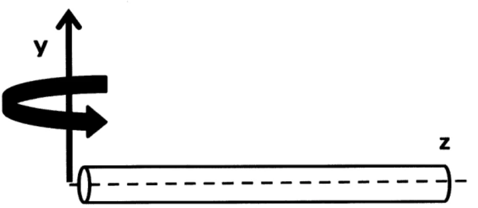
implications for real world applications. Rotation gives rise to secondary flows, perpendicular to the primary radial flow. These secondary flows are produced by Coriolis forces in the rotating reference frame. The case of a straight circular cross-section channel rotating around a
perpendicular axis, as shown in Figure 1, is examined in this work.
Y
z
Figure 1. Circular cross-section tube rotating about perpendicular axis
Rotation is relevant in the study of cooling passages because rotation influences cooling performance via secondary flows generated because of Coriolis forces and centripetal buoyancy [6]. Rotation improves heat transfer from the stationary case by increasing heat transfer on the trailing edge of the channel compared to the leading edge, resulting in an overall increase in the convective heat transfer coefficient. However, an increase in the flow resistance from the stationary case is also seen with rotation. A study of the influence of rotation of various geometries on heat transfer and flow resistance has practical importance in the development of cooling technologies, such as in rotating cooling passages used in cooling systems for the rotor blades of gas turbines.
The objective of this work is to study heat transfer in rotating tubes of circular cross-section and to obtain Nusselt number and friction factor correlations for various flow conditions. In this work, we consider developing laminar flow at constant wall temperature subject to perpendicular rotation, where the flow direction is perpendicular to the axis of rotation. In particular, the focus is on the limiting case where the flow is purely radial, as depicted in Figure
1.
2. Formulation of the Problem
We consider the motion of a fluid in a channel rotating with a constant angular velocity. The Navier Stokes, or momentum, equation in the inertial reference frame is given by:
where the left hand side describes acceleration of the fluid particle and the right hand side is a summation of body forces and divergence of stress including pressure and shear stress. In the rotating frame of reference, the total derivative term of the left-hand side becomes
=D - V* VV* + Q x ( x ) + 2 x V* (2)
De at
where C x (C x ir) is the centrifugal force and 2n x V7 is the Coriolis force. Substituting the rotational terms to the Navier-Stokes gives
+ - 2[n x V*] + F (3)
at p
By vector identity, the centrifugal acceleration term can be expressed as
-U x (n x r) = V( x
f
21)
(4)2
A new pressure-like variable P* can be defined as
P* =P - Inx |2 (5)
2
which represents the pressure modified by the centrifugal force [1]. This substitution is
commonly made in the rotating reference frame to separate dynamic from hydrostatic pressure. Since the flow is steady with respect to the rotating coordinate system and gravitational forces are assumed to be negligible, the time derivative term on the left hand side of Equation (3) disappears and the vector of body forces in the stationary reference frame, F, on the right hand
side disappears as well. Equation (3) thus becomes
V7 -T V*= + SV2
T - 2[n x T] (6)
P
Equation (6) can be non-dimensionalized by introducing the dimensionless variables
, P* P* 1
V* - -IQ 2 =- V'= DV
which gives
+
AV
v -[n
x V*] (7)p Dv v
The inverse Reynold and Rossby numbers appear from the dimensionless momentum equation. Substituting the known dimensionless parameters, we obtain
T
7p = V + 1 R0'2V [ ]
The non-dimensional Reynolds and Rossby numbers are explicitly given as
Re = D (9)
Ro = -(10)
2DQ0
The Reynolds number is a dimensionless number that is the ratio of inertial to viscous forces. Laminar flow occurs at low Reynold's numbers where viscous forces dominate the flow and the flow is characteristically smooth. At high Reynold's numbers, the flow is dominated by inertial forces which tend to produce eddies, vortices, and other flow instabilities, and the flow is said to be turbulent. The Rossby number is the ratio of inertial to Coriolis forces. A small Rossby number signifies flow strongly affected by Coriolis forces, and a large Rossby number indicates flow in which inertial and centrifugal forces dominate.
In addition to the momentum equation, the continuity equation given by
+ VpV* = 0 (11)
at
and the energy equation is
PC, +
VVT)
= V(kVT) + p(E + q) (12)where E represents viscous dissipation in the fluid and q represents heat generation in the fluid (i.e. from a chemical reaction), and k is the thermal conductivity of the fluid. Our flow is steady, includes no viscous dissipation or chemical reactions, and we assume constant properties. For our flow, the energy equation then becomes
/VT = aV2T (13)
Where a = k is the thermal diffusivity of the fluid. The choice of non-dimensionalizing PCP
parameters in this case will be D, a, and v.
DVVT = aV2T
(14) The dimensionless group on the left-hand side is defined as the Peclet number,
Pe = - = RePr (15)
where
Pr = (16)
The Prantl number is a dimensionless number which is the ratio of momentum diffusivity to thermal diffusivity. Our experiments involve air, which has a Prandtl number of 0.7. With a Prandtl number ~ 1, the momentum and thermal boundary layers will develop at the
approximately the same rate, so the hydrodynamic and thermal entrance lengths are approximately equal.
Based on the dimensionless analysis just performed, we expect the heat-transfer coefficient in a fully developed rotating system to be a function of the three dimensionless parameters: Re, Ro, Pr. In the case of developing flow, we therefore expect the Nusselt number Nu to be governed by the relationship
Nu = f (Re, Ro, Pr, (17)
This analysis supplemented in the following section by dimensional analysis using the Buckingham-Pi Theorem.
3. Dimensional Analysis using Buckingham-Pi Theorem
In an attempt to capture the dynamics of combined flow and heat-transfer experiments, relevant dimensionless parameters must be determined. An analysis of relevant dimensionless parameters for the non-rotating and rotating cases was conducted. Relevant parameters in the problem were determined and are summarized in Table 1 below.
TABLE 1. Relevant parameters for non-rotating and rotating flow through cylindrical pipe
In conducting an analysis of the relevant dimensionless parameters for each problem, we can apply the Buckingham Pi-Theorem. The Buckingham Pi-Theorem states that for n physical variables defining a problem andj independent fundamental physical quantities there are s relevant dimensionless parameters related by the equation,
Parameter Description Unit
v Mean axial velocity m/s
D Diameter of pipe r
19 Kinematic viscosity m2/s
p Density kg/m3
L Axial length r
[4 Rotation rate of channel 1/s
k Thermal conductivity W/(mK)
a Thermal diffusivity m2/S
AT Temperature difference K
h Coefficient of convective heat W/(m2K) transfer
s = n- (18)
3a. Non-Rotating Circular Pipe
For the non-rotating case, with an entry length (both thermal/hydrodynamic or only thermal/fully developed hydrodynamic), the independent physical variables characterizing the problem include v, D,p, a, V9, L, k, h, and AT. In the stationary case, the four relevant
dimensionless numbers are typically listed as:
vD D L hD
Re = , Pr = -, Le =-, Nu=
-R - a D k
The two new dimensionless parameters introduced are the entrance length and the
Nusselt number. As the flow enters the channel, there is an entrance length in which the thermal and hydrodynamic boundary layers develop. Nusselt number correlations will be derived for both the developing and fully-developed conditions for both the rotating and non-rotating cases. In addition, the Nusselt number appears. The Nusselt number is a dimensionless number which is a ratio of the convective to conductive heat transfer at a surface within the fluid. Larger Nusselt numbers correspond to higher convection heat transfer and are therefore more desirable in cooling applications.
3b. Rotating Circular Pipe
With channel rotation, the relevant dimensionless parameters include the entire set included in Table 1: v, D,p, a, 1, L, k, h, AT, and 20. An extra pi-group from the non-rotating
case appears, so that in the rotating case, there are five dimensionless groups.
vD D L hD v
Re =- - Pr =- Le = -. Nu =- Ro =
D a' D' k J'2DE20
The Rossby number is a ratio of inertial to Coriolis forces in a rotating flow. The Rossby numbers we will deal with are small, meaning Coriolis forces will dominate over inertial forces.
4. Model Validation
The first cases to be considered are for stationary circular tubes with constant wall temperature for both hydrodynamically fully developed/thermally-developing flow and co-developing flow. The conditions are realized in computational fluid dynamics software, ANSYS FLUENT, and results are obtained and compared against correlations found in literature.
The model then considers the effects of rotation on internal flow within circular tubes. Ito [4] provides an empirical friction factor correlation for fully-developed flow in straight pipes of circular cross section rotating about an axis perpendicular to the flow direction. Simulations
are run in ANSYS FLUENT and the results compared to Ito's empirical results. After the flow model is validated, the Nusselt numbers for developing and fully developed flow are obtained.
In order to properly execute the model and obtain accurate results, grid independence must be achieved so that the results of the simulations are not a function of the quality of mesh used. Different meshes were used until the results were independent of the size of mesh used. A mesh with inflation around the cylinder walls was used.
4a. Forced Convection for Laminar Flow inside a Circular Tube under Constant Wall Condition
In a circular tube characterized by laminar, fully developed flow with constant surface temperature, the Nusselt number is a constant, independent of Re, Pr, and axial location.
NUD = 3.66 for Ts = constant (19)
However, for the entry region both temperature and velocity depend on axial position z and radial position r. In this case, the Nusselt number is a function of Re, Pr, and axial location. Convection heat transfer with laminar flow in a circular tube (Re<2300) was examined for developing and fully developed flow with constant temperature walls.
For fully developed flow in a pipe where L
>>
Le with constant temperature walls,Nu=3.66. For laminar flow, the hydrodynamic entrance length can be estimated by [5] Le = 0.06Re
(20) D
Two different correlations for laminar flow in the entry region were examined- one for fully-developed hydrodynamic, developing thermal flow and the second for co-developing (both thermally and hydrodynamically) flow. The Nusselt numbers are infinite at z=0 and decay asymptotically to the fully developed value (NUD = 3.66 in the case of constant temperature
walls) as axial distance increases. Both entry length conditions were simulated in FLUENT. For entry length correlations, the Graetz number is created (allowed by the Buckingham Pi Theorem), which is a function of the three dimensionless parameters found above, Re, Pr, Le, and where we instead use the variable z to denote axial location within the tube.
GZD =
(D)
RePr (21)The first correlation looked at is the simpler case of the two. This correlation is for a thermal entry length and is based on the assumption that thermal conditions develop in the presence of a fully developed velocity profile. This situation can be realized physically by an unheated starting length which precedes the portion where heat transfer occurs, or by specifying a laminar velocity profile at the inlet. The Hausen [3] correlation for average Nusselt number
with constant surface temperature with hydrodynamically developed, thermally developing flow is given by:
NUD = 3.66 + 1+.O46GrD1
- hD
where NUD
T
To find the average convection coefficienth, Equation (23) is usedQconv
AsATIm
where ATim is defined as
A T,. 'T-a -"
m In (ATO/AT)
Whatever heat is transferred to the fluid through convection goes into heating up the fluid, so that
Qconv = rhc, (ATO - ATi) where
7t = pV-Dz
4
Substituting Equations (24), (25), and (26) above, we obtain
NUD = =4Lk
In
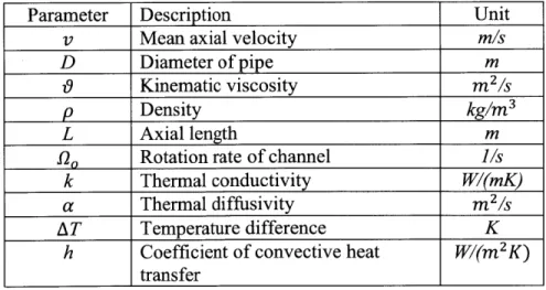
\AT{j)0/ (22) (23) (24) (25) (26) (27) CFD simulations were done to calculate the average Nusselt number for the thermal entry length, and Figure 2 shows the predicted Nusselt Number correlation and the results obtained from CFD.Thermal Entry Length Condition 6- 5-4 0 0.1 02 03 Gz^(-1)
Figure 2. Average Nusselt number results obtained from thermal entry length correlation for laminar flow in a circular tube
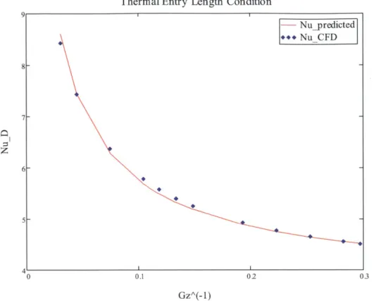
In the second case, a combined (thermal and hydrodynamic) entry length is considered in which the temperature and velocity profiles develop simultaneously. For the combined entry length, the suitable correlation given by Sieder and Tate [2] is given in Equation (28).
Nu = 1.86(Gz)3 (As) (28)
Sieder and Tate give the correlation for values of Prandtl number 0.48 < Pr < 16,700 and for 0.0044 < (t < 9.75. The Sieder-Tate correlation also takes into account the change in viscosity (pt and pu) Since we have assumed constant properties, the I term equals one in our case. The correlation has been recommended by Whitaker [7] for values of Gz3( )o" > 2, which is met for all axial locations studied for this case.
Codeveloping Condition 20 - Nu_predicted +++ NuCFD 15 S10-0 0.02 0.04 o06 008 0.1 GzA(- 1)
Figure 3. Average Nusselt number results obtained for laminar, combined entry length in a circular tube
As observed in Figures 2 and 3, the CFD model accurately predicts the Nusselt number as a function of Graetz number in the case of no rotation.
5. Cylindrical Tube Rotating Around Orthogonal Axis
5a. Friction Factor-Rotating Reference Frame
The pressure drop needed to sustain internal flow is of interest in engineering
applications because it determines the pump or fan power requirements. The Moody or Darcy friction factor is a dimensionless parameter defined as
_ (dP/dx)D (29)
pv2/2
In order to derive the friction factor in the fully developed, laminar, rotating reference frame, the lumped hydrostatic pressure term P* is used
AP* = P - p2r2 (30)
where
r2 2 + z2
The friction factor for the fully-developed, laminar, rotating case can be found by
f 2AP*D
f LpV2
(31)
(32) In the fully developed, laminar, rotating case, the friction factor is constant. The term AP* can be found at two points within the fully developed regime by AP* = AP* - APi*. The friction factor is then found from the above equation.
In the case of fully developed laminar flow with no rotation, the friction factor is given by
fn 64
1,r=Re (33)
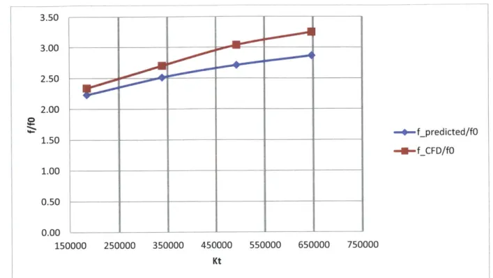
Ito [4] gives an experimentally-derived friction factor equation for the fully developed, laminar, rotating friction factor as
f 0.0883K4
1-1.969K t sf sfX
where
Kt = ReRn
and Rn is a dimensionless parameter known as the rotational Reynolds number defined as Ro =
(34)
(35)
(36) The equation was said to give good agreement with experimental results in the range Kt > 2 x
3.50 3.00 2.50-2.00 1.50__ --- f predicted/fO 1.50 -- f_CFD/fO 1.00 0.50 0.00 150000 250000 350000 450000 550000 650000 750000 Kt
Figure 4. Friction factor results obtained for rotating laminar, fully-developed flow in cylindrical tube for Re-1 ,200
Our data falls within the ranges recommended by Ito for the correlation to be accurate. As observed in Figures 4, the CFD model accurately predicts the friction factor as a function of the rotational speed.
5b. Nusselt Number-Rotating Reference Frame
The axial and circumferential distribution of mean temperature is found for the constant surface temperature condition by the equation.
d(Ts-Tm) irDh (TS s - TM) (37) dzde Thcp
In the rotating case, the heat transfer coefficient will now be axially and circumferentially dependent. Integrating Equation (37), we obtain
In hdzd (38)
ATi 2m cp o o The average heat transfer coefficient is thus
It =
fo
f
-zdxd6 (39)CFD simulations were run and corresponding Nusselt numbers for Re-1,200 and Re~2,000 as well as Rossby numbers, Ro- 4.1, 2.2, 1.5, 1.7 were obtained. Plots of velocity profiles at the
outlet for no rotation, slow rotation, and fast rotation for the case Re~ 1,200 as well as contours of velocity for these cases are shown in the Results section.
6. Results
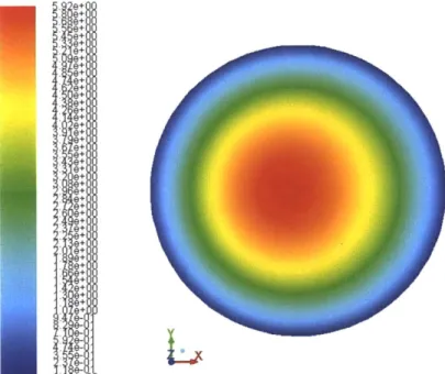
In the stationary fully developed laminar case, we observe the expected parabolic velocity profile. In the contour plot in Figure 5b, the core velocity at the center of the circular tube is highest and the flow is slowed down near the walls and zero at the walls by the no-slip
6.OUGUOU 5.00e+00 4.000+00 3.00+00 2.00e+00 -1.000+00 -0.00+00 0I- --0.003 -0.002 .***., 1. 0~ - . -0.001 0.001 0.002 0.003 Position (m)
Figure 5a. Cross-section at outlet of circular tube showing parabolic velocity profile in
stationary (i.e. no rotation) case
e+ e+8 e+8 e+ e+ e+8 e+ 8-e+
L
Figure 5b. Contours of z-velocity showing velocity distribution inside circular tube in non-rotating case condition. Relative Z Veloci (m/S) * 0 0 )
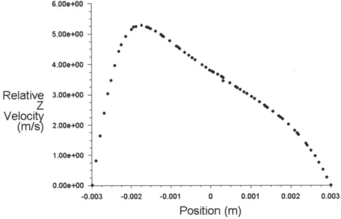
In Figure 6a with low rotation, instead of displaying the parabolic profile we expect in the stationary laminar case, the flow profile is shifted towards the trailing edge of the tube, away from the leading edge, resulting in an asymmetrical parabolic profile.
0 *0% -0% 0.00000# . .I -0.003 -0.002 1 0 Position (m) 0.002 0.003
Figure 6a. Cross-section at outlet of circular tube showing parabolic velocity profile shift for low rotational speed, n0= 60 rpm, for channel rotating counter-clockwise about the y-axis
Ie:
e+
0-Figure 6b. Contours of z-velocity showing velocity distribution inside circular tube in low-rotation case for channel rotating counter-clockwise about the y-axis. Flow is shifted against
trailing edge. *o0f 6.000+00 -5.00e+00 4.00e+00 -3.00e+00 -2.00e+00 -Relative z Velocit (M/ ) 0 1.000+00 -0.00 9. * 0.001 *... 0
At higher rotational speeds, more of the flow is shifted towards the trailing edge of the tube. As seen in Figure 7b, this causes more of the flow to be slowed down as there is less of a presence of higher velocity in the contour plot.
% 01. ***. 6.00e+00 -5.000+00 4.009+00 3.009+00 2.009+00 1.00e+00 0.00e+00 ' -0.003 0 'I 1 0 Position (m) 0.001 0.002 0.003
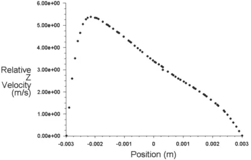
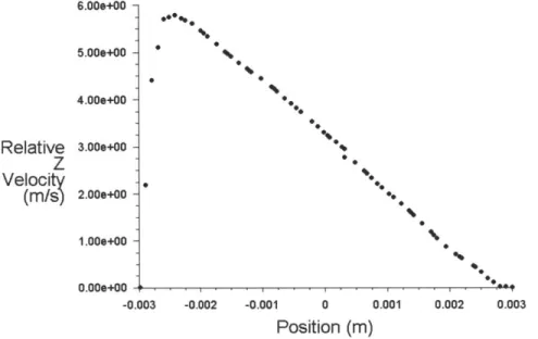
Figure 7a. Cross-section at outlet of circular tube showing parabolic velocity profile shift for rotational speed L0= 300 rpm for channel rotating counter-clockwise about the y-axis
5.38e+00 5.1 le+00 4,84e+00 4.57e+00 4 30e+00 4.03e+00 3.77e+00 3.50e+00 3 23e+00 2 96e+00 2.69e+00 2.42e+00 2.15e+00 1 88e+00 1 61e+00 1.34e+00 1.08e+00 8.079-01 5.38e-01 2.69e-01 0.00e+00
Figure 7b. Contours of z-velocity showing velocity distribution inside circular tube in rotation case Q0= 300 rpm for channel rotating counter-clockwise about the y-axis. Flow is shifted
against trailing edge.
* ~0 0 S %, Relative z Velocity (m/s) 0 -0.002 -0.00
At the high rotation rate, we see the most shift toward the trailing edge of the wall with the maximum of the velocity profile the furthest shift to the left of all the cases. In addition, from the contour plot, the flow is slowed significantly from the low-rotation case.
0 * 0* e0 -0.002 -0.001 0 0.001 Position (m)
Figure 8a. Cross-section at outlet of circular tube showing parabolic velocity profile shift for high rotational speed, 90= 2000 rpm, for channel rotating counter-clockwise about the y-axis
9+ e+ e+ e+ e+ e+ e+ 9+ e+ e+ e+8 e-e+8 e-e+
e-L
Figure 8b. Contours of z-velocity showing velocity distribution inside circular tube in rotation case 920= 2000 rpm for channel rotating counter-clockwise about the y-axis. Flow is shifted
against trailing edge.
6.00+00 -5.009+00 4.00e+00 3.00e+00 2.000+00 -Relative z Velocit (m/S) 1.00e+00 -0.003+00 -0.003 0.002 0.003 * ..
In the high rotation case, the secondary flow caused by the Coriolis forces arising in the rotating reference frame is the greatest of the three cases. Secondary flows caused by Coriolis forces are said to increase heat-transfer effects. The following analysis presents and discusses data
simulated for Re~1,200 and 2,000 and Ro~4.1, 2.2, 1.5, 1.7.
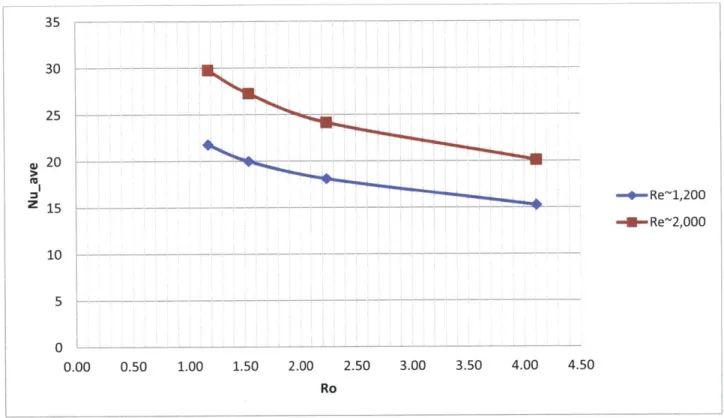
_35 - - - - -- --+-Re~1,200 -- Re~2,000 0.50 1.00 1.50 2.00 2.50 3.00 Ro 3.50 4.00 4.50
Figure 9. Average Nusselt number results obtained over length of tube for Ro- 4.1, 2.2, 1.5, 1.7 and Re~1,200, 2,000. Increased heat transfer effect with increased rotation can be seen.
The average Nusselt number is higher at a given Rossby number for higher Reynolds number. Increasing rotational speed for a given Reynolds number leads to enhanced heat transfer effects. In the range of 1.2<Ro<4.1 for both Re-1,000, 2,000, the average Nusselt number increases about 50%.
30 25 20 15 10 a, z 5 0 0.00
---
- - - - --- ----
---25.00 -20.00 -M -M -A r A w 15.00 - Ro=4.1 U URo=2.2 Z 10.00 --- - - - Ro=1.5 -M-Ro=1.2 5.00 - ~ - -0.00 0.00 10.00 20.00 30.00 40.00 50.00 60.00 70.00 80.00 z/D
Figure 10. Average Nusselt number obtained for axial positions for Re-1,200 and Ro-4.1, 2.2,
1.5, 1.7. Increased heat transfer with increased rotation speeds can be seen.
35 - -20 >20 - Ro=4.1 -1-Ro=2.2 z 15 - -- - - --r- Ro=1.5 10- - --- - - - - --- - - - -- Ro=1.2 5s - -- --- - - - - - ----0 0 10 20 30 40 50 60 70 80 z/D
Figure 11. Average Nusselt number obtained for axial positions for Re-2,000 and Ro-4.1, 2.2,
In Figures 10 and 11, the average Nusselt number obtained for axial locations throughout the tube for a given Reynold's number and Rossby number are reported. Increased rotational speeds (decreased Rossby number) lead to increased heat transfer effects. Between the graphs, it can also be observed that increased Reynold's number for a given Rossby number results in increased heat transfer effects.
30 1 -4-- Re~1,200 Z 15 ---- - -- - - - -Re2,000 10 5 0 20 30 40 z/D 50 60 70 80
Figure 12. Average Nusselt number obtained for Ro~1.2 for Re~1,200 and Re~2,000. Enhanced heat transfer at given Rossby number for a larger Reynolds number.
Figure 12 shows the average Nusselt number obtained for Ro~1.2 and Re~1,200, 2,000. Enhanced heat transfer over the length of the tube is seen for a larger Reynolds number.
Interestingly, the curves show a dip followed by an increase and plateau to a value at infinity. As seen in the stationary, constant wall temperature case, the coefficient of convective heat transfer is large in the entrance region and then decreases to a constant value in the fully developed region. In the rotating case, the Nusselt number first decreases, then increases, and finally plateaus to a higher value at infinity. The Coriolis forces due to rotation are interfering with the boundary layer development downstream so that increased heat transfer effects are seen
downstream.
U -4---- - -- --.---
----I---* Re~1,200 * Re~2,000 00 0.50 1.00 1.50 2.00 2.50 3.00 3.50 4.00 4.50 RoFigure 13. Ratio of heat transfer enhancement to friction losses
Figure 13 shows the ratio of heat transfer enhancement to friction losses as a function of the Rossby number which is of particular importance in cooling applications because it
quantifies the price which must be paid for heat transfer enhancement (i.e. increased friction losses) with increased rotation. The data shows the ratio of heat transfer enhancement to friction factor penalty is always greater than one for every rotational speed, meaning that at any
rotational speed, the heat transfer enhancement wins out over increased pressure drop. The ratio appears to remain fairly constant over the span of rotational numbers. This observation is consistent with the results seen in Figure 14, showing the ratio of heat transfer enhancement to friction factor as a function of Ro for the theoretical model. The theoretical model uses Mori and Fukata's [8] Nusselt number correlation and Ito's [4] friction factor correlation for 6.2<Ro<1.0 and Re~1,200. Over the span of Rossby numbers from for 6.2<Ro<1.0, the ratio shows about a 3% increase in value. 2 1.8 1.6 1.4 -1.2 -z 1 -o 0.8 Z0.6-0.4 0.2 -0
1.68 2. - - - --- - - - - h o e ia o e 1.6 -- - - -1.6 -> 1.21 o 2 4 5 6 7
Z1-ric d-4- Itoi and Fk and tukaa
oue 0.8 correlationTheoretical Model
0.4 - - ---- -- -- -- -- -- ---
--0.2 --
--0
0 1 2 3 4 5 6 7
Ro
Figure 14. Ratio of heat transfer enhancement to friction factor as a function of Ro for theoretical model developed using Ito's [4] friction factor correlation and Mori and Fukata's [8]
Nusselt number correlation for 6.2<Ro< 1.O0 and Re-A1,200
7.
Conclusion
Increasing rotation speed leads to increased heat transfer effects due to secondary flow caused by Coriolis forces. Rotation improves heat transfer from the stationary case by increasing heat transfer on the trailing edge of the channel compared to the leading edge, resulting in an overall increase in the convective heat transfer coefficient as well as an increase in the flow resistance from the stationary case. However, the data shows the ratio of heat transfer enhancement to friction factor penalty is always greater than one for every rotational speed, meaning that at any rotational speed, the heat transfer enhancement outweighs the increased pressure drop.
8. Bibliography
[1] B. M. Boubnov and G. S. Golitsyn (1995). Convection in Rotating Fluids. Springer, pp 5-10. ISBN 0-7923-3371-3.
[2] E. N. Sieder and G. E. Tate. Ind Eng. Chem., 28, 1429, 1936. [3] H. Hausen. Z. VDI Beih. Verfahrenstech., 4, 91, 1943.
[4] H. Ito and K. Nanbu (1970). "Flow in Rotating Straight Pipes of Circular Cross Section," ASME paper No. 70-WA/FE-13.
[5] Incropera et al (2002). Fundamentals of Heat and Mass Transfer. pp 465-490. ISBN
0-471-38650-2.
[6] W. D. Morris. "Rotating Facility to Study Heat Transfer in Cooling Passages of Turbine Rotor Blades," Proceedings of the Institution of Mechanical Engineers, Part A: Journal of Power and Energy 1996. online version: http://pia.sagepub.com/content/210/1/55.
[7] Whitaker, S., AIChE J., 18, 361, 1972.
[8] Y. Mori and T. Fukada. "Convective Heat Transfer in Rotating Radial Circular Pipe (2nd