THE CRYSTAL STRUCTURE OF NEPHELINE by
GILBERT ENGLANDER KLEIN B.S. in Physics,
M.S. in Physics,
Case School of Applied Science, Case School of Applied Science,
1939 1942
SUBMITTED IN PARTIAL FULFILLMENT OF THE REQUIREMENTS FOR THE DEGREE OF
MASTER OF SCIENCE at the
MASSACHUSETTS INSTITUTE OF TECHNOLOGY 1947 Signature Certified
Signature redacted
of Author . ... Crystallography Laboratory Department 0f Geology, May by: ...Signature redacted
JThesis Superxvisor
20, 1947
* 04 * *90* 0 . *
Signature redacted
v wv ww 9 9 9 v w w w w WW999 v w 9vv909vv99vv&99 00Com . on Graduate Students
*. .* 0.*.*
r
THE CRYSTAL STRUCTURE OF NEPHELINE
by
3S
TABLE OF CONTENTS
Acknowledgements
Chapter I - Introduction... 1
Chapter II - Previous Work on Nepheline ... 3
Chapter III - Experimental Work (Part I) ... 13
A. - Selecting the Crystal ...13
B. -Obtaining the Negatives ... 14
C. -Obtaining the Positives ... 16
1. Theoretical Considerations ... 16
2. Actual Procedure ... 17
D. - The Measurement of Intensities ... 22
E. - Correcting the Data ... 27
F. - Experimental Data and Computations ... 29
Chapter IV - Experimental Work (Part II) ... 37
A. - Space Group Data ... 37
B. - Preliminary Considerations ... 38
C. - Implication Diagrams ...41
D. -Electron Density Maps ... 46
E. - Theoretical Intensity Calculations ... 53
1. Introduction ... 53
2. Application and Results ... 55
F. - Discussion of the xy Parameters ... 64
Chapter V - Experimental Work (Part III) ... 66
A. - Preliminary Reasoning ... 6
~mw T
C. - Calculation of Structure Factor
Components ... 72
D. - Electron Density Projections ... 85
E. - Planar Sections ... 89
Chapter VI - Discussion of Results ...97
Appendix Computational Forms and Data Used for Performing the Various Fourier Syntheses ...
101
A. - Introduction ...
101
B. - Harker Synthesis P(xyO) ... 105
C.- Harker Implication I6(xyJ) ... 105
D. - Electron Density Projection (xy0)...,106
E. - One-Dimensional Harker Projections P(xlylz) ... ,...107
F. - Electron Density Projection ,(x12xiz).108 G. - e(xyi) Section ... .112
H. -e(x0z) Section ... 116
I. - e(xyO) Section ... 9.117 J. - e(x, 2/3, z) Section ... 118
LIST OF ILLUSTRATIONS
Fig. 1 The Printing Box
Fig. 2 - Diagram of Intensity Measuring Apparatus Fig. 3 - Set-up for Intensity 1easurements
Fig. 4 - Elements in Space Group C63 (H63 ) Fig. 5 - Data from Harker Implication I3(xyO) Fig. 6 - Harker Implication I3(xyO)
Fig. 6a - Harker Synthesis P(xyO)... Fig. 7 - Data from Harker Implication I6(xyj)
Fig. 8 Harker Implication I6(xy).
Fig. 9 - Data from Electron Density Projection ((xyO Fig. 10 - Electron Density Projection e(xyO) ... Fig. 11 One-dimensional Harker Projections P(d--z). Fig. 12 - Projection of the Idealized Nepheline
Structure along the C-axis
Fig. 13 - Forms for Computing A and B Components
of the Structure Factor ...
Fig. 14 - Data from Electron Density Projection e(x12xiz)
Fig. 15 - Electron Density Projection q(x12xyz) ... Fig. 16 - Expected Atom Positions in e(xOz) Section . Fig. 17 - Expected Atom Positions in (xyo) Section .
19 23 25 39 43 44 45 51 52 )61 62 69 71 74 87 88 92 93
Fig. 18 - Expected Atom Positions inC(xy ) Section . 94 Fig. 19 - Expected Atom Positions in V(x12xlz)
Section ... 95
Fig. Al - Calculation Forms ... 102
Fig. A2 - Schematic Form of Computation for Non-Centrosymmetrical Sections and Electron
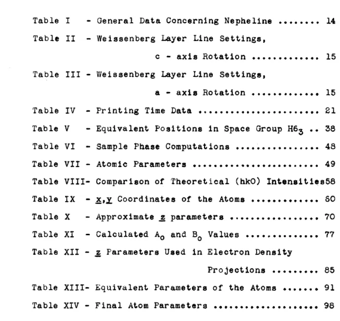
LIST OF TABLES
Table I - General Data Concerning Nepheline ... 14
Table II - Weissenberg Layer Line Settings,
c - axis Rotation ... 15 Table III - Weissenberg Layer Line Settings,
a - axis Rotation ... 15 Table IV - Printing Time Data ... 21
Table V - Equivalent Positions in Space Group H65 .. 38 Table VI - Sample Phase Computations ... 48
Table VII - Atomic Parameters ... 49
Table VIII- Comparison of Theoretical (hkO) Intensities58
Table IX - x,x Coordinates of the Atoms ... 60 Table X - Approximate z parameters ... 70 Table XI - Calculated AO and BO Values ... .... 77
Table XII - z Parameters Used in Electron Density
Projections ... 85
Table XIII- Equivalent Parameters of the Atoms ... 91 Table XIV - Final Atom Parameters ... 98 -. 1 1, 1 'M
ACKNOWLEDGMENTS
The writer wishes to acknowledge the support given by the Owens-Illinois Glass Company during the duration of the project. Without this financial
backing, the project would never have been possible. To Professor Martin J. Buerger, who first suggested the problem and who acted as the guiding spirit, especially when the progress seemed to reach its lowest ebb, I wish to express my sincerest thanks for his understanding and interest in the problem at all times.
The aid given by Miss Gabrielle Hamburger, who for a time worked on the project and performed many of the calculations as well as offering many valuable suggestions, helped greatly in the performance of the work. Mrs. Elsa Barney added her efforts to the
comple-tion of the work with the preparacomple-tion of several of the illustrations.
Lastly, I should like to acknowledge the aid given by my wife, Mrs. Ann S. Klein, who helped me at various times with the performance of various tasks during the progress of the work and who acted to lend moral support when it was needed the most.
Chapter I INTRODUCTION
In spite of the large amount of work which has been done on the silicate minerals, Braggi points out that there are still a number of structures which are assumed to be composed of linked silicon-aluminum-oxygen tetrahedra which have not been thoroughly igvestigated up to the present time. Nepheline is one of this group of minerals.
Although a fair amount of preliminary work had been done on nepheline, including the determination of the unit cell dimensions and other physical constants,
and Schiebold2 went so far as to suggest that the structure of nepheline is based on the structure of tridymite, the actual determination of the structure still remained a real trial due to the complexity of the problem and the lack of sufficiently powerful and appli-cable methods of analysis.
With this background in mind it was decided to undertake the problem of determining the arrangement of the atoms in nepheline. The results which would be forthcoming would then give definite information con-cerning the packing arrangement of sodium and data as
to the silicon-oxygen and aluminum-oxygen distances. Since it became necessary to work out a new method of attack for the analysis of the structure of nepheline, an attempt was made to keep the method so
general as to be applicable to all structures of this type.
Chapter II
PREVIOUS WORK ON NEPHELINE
The mineralogical and morphological properties of nepheline are well known and may be found in all standard textbooks on mineralogy3.
The earliest reference to work directly concerning nepheline appears in two articles by H. Baumhauer4 ,5
appearing in 1882 and 1891. As early as 1892, Andre Duboin6 ,7 synthesized potassium-nepheline crystals which
crystallized as orthorhombic prisms.
As a result of etch-figure methods, Baumhauer8 (1894) assigned nepheline to the hexagonal-pyrimidal class. Using
both dilute hydrofluoric acid and hydrochloric acid as etchants, he obtained undisputable evidence for assigning nepheline to the above class, and the photomicrographs which he presents easily show the only symmetry to be a six-fold hexagonal axis.
Bowen and Elestad9 report the findings of Dr. J. Morozewicz 10 (1897) to the effect that the mineral
nephe-line has a constant composition whatever the rock in which it is formed, the fixed composition represented by the formula K2A128i3010 * 4 Na2Al2Si2O8' Bowenil
main-tains, on the contrary, that nephelines are responsive in composition to the magmas from which they form, those
occuring in the potash-rich rocks of one region should differ in a definite manner from those occuring in the soda-rich rocks of another region. He concludes that nepheline is made up of pure soda nepheline with a kaliophilite molecule and two plagioclase molecules,
albite and anorthite, in solid solution. The composi-tion reported is then Na8Al8Si8O32*
Bannister1 2 states that the occurance of nepheline as well-formed crystals is restricted to comparatively
few localities, although as the massive variety, elaeolith, and more generally as a rock-forming mineral it is very widely distributed. According to Bowen and Grieg13 the compound NaAlSiO4 is stabile below 12480C. as a hexagonal form corresponding with nepheline and above this tempera-ture as a triclinic form with lamellar twinning which has been called carnegieite.
Gottfriedl4 (1926) found as a result of his investi-gations on a nepheline crystal from Vesuvius that nephe-line crystallizes in the hexagonal-tetaroedral system in crystal class C6 and gave the following measurements.
a:c
=
1:0.839 where a=
10.09 A.c
=
8.49 A.From the identity period, the molecular weight of nepheline (S104)01, which is 146.0 and its density, 2.60, he found
the contents of the elementary cell, V
=
749 Af, and the number of molecules in the unit cell, Z=
8.08. Hence, there are 16 molecules in the orthohexagonal unit cell, of which there are 16 Na, 16 Al, 16 Si, and 64 0 atoms. The assigned space group is Cg - C63.Gossnerl5(1927) disagrees with the findings of Baumhauer and states that not all of the physical proper-ties of nepheline are in accord with placing it into the hexagonal-pyrimidal class. He claims that the dihexagonal-dipyrimidal class will give full agreement with the physical
properties and that if one insists ou placing nepheline
in the pyrimidal class, then the space group Cg - C63 is the only one giving the even orders of the (0001)
reflec-tions which the x-ray data presents. Gossner, however, 6
rules out the space group C6 - C63 on the basis that the ratio of the number of atoms with individual symmetry to the number of atoms without individual symmetry is too small.
Even though the dihexagonal-dipyrimidal class is in agreement with the physical properties of nepheline, the only symmetry shown by Laue photographs is a six-fold axis, and hence this class must also be ruled out. The space group C - C63/m of the hexagonal-dipyrimidal class does, however, agree with existing x-ray data and permits a more satisfactory arrangement of atoms than does C8 - C63, and it
4
is to this space group which Gossner assigns nepheline. He gives as the formula for nepheline Si205Na2*A1203, and gives for the parameters:
PLool] * c axis 8.37 - 8.48(Average
=
8.4310-8 cm.) PLOlO] = a axis 10.08-1O.12(Average
=
10.09 *10-8 cm.) a:c 1: 0.8389
Z :4
The unit cell contains 8 Si, 8 Al, 8 Na, and 32 0 atoms. Gossner also compares nepheline with chrysoberryl and olivine, and although there is a slight similarity
in axial ratios, there is no close similarity in the
parameters and in the other properties of the three minerals. Both Gottfried and Gossner discuss the various ways of arranging the atoms of the unit cell and each concludes
independently that there must be 2 Si, 2 Na, 2 Al, and 8 0 atoms in the special positions and 6 Si, 6 Na, 6 Al, and 24 0 atoms in the general positions.
Jaeger, Westenbrink, and Van Melle1 6(1927) inves-tigated crystals of nepheline from Monte Somma and con-firmed the existence of the hexagonal unit cell belonging to the space goup C8 - C63, the rhomb-based cell containing 8 NaAlSiO4 and having edges, a
=
9.87 A. and c=
8.38 A.. In a subsequent paper17 Jaeger confirms this earlier work by his co-workers and himself.Schiebold2,l8(l930,l93l) studied nepheline samples obtained from Parco Chigi and found the crystals to have
a = 10.1 A., c
=
8.51 A., where the unit cell contained 8 molecules of NaAlSiO4 and belonged to the space group C6 C63. Schiebold concludes that the structure is not close-packed hexagonal, but shows a close resemblance to that of tridymite with [Sio4l
and [A1041 groups, thus explaining the usual excess of silica in nepheline. The pseudo identity period a' of nepheline=
5.05 A., and tridymite has a = 5.03 A..Schiebold presents a suggested picture for the structure of nepheline based on the tridymite structure in which silicon and aluminum atoms are located on the special position 3-fold axes and are surrounded by oxygen atoms in tetrahedral arrangement, while alternating silicon and aluminum tetrahedra are located in the general posi-tions and join on to the special position tetrahedra. Two Na atoms are then located one above the other (in the Z direction) either on the 63 or the 2-fold serew axes, and certain sodium atoms may be replaced by Ca atoms according to this picture which Schiebold presents.
Bannister and Heyl2(1931) have made the most inten-sive study of nepheline, investigating some ten different samples from various localities for chemical, optical, and x-ray properties. They took over forty previous chemical
analyses of nepheline made by various workers and put the results in a common form. Of the ten samples investi-gated, six were from Monte Somma. All samples showed hexagonal symmetry and were represented by the simple formula NaAlSiO4 , although the chemical analyses proved
the silica content to be greater than that indicated by the simple formula and showed some potassium to be present.
The following data was reported by these workers: a 9.96 - 9.99 A. 4C 8.31 - 8.38 A. c/acalc. 0.835 - 0.840 c/ameasured 0.834 - 0.8385 Density 2 2.591 - 2.647 W.
=
1.5299 - 1.5461 E=
1.5264 - 1.5422 vW-6 = 0.0028 - 0.0037Number of 0 atoms per unit cell 3 31.6-32.4 Si content range, 7.99-9.03 (Aver. = 8.50)
Al 6.94-8.13 7.50 Ig 0.00-0.23 0.03 Ca 0.00-0.52 0.35 Na 5.04-7.57 6.20 K 0.22-2.57 1.25 Si Al 15.79-16.20 16.00 remainder 6.91-8.61 7.60
r
From the above data Bannister and Hey concluded that the unit cell of nepheline may be more correctly written as Si16-nAn(NaK,}Ca)nO3 2, where n varies from 6.6 to 8.2.
The values of a2c as calculated from the forty chemical analyses reported by other workers which were accompanied by density data, range between 822 and 852 A*, while Bannister and Hey obtain values of 824-846 from
their chemical analyses and values of 821.5-837 obtained from x-ray data.
The Laue symmetry was found to be C6h - 6/m with a space group of C8 - C63. The authors state, following that given by Schiebold, "The rhomb-based cell contains 4 3i02 and the structure consists of linked tetrahedra of silicon surrounded by 4 oxygen atoms. If half the silicon atoms be replaced by aluminum, the structure
becomes polar. The disappearance of the vertical planes of symmetry might be explained in terms of a rotation of each tetrahedron of Si and 0 and Al and 0 atoms about the trigonal axis, but this would not account for the a dimen-sion now being doubled (that for tridymite). A plan of the structure perpendicular to an a dimension also shows obvious gaps for the alkali atoms, but symmetry conditions are not sufficient to fix either the exact position of the oxygen or the alkali atoms.
10~
on the trigonal axes and the alkali atoms are probably situated on or around hexad axes. The gaps in the structure which accomodate the alkali atoms are about the diameter of 0 atoms, i.e. 2.5-2.7 A., where Na = 2.0 and K
=
2.6 A. respectively."One of the specimens studied by Bannister and Hey was a sample of pseudo-nepheline from Capo di Bove near Rome having a high potassium content. The x-ray photo-graphs of this sample were typical of the Monte Somma nepheline and showed the pseudo-nepheline to have the same axial ratios.
Eitel and his co-workers1 9(1950) investigated synthetic minerals similar in composition to nepheline by optical and x-ray methods and found the nepheline-type minerals to be hexagonal, doubly refracting optically
negative crystals. For the nepheline-like crystals they found a= 9.95 A. and c= 8.42 A.. Jaeger and his
co-workers16 also studied powder diagrams of synthetic nepheline preparations and found them to give patterns
identical with those of natural nepheline.
More recently Nowacki2 0(1942) has studied the
relation between several of the silicates and has found
for nepheline that it bears a close relation top- tridymite as shown by the following:
~A~i
Nepheline 9- Tridvmite a 5.05 A. a=
5.03 A. c :8.49 A. c=
8.22 A. Z :8 Na(AlSiO4 ) Z :2 S104 3 3 MV=
54.7 cm* MV=
54.58 cm. d=
2.60 gem* d : 2.20 gcm-3The space group of nepheline, C - C63 is a sub-group of the space group ofP- tridymite, D6h - 06/me.
The comparison was next carried out between nepheline and kaliophilite. Nowgcki found that the difference in the cell for the two crystals pointed to a difference in structure. He pictures the rhomb-based cell of nepheline as containing tetrahedra alternating in space, every other one with its summit pointing up, the alternate tetrahedron with its summit pointing downward. The tetrahedra in the
kaliophilite cell are pictured on one level as being similar in spacial positioning with the next level containing
tetrahedra rotated 1800 in the horizontal plane and the summits all pointing in the opposite direction.
Belov2 1 reports on the structural (statistical) formula of nepheline as being similar to that of)?- tridy-mite in which half of the SiO4 tetrahedra are replaced by A104 , and he contrasts the structural data with the 'nuclear'
formula derived from chemical considerations and concludes by explaining their mutual relationship.
14
Almost all of the more recent work on nepheline has been concerned with the massive and rock-forming varieties and not with nepheline single crystals. This work has deal4 mainly with its properties, such as fluores-cence, viscosity, conversion temperature, origin, petro-logical conditions, uses in glass manufacture, etc..
Winchell2 2 attempted to solve the problem of the chemical composition of nepheline and its correlation to the physical properties, but could find no correlation.
It-J
Chapter III
EXPERIMENTAL WORK (Part I)
The analysis or determination of any crystal structure depends first of all on being able to obtain complete and accurate data. The present chapter is
concerned with the methods followed and apparatus employed in fulfilling this end. Since several of the methods and some of the equipment used were purposely designed or adapted for the first time for the purpose of this investi-gation, they will be described in complete detail.
A. - Selecting the crystal
Since the method to be employed was to use a beam of monochromatic x-rays and a single crystal, the first task was to obtain a truely single crystal of nepheline of suitable dimensions for x-ray crystallographic analysis. This proved to be a somewhat arduous task first, because the available supply of nepheline crystals of suitable dimensions proved to be very scarce, and secondly, because most of the available supply proved to be twinned crystals.
The crystal which was finally selected for the examination was a specimen from Monte Somma, Vesuvius, obtained through Dr. Fredrick H. Pough from the American Museum of Natural History. Since the crystal proved to be
MOW-14
too thick for use it was necessary to carefully split off a fragment which was to be used in all the subsequent
investigation.
The fragment was mounted and adjusted to a goinio-meter head using a two-circle optical goiniogoinio-meter for all adjustments. For the first part of the work the crystal was mounted so that it would rotate about its c-axis
direction. In subsequent work the crystal was mounted with the a axis as the rotation axis.
B. - Obtaining the negatives
The -experimental techniques used to obtain the x-ray negatives and analyze them closely followed those presented in X-RAY CRYSTALLOGRAPHY2 3.
Rotation photographs were made about the c-axis direction and the a-axis direction. The information
obtained from these photographs enabled the calculation of the dimensions of the unit cell. From this
informa-tion it was possible to calculate the reciprocal lattice dimensions and consequently the settings required for making the Weissenberg photographs. Tables I - III present such data.
Table I - General Data Concerning Nepheline c
=
8.38 x 10⁻⁸ cm. c*=
.1837 A/C a = 9.99 x 10'8 cm. a*=
.1778 2 A /a c/a = 0.8388Table II
-co:
.000 .183 .366 .549 .732 .915Weissenbera Laver Line Settinap c-axi rotation -. 0.00 5.3 10.6 15.9 21.4 27.2 0.Omm. 2.3 4.6 7.2 10.0 13.1 Cos A 1.00000 .99572 .98294 .96174 .93106 .88942 coo2 1.000 .992 .966 .925 .867 .790 20 cos2 U 20.00 hours 19*84 19.32 18.50 17.34 15.80 Table III S: a* .000 .178 .356 .534 .712 .890 1.068 - Weissenb 0.00 5.1 10.3 15.5 20.8 26.4 32.3 erg Layer A 0. Omm. 2.2 4.7 7.1 9.7 12.7 13.2 c I
Line --set tinge j, a-axris rotation
os A 0082 A
20
o21 .00000 1.000 20.00 hours .99604 .992 19.84 .98389 .966 19.3Z .96363 .930 18.60 .93483 .874 17.48 .89571 .803 16.06 .88862 .714 15.80 Laver_# 0 1 2 3 4 5 Layer # 0 1 2 3 4 5 6-I
-T1it
Weissenberg photographs of the various levels were then made using the Weissenberg camera with the crystal mounted first for the c-axis rotation and then for the a-axis rotation. The exposure times employed for the individual layers as calculated in the last columns of
Tables II and III take into account an automatic correction for the time-Lorentz factor according to the scheme out-lined by Buerger2 4 ,25 and Klein2 5, thus making it
unneces-sary to correct for this factor in the latter calculations. The negative films were then processed according to the quantitative scheme to be discussed in the following section. All Weissenberg exposures were made on Eastman No-Screen X-Ray Film using copper radiation from a Machlett tube monochromatized through a rock salt monochromater, the tube being operated at 30 kv. and 15 ma..
C. - Obtaining the po.itives
1. Theoretical Considerations
-One of the greatest problems in analyzing crystal structures by x-ray methods up to the present time has been the determination of the intensities of the various x-ray reflections recorded on the film. Dawton2 6 devised a photographic scheme for transforming the opacity of
x-ray spots to transmissive spots, the resulting trans-missions being directly related to the opacity which
-MAW"Mm"imlim-it
d
originally occurred. Since it is more convenient and more accurate to measure transmission of light than to measure the opacity to light, it was decided to expand and modify the Dawton technique where necessary so as to be applicable to the present problem in particular, and to other problems of the same kind in general.
In order to obtain the above desired results it was necessary to devise several new pieces of apparatus
and new techniques which would be both accurate and completely reproducible. They are as discussed in the following pages.
2. Actual Procedure
-The Dawton method involves finding a negative photographic material which with a particular processing technique will give a photographic curve matching that obtained from a positive photographic material also
processed in some suitable manner. It is also necessary to find, as part of the procedure, a satisfactory method for transmitting the print of the negative on to the
positive material; this involves finding the correct condi-tions of light and time of exposure in the printing process.
After considerable experimental groundwork, a set of photographic materials with the appropriate techniques for handling them were found, these giving a satisfactory photographic match as desired. The actual choice of film
ILO
materials and conditions for processing these films had been previously investigated and worked out by Mr. John Tyler -(unpublished work).
Employing the results found by Mr. Tyler, it became necessary to expand and modify these so as to be put on a more permanent basis. He found that Eastman No-Screen Film developed for 8 minutes at 650F. (for copper radiation) in Eastman D-76 developer to which
.1r KBr and 14 KI solution had been added used with
Eastman Commercial Orthochromatio Films developed for 3 3/4 minutes at 650F. in Eastman DK-50 developer gave a
set of matching films when exposed under certain printing conditions. It was these printing conditions which it
became necessary to standardize and put on a more suitable and useable basis.
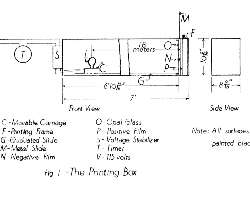
(a). The Printing Apparatus
-The printing apparatus as constructed is diagrama-tically illustrated in Fig. 1. It consists essentially of a light source located on a carriage capable of moving along a graduated slide, a printing frame for holding the negative and positive films, and an automatic exposure timer for controlling the time of exposure. The light source and film holder are located inside of a light tight box painted black on all surfaces.
T
s
C
-
Movab/e
Carriage
F
-Printing
Frame
G -Grcoduated 5liJe
M-!Metdl Slide
N-
Negative
Film
M
F
6'1oJ
71
Front Vi ew
0-Opal
GlassP
-
Positive
Film
5
- Voltage Stabilizer
T
- Timer
V- 115 volts
0
BI
I
Side View
Note:
All urfaces
painted
Fig.
1
-The Printing
Box
are
black.
The light source consists of a clear 6-watt light bulb which had been previously seasoned so as to provide a constant output. The candle power of the bulb is
3.112 horizontal candle power at a distance of 1.8 meters from the film. To aid in maintaining a constant output, the power is supplied from a 115 volt Raytheon type
VR-307 voltage stabilizer. Baffles are placed at
appropriate positions inside of the box to prevent light scattered or reflected from any part of the box or auxil-liary equipment from reaching the film. The front of the printing frame is provided with an opal glass having a transmission filter factor of .242 so as to allow uniform illumination to fall on the film surface. In front of the opal glass there is a metal slide which enables the entire printing frame to be removed or placed in position the daylight. The automatic exposure timer is a model P-lIM Reset Timer manufactured by the Industrial Timer Company.
(b). Method Used
-The negative film (which had been quantitatively processed as previously discussed in Eastman D-76 developer
to which KI and KBr solutions had been added and had been developed in a tank for the appropriate time as listed in
Table IV with constant agitation of the film and then fixed in Eastman X-Ray fixing solution, washed, and dried) is
41
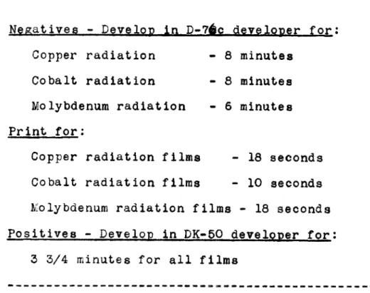
Table IV - Printing Time Data
Negatives - Develop in D-7jc.developer for:
Copper radiation - 8 minutes Cobalt radiation - 8 minutes Molybdenum radiation - 6 minutes
Print for:
Copper radiation films - 18 seconds
Cobalt radiation films - 10 seconds
kolybdenum radiation films - 18 seconds Positives - Develop in DK-50 developer for:
3 3/4 minutes for all films
-- --- ---placed in the printing frame in contact with a sheet of Eastman Commercial Orthochromatic film, and the printing frame is then dropped into its slot in the printing box. The automatic timer is then set for the correct exposure time as listed in Table IV and the exposure is made.
The film holder is then removed and the Commercial Orthochromatic film developed for 3 3/4 minutes in Eastman
DK-50 developer at 65 0F. with constant swabbing of the
emulsion surface so as to insure uniform development. The film is then fixed in regular fixing solution (not x-ray
fixer, which fails to remove the red dye base of the ortho-chromatic film), washed, and dried.
for all the levels.
D. - The measurement of int-ensities
It was necessary to index each of the films in complete detail according to the standard practices. After each reflection had been indexed, the next problem was to measure the intensities of these spots (meaning reflections).
In order to perform the above task it became neces-sary to devise and build suitable equipment to do the work since no such equipment was commercially available.
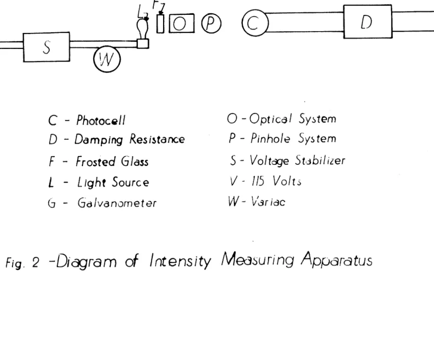
(a). The Intensity Meter
-The essential parts of the intensity meter are diagramatically illustrated in Fig. 2.
The voltage which is supplied to the light source (various wattage toy-projector bulbs are used for the light source depending on the amount of illumination required)
comes from a 115 volt type VR-307 Raytheon voltage stabilizer to insure uniform power output, hence uniform illumination, at all times. A General Radio Variac, type 200B, is pro-vided in the circuit so that any level of desired brilliance may be obtained. The light beam then passes through a
3/8 inch slab of Libbey-Owens-Ford heat resisting glass
frosted on both sides, which is placed in front of the light beam to insure a uniform beam and also to obsorb the heat
D
(5
C
-Photocell
D
-Damping
Resistance
F
-
Frosted
Glass
L -
Light
Source
(i
- Gd Ivanorneter
o
-
Opt ical
P
-
Pinhole
System
System
S
-
Voltage
Staibilizer
V -
115 Volts
W.-
'Vri.c
Fig. 2
-Digram
of Intensity Medsuring
Appara
tus
F
02
@1
-- ~-
~-~-rays generated which might burn the film. An electric fan is placed in back of the entire system to help conduct the heat away from all parts of the system.
The lens system next converges and focuses the light beam on to the pinhole system. Interchangeable pinholes of various diameters and slits of various sizes and widths are available for use depending on the size and shape of the spot to be measured. The light then falls on the spot for which a measurement is desired and the amount of transmitted light then falls on a Weston type 3, model 594 RR Photronic Cell.
The energy falling on the photocell is next recorded on a Leeds and Northrup type R galvanometer. A critical damping resistance is in series with the galvanometer to provide for damping the galvanometer so as to give it the highest sensitivity with the lowest possible period.
In actual use the light source, lens system, Variac, and photocell are all mounted on a specially designed
instrument housing (see Fig. 3). A bar, which is slotted alog its upper edge, carries the film to be measured and is attached to the housing at the right in such a way that it may be raised or lowered vertically so as to move the film up or down. The front panel is sloped and the
instru-ment built to such a height as to be convenient for anyone using the apparatus both as to ease of manipulation and
/
Fig. 3 - Set-up for Intensity Measurements
;Adt6
accessibility of observation. The photocell is mounted on a hinged arm which may be raised from the front panel to permit setting the film in its proper position.
(b). Manner of Using
-The positive film is set on the slotted bar and adjusted so that the most transmissive spot on any film of a related series is completely bathed in the light coming through the pinhole. This requires selecting a pinhole slightly larger than the labgest spot on any film of the related series. The Variac is then adjusted so that the spot in question causes a galvanometer deflection which is a maximum on the galvanometer scale. This spot will hereafter be used for standardizing all subsequent films of the same series so as to put all films from the same set on a uniform basis. It is understood, of course, that once a pinhole is selected according to the above
procedure, this pinhole is used for all subsequent work on the particular series of films in question.
Every spot on each film is then measured in turn. The transmission of each spot is first measured and the transmission of the film background right adjacent to the spot is then measured. The difference between the two transmissions gives the net transmission for the spot being considered.
scale, but are all to the same scale for any series of films, thus rendering all readings of a series comparable. The above requirement is all that is necessary in order to obtain useable intensity data.
E. - Correcting the data
The results of the above measurements give the values for Iobserved corresponding to each reflection. These values must be corrected for Lorentz and Polariza-tion factors. Since the Lorentz time-scale factor was taken into account in the timing of the various Weissenberg negatives it becomes unnecessary to correct for this factor.
The Lorentz-Polarization factor for the two differ-ent cases, that of the zero level and that for all levels other than zero, takes the following forms:
_1~, 2 sin-20 Zero level --- Lp' 1+ cos'20
Levels other than zero -- -. sin
T.
2Lp. 1+ cos29
Tables25 have been published giving completely
2 sin 29 and 2 as a function of sin 9 in 14- cos"2 G 1 + co sr29
arguments of *001 and of T in arguments of .002. The value of o is equal to 2 sin 9.
The vertical linear measurement, xof any Weissenberg photograph is directly proportional to the reflection
azimuth.T, wherel is equal to a function which is depen-dent on the constants of the instrument. Due to the
standardization of these constants on the Weissenberg instruments, the angle T: can be read directly in milli-meters by merely measuring the vertical distance, 2x, of the spot from the center line of the film.
It is thus possible to easily calculate the correction factor for any reflection if the value of either T or sin 9
for the reflection are known. For the case of nepheline (hexagonal system) the following condition prevails:
s in 9 6/2
=
a*2(h2+ k2+ hk)- ; c*2where a* and c* are the dimension of the reciprocal cell.
By means of the above, the values of sin Q and c-were calculated for each reflection (it is necessary to
calculate for only one of the two, either sin 0 or 6 )
and the corresponding value of the correct form of the Lorentz-Polarization factor was then determined from the
previously mentioned tables.
The complete data and computational results'are
presented in the next section. Wherever possible the data from the c-axis rotation films are used. Each value of Iobserved represents an average of all the equivalent spots
F. - Experimental Data and Reflection or 200 300 400 500 600 700 900 10.00 12*00* 110 210 310 410 510 710 810 910 120 220 320 420 520 720 920 130 230 330 530 830 930 140 240 640 740 840 150 250 350 550 650 750 .3549 .5329 .7113 .8894 1.0672 1.2450 1.6009 1.7788 .3081 .4706 .6413 .8151 .9904 1.3431 1.5199 1.6968 .4706 .6162 .7754 .9412 1.1109 1.4560 1.8053 .6413 .7754 .9243 1.2450 1.7519 1.9241 .8151 .9412 1.5508 1.7155 1.8826 .9904 1.1109 1.2450 1.5405 1.6968 1,8571 Com~utat ion8 I(exper.) 1/L*p .3717 .5903 .8547 1. 1681 1.5246 1.8653 1. 7806 1.2177 .3191 .5099 .7457 1.0311 1.3654 1.9724 1.9294 1.5083 .5099 .7077 .9606 1.2692 1.6095 1.9893 1.1101 .7457 .9606 1.2338 1.8563 1.3142 .6094 1.0311 1.2692 1.8829 1.4413 .7987 1.3654 1.6095 1.8563 1.8997 1.5083 .9001 1.2 5.3 1.1 .4 .5 .2 1.1 .2 .5 4.6 .6 .9 .2 .1 .2 .1 1.7 2.9 .7 .9 2.0 .1 .2 1.9 .1 .2 .4 .2 1.1 .2 .7 .3 .1 .4 .9 3.7 .4 .4 .2 .4
* Obtainable only on films made with molybdenum radiation A~j F2 .4 3.1 .9 .5 .8 .4 2.0 .2 .9 .2 2.3 .4 .9 .3 .2 .4 .2 .9 2.1 .7 1.1 3.2 .2 .2 1.4 .1 .2 .7 .3 .7 .2 .9 .6 .1 .3 1.2 6.0 .7 .8 .3 .4
Com utations
Reflection T 260 460 560 660 170 470 570 770* 180 380 480 190 290 390 3-10*0* 1.2826 1*5508 1.6968 1.8485 1.3431 1.7155 1*8571 1.5199 1.7519 1.8826 1.6968 1.8053 1.9241 1/L p 1.9073 1.8829 1.5083 .9416 1*9724 1.4413 .9001 1.9294 1.3142 .7987 1.5083 1.1101 .6094 Reflection .. _ 201 301 401 501 601 701 111 211 311 411 511 121 221 321 421 131 231 331 431 531 731 141 241 341 641 841 151 351 .4012 .5648 .7348 .9083 1.0831 1.2586 .3585 .4744 .6670 .8355 1.0070 .4744 .6429 .7967 .9589 .6670 .7967 .9423 1.0977 1.2586 1.5919 .8355 .9589 1.0977 1.5617 1.8916 1.0070 1.2586 1.0840 1.1715 1.3040 1.4865 1.7091 1.9164 1.0661 1.1186 1.2742 1.4053 1.6103 1.1186 1.2267 1.3635 1.5470 1.2472 1.3635 1.5274 1.7274 1.9164 1.8667 1.4053 1.6129 1.7274 1.9077 1.2317 1.6103 1.9164 I(exper.) .3 .3 .2 .3 .1 .1 .4 .2 .4 .4 .2 .2 1.1 sin .3600 .5090 .6704 .7997 .9056 .9755 .3107 .4617 .6060 .7385 .8643 .4617 .5906 .7181 .8329 .6060 .7181 .8171 .9078 .9736 .9686 .7385 .8329 .9078 .9796 .6374 .8643 .9736 I~exper.) 4.1 .1 .2 .8 .1 .2 .4 .2 1.6 .2 .3 .8 .3 .3 .2 1.0 1.0 .1 .2 .1 .2 .3 .3 .2 .2 .2 .3 .3 .6 .0 .3 .3 .2 .1 .4 1.1 .4 .5 .3 .3 .2 .7 ,9 ,2
--
t
1.6 .1 .2 1.0 .2 .4 .1 .1 1.2 .2 .4 .4 .2 .3 .3 .8 1.0 .1 .3 .2 .4 .3 .4 .3 .4 .2 .4 .6Reflection d 751 461 571 481 002 102 202 302 402 502 702 10*02 11*02 212 312 412 512 612 712 812 912 122 222 322 522 722 922 132 3.32 432 532 732 932 242 342 442 642 842 152 252 352 452 552 752 162 262 1.8663 1.5617 1.8663 1.8916 .3666 .4074 .5113 .6476 .8002 .9620 1.2977 1.8160 1.9905 .5966 .7387 .8938 1.0559 1.2227 1.3921 1.5633 1.7361 .5966 .7170 .8577 1.1696 1.5013 1.8420 .7387 .9942 1.1424 1.2977 1.6230 1.9586 1.0100 1.1424 1.2857 1.5934 1.9178 1.0559 1.1696 1.2977 1.4367 1.5834 1.8929 1.2227 1.3338 1.4073 1.9077 1.4073 1.2317 1.0692 1.0867 1.1396 1.2314 1.3676 1.5521 1. 9516 1.4073 1.0202 1.1930 1.3075 1.4702 1.6725 1.8793 1.9980 1.9051 1.5913 1.1930 1.2897 1.4292 1.8188 1*9677 1.3468 1.3075 1.5924 1.7841 1.9516 1.8155 1.0866 1.6129 1*7841 1.9417 1.8636 1.1733 1.6725 1.8188 1.9516 1.9980 1.8783 1.2317 1.8793 1.9763 sinlo .6921 .9796 .6921 .6374 .3599 .1788 .3681 .5314 .6820 .8100 .9803 .7727 .3139 .4741 .6252 .7604 .8729 .9568 .9978 .9810 .8729 .4741 .6018 .7314 .9324 .9954 .7385 .6252 .8339 .9212 .9806 .9563 .4446 .8453 .9212 .9774 .9703 .5793 .8729 .9342 .9806 1.0000 .9744 .6414 .9568 .9898 I(exper.) .2 .2 .1 .2 10.*4 1.1 12.*4 .6 1.1 1.3 1.4 .2 .3 3.5 .9 .3 .3 .1 .2 .2 .2 .7 .3 1.5 .2 .4 .4 .3 .5 .4 .3 .1 .4 .8 .4 .1 .2 .4 .7 1.0 .3 .5 .2 .4 .5 .2 F2 .2 .4 .1 .2 4.0 .2 5.2 .4 1.0 1.6 2.7 .2 .1 2.0 .7 .3 .4 *2 .4 .4 .3 .4 .2 1.6 .3 .8 .4 .2 .7 .7 .6 .2 .2 1.1 .7-.2 .4 .3 1.0 1.7 .6 1.0 .4 .3 .9 .4
Reflection o 462 562 662 272 472 572 182 382 192 392 103 203 303 403 503 603 703 10.03 113 213 313 413 913 10*13 123 323 523 623 723 823 923 133 233 333 433 633 733 833 143 343 443 543 643 843 153 453 1.5934 1.7358 1.8844 1.5013 1.7541 1.8929 1.5633 1.7897 1.7361 1.9586 .5779 .6553 .7664 .8991 1*0455 1.2004 1.3609 1.8617 .6303 .7238 .8448 .9833 1.7838 1.9529 .7238 .9506 1.2394 1.3953 1.5563 1.7205 1.8871 .8448 .9506 1.0756 1.2137 1.5149 1.6739 1.8360 .9833 1.2137 1.3494 1.4940 1.6453 1.9611 1.1327 1.4940 1.8636 1.5913 1.2498 1.9677 1.5506 1.2317 1.9051 1.4680 1.5913 1.0866 1.1808 1.2376 1.3339 1.4771 1.6595 1.8546 1.889 1.3004 1.2177 1.2948 1*4138 1.5795 1.4819 1.0994 1.2948 1.5370 1.8986 1.9988 1.9150 1.6265 1.2470 1.4138 1.5370 1.6987 1.8706 1.9581 1*7227 1.3607 1.5795 1.8706 1.9845 1.9736 1.7765 1.0781 1.7715 1.9736 sin-L .9702 .8695 .6508 .9954 .8536 .6414 .9810 .8131 .8729 .4446 .1840 .3746 .5344 .6896 .8211 .9239 .9863 .7431 .3206 .4772 .6307 .7627 .8387 .4818 .4772 .7385 .9650 .9986 .9910 .9085 .6678 .6307 .7385 .8425 .9291 .9973 .9409 .7694 .7627 .9291 .9829 .9993 .9558 .4462 .8821 .9993 I(exper.) .3 .2 * 1d .1 .6 .1 .4 .1 .1 .3 .4 .9 15.3 .3 1.3 2.5 .1 1.5 .2 .7 1.3 .1 2.2 .5 4.2 2.3 .9 .1 .1 1.1 .4 .2 .2 3.2 3.6 1.2 .3 .2 .9 1.1 .2 1.4 .5 .1 .3 .2 .5
r
F2 .5 .3 .1 1.2 .1 .3 .2 .1 .4 .2 .2 7.1 .2 1.3 3.4 .2 2.9 .2 .3 .8 .1 2.6 .6 2.2 1.4 1.0 .2 .2 2.1 .6 .2 .2 3.6 5.1 2.1 .6 .3 .9 1.3 .3 2.7 1.0 .2 .1 1.0Reflection a' 553 753 163 363 663 273 373 573 283 483 293 1-10.3 004 104 204 304 404 504 604 704 904 114 214 314 414 514 124 224 424 524 724 234 434 144 544 744 254 454 174 374 474 294 205 305 405 1.6355 1.9367 1.2896 1.5149 1.9285 1.5563 1.6739 1.9367 1.7205 1.9611 1.8871 1 . 9529 .7332 .7545 .8155 .9072 1.0281 1.1528 1.2950 1.4450 1.7610 .7953 .8671 .974 1 1.0964 1.2321 .8671 .9578 1.1933 1.3312 1.6303 1.0672 1.3073 1.0964 1.5710 1.8657 1.3312 1.5710 1.5300 1.7430 1.8657 1.9486 .9834 1.0607 1.1602 1.7947 1. 1339 1*9451 1.9581 1. 1513 1.9150 1.7227 1.1339 1.6265 1.0781 1.2907 1.0994 1.3021 1.3226 1.3841 1.4865 1.6361 1.7966 1.9501 1.9960 1.5326 1.3635 1.4405 1. 5669 1.7274 1.8900 1.4405 1.5470 1.8477 1*9747 1.8054 1.6883 1.9589 1 . 7247 1.8947 1.2912 1.9747 1.8947 1.9436 1.5733 1.2912 1.1079 1.5795 1.6779 1.8067 sin3o .9632 .5417 .9593 .9973 .5635 .9910 .9409 .5417 .9085 .4462 .6678 .4818 .6839 .1908 .3795 .5519 .7059 .8368 .9397 .9945 .8813 .3305 .4924 .6481 .7880 .9018 .4924 .6239 .8729 .9578 .9763 .7604 .9449 .7880 .9338 .7314 .9578 .9938 .9991 .9018 .7314 .5120 .3987 .5793 .7385 I(exper.) .2 3.0 .1 .1 1.5 1.1 .1 2.7 .4 .9 2.5 7.2 .8 3.1 1.1 .9 .2 .4 .6 .5 .4.) .3 .2 .4., .8 .5 .2 .7 .4 .6 .42 .3 .5 .7 .1 .2 .2 .3 1.0 3.2 .2 .4 F2 .3 1.8 .2 .2 1.0 2.1 .2 1.7 .6 .1 .7 1.3 6.4 .2 1.6 .9 1.0 .3 1.1 .6 .4 .2 .6 .5 .3 .4 .6 .8 .4 1.2 .6 1.3 .4 .6 .5 1.3 .2 .4 I7 . '-.6 2.0 .2 .5
Reflection _d~_ 1) sini- I(exper.) _F 505 1.2771 1.9350 .8686 .8 1.3 605 1.4068 1.9996 .9622 .2 .4 705 1.5460 1.9268 .9998 .8 1.5 115 .9669 1.5569 .3486 .4 .2 315 1.1185 1.7535 .6807 .7 .8 515 1.3494 1.9845 .9272 .3 .6 915 1.9285 1.1513 .5850 .3 .2 125 1.0305 1.6388 .5135 .4 .3 225 1.1045 1.7352 .6561 .2 .2 325 1.2004 1.8546 .7902 .4 .6 425 1.3138 1.9635 .9003 .2 .4 725 1.7205 1.6265 .9409 .4 .6 135 1.1185 1.7535 .6807 .4 .5 235 1.2004 1.8546 .7902 .9 1.3 335 1.3015 1.9547 .8894 .4 .7 435 1.4181 2.0000 .9668 .3 .6 635 1.6832 1.7027 .9659 .2 .3 735 1.8276 1.3793 .8161 .3 .3 835 1.9771 1.0447 .3714 .6 .2 245 1.3138 1.9635 .9003 .3 .5 345 1.4181 2.0000 .9668 .2 .4 445 1.5359 1.9376 .9993 .2 .4 545 1.6643 1.7425 .9748 .1 .2 645 1.8014 1.4401 .8554 .5 .4 155 1.3494 1.9845 .9272 .4 .7 355 1.5460 1.9268 .9998 .3 .6 455 1.6643 1.7425 .9748 .2 .3 655 1.9285 1.1513 .5850 .2 .1 365 1.6832 1.7027 .9659 .1 .2 275 1.7205 1.6265 .9409 .3 .5 385 1.9771 1.0447 .3714 .5 .2 006 1.1005 1.7301 .9186 4.4 7.0 106 1.1149 1.7483 .2113 .3 .1 306 1.2231 1.8815 .6046 .9 1.0 406 1.3103 1.9531 .7705 .3 .5 906 1.9424 1.1208 .5476 1.3 .8 116 1.1428 1.7841 .3616 .4 .3 216 1.1971 1.8522 .5358 .2 .2 316 1.2736 1.9312 .7071 .4 .5 416 1.3693 1.9924 .8536 .1 .2 516 1.4805 1.9822 .9553 .1 .2 816 1.8764 1.2681 .7524 .5 .5 226 1.2613 1.9205 .6820 .9 1.2 426 1.4481 1.9952 .9323 .2 .4 526 1.5636 1.9051 .9934 .6 1.1 136 1.2736 1.9312 .7071 .7 1.0 2
Reflection or jjf. sln- 2. 236 1.3461 1.9826 .8212 .1 .2 646 1.9016 1.2090 .6871 .4 .3 256 1.5636 1.9051 .9934 .6 1.1 356 1.6616 1.7464 .9845 .1 .2 556 1.8931 1.2271 .7096 .5 .4 166 1.5037 1.9662 .9642 .1 .2 266 1.6900 1.6903 .9823 .3 .5 466 1.9016 1.2090 .6871 .2 .2 376 1.9264 1.1557 .6102 .2 .1 207 1.3312 1.9747 .9949 .4 .8 707 1.7875 1.4725 .7944 .6 .7 217 1.3670 1.9914 .9976 .2 .4 417 1.5210 1.9522 .9877 .4 .8 727 1.9416 1.1230 .4818 2.4 1.3 337 1.5815 1.8811 .9759 .8 1.5 437 1.6793 1.7128 .9259 .4 .6 147 1.5210 1.9522 .9877 .6 1.2 447 1.7804 1.4912 .8368 1.0 1.2 547 1.8923 1.2317 .6428 .8 .6 167 1.7353 1.5935 .9232 .2 .3 008 1.4663 1.9889 .9972 .8 1.6 208 1.5100 1.9616 .9877 1.0 1.9 408 1.6310 1.8036 .9385 .4 .7 508 1.7152 1.6353 .8729 .8 1.1 608 1.8136 1.4120 .7660 .6 .6 708 1.9240 1.1601 .5180 3.8 2.3 218 1.5412 1.9321 .9823 .4 .8 318 1.6014 1.8531 .9593 .4 .7 418 1.6780 1.7147 .9121 .4 .6 518 1.7697 1.5142 .8251 1.0 1.2 228 1.5927 1.8667 .9668 .4 .7 328 1.6586 1.7501 .9397 .4 .7 528 1.8390 1.3514 .7242 2.2 2.2 628 1.9485 1.1058 .4509 1.4 .7 138 1.6014 1.8531 .9593 .8 1.4 238 1.6586 1.7501 .9397 .4 .7 438 1.8221 1.3910 .7771 1.6 1.7 538 1.9233 1.1601 .5476 .8 .5 248 1.7427 1.5756 .8780 1.0 1.4 348 1.8221 1.3910 .7771 .2 .2 158 1.7697 1.5142 .8251 .6 .8 258 1.8390 1.3514 .7242 2.4 2.5 358 1.9233 1.1601 .5476 1.6 1.0 268 1.9485 1.1058 .4509 2.2 1.2
Reflection a' 419 139 439 149 00-10 30"10 40*10 22 10 13*10 1.8410 1.7794 1.9740 1.8410 1.8330 1.9089 1.9665 1.9350 1.9431 1.3501 1.4935 1.0530 1.3501 1.3701 1.1912 1.0676 1. 1361 1.1186 gjjq_ I(exper.) F2 .7431 .8406 .6347 .7431 .7321 .5534 .3453 .4909 .4818 .8 .2 1.0 1.0 3.0 2.0 .8 3.2 .8 .8 .3 .7 1.0 3.0 1.3 .3 1.8 .4
Chapter IV
EXPERIMENTAL WORK (Part II)
Chapter III was concerned with the experimental techniques, equipment, and in general with the manner in which the experimental data was obtained. The present chapter is concerned with the various manners in which this data was handled and adjusted in attempting to solve for the X and Y atomic parameters and the arguments and theory which were followed in arriving at these ends.
A. - Space group data
From the list of observed reflections presented in Chapter III, section F, it can be seen that the only
systematically missing reflections (extinctions) are 0001, 0003, 0005, etc., in other words, the odd orders of(000).
(in listing the reflections in that section the third index was purposely omitted in all cases as being super-fluous.)
The diffraction symmetry is observable from the x-ray diffraction effects and is found to be C6h - 6/m, where m is indeterminate, on the basis of Laue photographs. This places nepheline in the hexagonal system and in one of the three crystal classes, namely, C6 - 6, C3h - 6, or
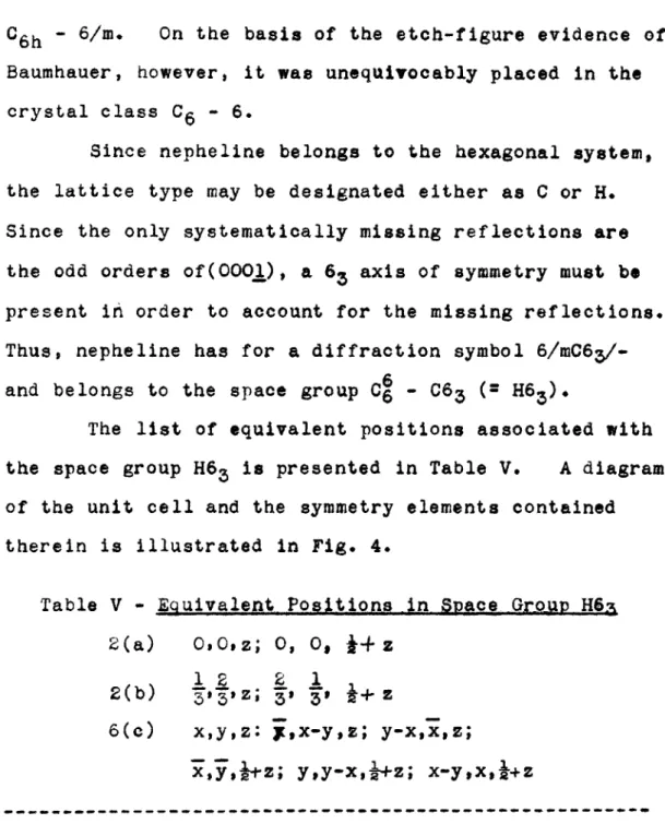
C6h - 6/m. On the basis of the etch-figure evidence of Baumhauer, however, it was unequivocably placed in the crystal class C6 - 6.
Since nepheline belongs to the hexagonal system, the lattice type may be designated either as C or H. Since the only systematically missing reflections are the odd orders of(0001), a 63 axis of symmetry must be present in order to account for the missing reflections. Thus, nepheline has for a diffraction symbol 6/mC63 /-and belongs to the space group C6 - C63 (2 H63)*
The list of equivalent positions associated with the space group H63 is presented in Table V. A diagram of the unit cell and the symmetry elements contained therein is illustrated in Fig. 4.
Table V - Equivalent Positions in Space Group H6i 2(a) 0, Oz; 0, 0, k- z
1 2 2 1
2(b) 31T, Z; ' 's, J+ z
6(c) xjyjz: isx-yo ; y-XI31z;
xsy,}tz; yy-x,-+-z; x-yxj+z
--- ----
---B. - Preliminary Considerations
Since the number of formula weights per unit cell turns out to be 8 NaAlSiO4, there are eight each of sodium,
.
o1.
Fig.4 -
Elements
in Spdce
Group
c6
C6
-C6
3
+0+0
Qi+
0 +0+.
I
(H6)
.
01+
ok. +0 0+ Oj'+' fo o+('A
In order to conform to the elements of the space group, it must be concluded that there are essentially two types each of sodium, silicon, and aluminum atoms, and six types of oxygen atoms. For example, two of the eight sodium atoms are of one type and the remaining six are of the other type. If such a distinction between the atoms is made, it is found that there is one group containing six sodium atoms, one containing six aluminum, one with six
silicon, and five groups with six oxygen atoms each. There are left then two each of sodium, aluminum, silicon, and oxygen atoms.
If one atom of each group of six is placed in a general position in the cell, the symmetry elements of the cell immediately account for the other five atoms of the group as being symmetry-equivalent atoms according to Table V. Thus, only one atom each of sodium, silicon, aluminum, and five oxygen atoms must be placed in general positions in the cell.
There still remain to be placed two atoms each of sodium, silicon, aluminum, and oxygen. Since according to Table V there are two sets of equivalent positions located on symmetry elements, namely, 2(a) - the 63 axis, and 2(b) - the 3-fold axes, these remaining atoms must be placed on symmetry elements for it is only in such posi-tions that an atom may be located without being multiplied
by the symmetry elements. The question remains as to which of the positions the sodium atoms belong and to
which ones the silicon, aluminum, and oxygen atoms belong. Since there is but one 63 axis belonging to each unit cell while there are two 3-fold axes per unit cell, and since there are two each of silicon and aluminum and oxygen atoms and only two sodium atoms in all to be
placed, it seems most reasonable that the two sodium atoms fall on the 63 axis, while one each of the silicon, aluminum, and oxygen atoms is on each of the two 3-fold axes which the space group provides. Thus, the atoms in the special positions may be readily placed as far as their positions in the XY plane are concerned.
C. - Implication Diagrams
Since a study of the Patterson plots * made from some of the very early nepheline data indicated that the Patterson plot is so complicated in the case of nepheline that analysis was impossible, no attempt was made to obtain clue as to the atomic positions from this type of diagram. The Harker synthesis2 9 in its usual form did not offer any more substantial aid.
At the time that Professor Buerger introduced the concept of the implication diagram the construction of such a plot gave the first clue as to the positions of some of the atoms. Harker syntheses were prepared in the
'4I0
implication diagrams I3(xyO) and I6(xy}) employing the Patterson-Tunell method3 1 for performing Fourier syn-theses.
Fig. 5 presents the results of the final summations given by the Patterson-Tunell method for the case of the implication diagram I3(xyO) after the data had been trans-formed from the original Harker synthesis according to the rules presented in the Buerger article. The data in this plot (and in all of the following plots) is plotted to
scale for the basic unit only, where the basic unit contains all of the necessary data, so that when it is operated on by the elements of symmetry which obtain to the plot in question, the entire contents of the unit cell result.
The implication diagram I3(xyO) (Fig. 6) showed
several sets of peaks consisting of pairs of sharply defined peaks and pairs of bluntly defined peaks. These peaks
provided several possible combinations for placing of the silicon and aluminum atoms, such as by placing a silicon atom on a sharp peak and an aluminum atom on a blunt peak, or a silicon atom on a blunt peak and an aluminum atom on a sharp peak, etc., until all of the possible permutations and combinations were tried.
The implication diagram I6(xyj) was prepared at a later time, and its importance and use will be discussed in the following section.
, '%' 15. *
a
t44~(~ ~2'0. 4)k .1 .0 AP140 b-a 300/y
= -I I I I - 'A