HAL Id: hal-01657751
https://hal.uca.fr/hal-01657751
Submitted on 2 Dec 2018
HAL is a multi-disciplinary open access
archive for the deposit and dissemination of
sci-entific research documents, whether they are
pub-lished or not. The documents may come from
teaching and research institutions in France or
abroad, or from public or private research centers.
L’archive ouverte pluridisciplinaire HAL, est
destinée au dépôt et à la diffusion de documents
scientifiques de niveau recherche, publiés ou non,
émanant des établissements d’enseignement et de
recherche français ou étrangers, des laboratoires
publics ou privés.
Multibody reconstruction of the dynamic scene
surrounding a vehicle using a wide baseline and
multifocal stereo system
Laurent Mennillo, Eric Royer, Frédéric Mondot, Johan Mousain, Michel
Dhome
To cite this version:
Laurent Mennillo, Eric Royer, Frédéric Mondot, Johan Mousain, Michel Dhome. Multibody
recon-struction of the dynamic scene surrounding a vehicle using a wide baseline and multifocal stereo
system. Workshop on Planning, Perception and Navigation for Intelligent Vehicles (satellite event of
IROS’17), Sep 2017, Vancouver, Canada. �hal-01657751�
Multibody reconstruction of the dynamic scene
surrounding a vehicle using a wide baseline and
multifocal stereo system
Laurent Mennillo
∗†, ´
Eric Royer
∗, Fr´ed´eric Mondot
†, Johann Mousain
†and Michel Dhome
∗∗Pascal Institute, Clermont Auvergne University, UMR 6602 - UCA / CNRS / SIGMA
63178 Aubi`ere, France
†Technocentre RENAULT
78280 Guyancourt, France
Abstract—Multibody Visual SLAM has become increasingly popular in the field of Computer Vision during the past decades. Its implementation in robotic systems can benefit numerous appli-cations, ranging from personal assistants to military surveillance to autonomous vehicles. While several practical methods use multibody enhanced SfM techniques and monocular vision to achieve scene flow reconstruction, most rely on short baseline stereo systems. In this article, we explore the alternative case of wide baseline and multi-focal stereo vision to perform incremen-tal multibody reconstruction, taking inspiration from the increas-ingly popular implementation of heterogeneous camera systems in current vehicles, such as frontal and surround cameras. A new dataset acquired from such heterogeneous camera setup mounted on an experimental vehicle is introduced in this article, along with a purely geometrical method performing incremental multibody reconstruction.
I. INTRODUCTION
This article is related to the automotive industry and focuses on driving aid systems and autonomous navigation. Multibody SLAM techniques often rely on expensive and difficult-to-integrate sensors, such as lidar systems [23]. By contrast, dig-ital video cameras have been extensively developed during the last decades, rapidly becoming small, efficient and inexpensive products. Most of the vehicles currently available dedicate these sensors to provide the driver a convenient visualization of the vehicle surroundings. Recently, more specific tasks involving video cameras (road sign and pedestrian detection, automatic emergency braking, line departure warning, blind spot monitoring, etc.) have been introduced. Besides, precisely calibrated cameras allow for the tridimensional reconstruction of an observed scene, which extends the potential applica-tions of these systems. Some are straightforward, like visual odometry or visual simultaneous localization and mapping, but it is also possible to dynamically evaluate the road context related to this information to further enable the autonomous capabilities of a vehicle, which have been explored in appli-cations such as scene understanding, obstacle avoidance or path planning [2], [4]. Moreover, behavior modeling of mobile objects could further improve the detection of dangerous situations (pedestrian crossing, brutal stop of another vehicle, excessive speed, bad road positioning, right of way violation,
etc.). While several practical methods use multibody enhanced SfM techniques and monocular vision to achieve scene flow reconstruction, most rely on short baseline stereo systems. In this article, we explore the alternative case of wide baseline and multifocal stereo vision to perform incremental multi-body reconstruction, taking inspiration from the increasingly popular implementation of heterogeneous camera systems in current vehicles, such as frontal and surround cameras.
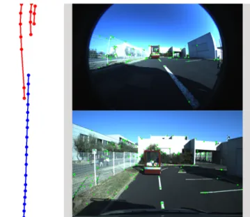
Figure 1. Example of trajectories reconstruction. In this sequence, the acquisition vehicle is following another moving vehicle. The blue trajectory is from the acquisition vehicle, while the red trajectories correspond to the red points on the moving vehicle visible in the two views on the right.
II. RELATEDWORK
Intelligent vehicles today can be considered as the practice field of many computer vision algorithms. Indeed, research on the subject has led to several applications such as visual odom-etry [16] or visual simultaneous localization and mapping [3]. However, most methods focus on the reconstruction of static, rigid environments. Dynamic parts of the scene are often considered as outliers and filtered out using robust statistical
methods like RANSAC. Such approach could seem inappro-priate in the context of driving aid systems and autonomous vehicles, as most hazardous traffic situations involve mobile objects, but one can then consider that the high complexity and computational cost of such dynamic reconstruction algorithms have been the limiting factors of their practical expansion.
Multibody VSLAM refers to the ensemble of techniques used to reconstruct and track the static and mobile objects of a dynamic scene in three dimensions with vision. However, while some techniques rely on global data optimization, this article focuses on incremental reconstruction, which allows its online use in actual moving vehicles. These incremental techniques can further be divided into two categories, mainly depending on the number of cameras used for reconstruction. Monocular methods are the most challenging ones, in that they have to compensate the camera ego-motion parameters to retrieve the independent motion of each mobile object of the scene. Many incremental monocular methods [17], [8], [19] extend classical Structure-from-Motion theory [7] to the challenging case of dynamic scenes involving multiple rigid-body motions. The different elements to consider for such frameworks involve features matching and clustering based on their estimated motion, also known as subspace clustering [22], the tracking and independent reconstruction of these feature clusters with respect to their relative camera pose and finally the aggregation of all the reconstructed elements to scale.
The second category of methods used to perform multibody VSLAM involve multiple camera systems, generally under the form of identical stereo camera pairs which allow for dense reconstruction and segmentation of mobile objects using depth maps from optical flows [13], [18], [1], [24]. While short baseline stereo has been well studied in the context of autonomous navigation, it is not the case of multifocal and wide baseline stereo cameras pairs. The method presented in this article is intended to address this case on a heterogeneous multi-camera system.
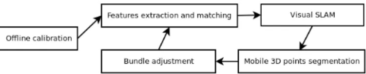
Figure 2. Overview of the framework used in our method.
III. FRAMEWORK
An overview of the framework presented in this article is shown in figure 2. After an initial offline step of intrinsic and extrinsic camera calibration following the method intro-duced in [9], feature points are then extracted, matched and undistorted for each frame using the unified camera model presented in [5] and then fed to the visual SLAM module, which estimates the ego-motion parameters of the multi-camera system. These parameters are then used to compute the multi-view geometric constraints of the segmentation process
which filters and reconstructs the static and mobile features. Following the SLAM and segmentation procedures, the recon-structed points and camera poses are further refined by two dedicated optimization steps minimizing the reprojection error with bundle adjustment.
A. Sparse feature extraction and matching
Dense feature matching from stereo camera pairs has been well studied for the case of dynamic scene reconstruction. These techniques often involve the use of dense flow fields to detect and segment the rigid-body motions of the scene [13]. By contrast, while obtaining disparity maps from wide baseline systems has proven achievable [21], the current methods are not appropriate for time-constrained scenarios. The approach used in this article, while conventional, produces accurate extraction and matching of sparse features in the case of wide baseline and multifocal stereo.
To account for the heterogeneous focal lengths of our system, the frames obtained from cameras with longer focal lenses are downsampled and slightly blurred to adjust for the different size (pixelwise) of the elements in the scene that are simultaneously seen by cameras with shorter focal lenses. These downsampled frames are then used for feature extraction.
The SIFT feature detector and descriptor [11] has been chosen for feature detection and description as it produces a large number of relatively stable points.
The feature extraction process is divided into three parts for each frame. SIFT feature detection is first performed on the entire frame to get an initial feature set. The frame is then divided into blocks of an n by n grid, while the features belonging to each block are grouped into clusters. The best features are finally retained for each cluster. This first part allows for a good feature repartition on the frame. The second part is designed to enhance the temporal detection of previ-ously triangulated features. We used the Lucas Kanade method as introduced in [12] to track these features on consecutive frames and thus increase the chances to detect the same 3D point for a longer period of time. The last part finally merges the two sets of features, eliminating duplicates based on their respective euclidean distance. The result of this extraction process is a feature set fi,t for each frame, where i ∈ 0 . . . m
and t ∈ 0 . . . n correspond respectively to the camera and time of observation.
The feature matching process between two sets fi,tand fi0,t0
then rely on two geometric constraints. A locality constraint Lcand the epipoplar constraint Ec.
The locality constraint Lc is used for the temporal matching of features seen in frames acquired with the same camera at different times. This constraint allow for a feature x ∈ fi,t
to be matched with a feature x0 ∈ fi,t0 if the euclidean
distance dE between x and x0 is inferior to a threshold dLc.
Each potential match p(x, x0) must then satisfy the following equation
The epipolar constraint Ec is used for the stereo matching of features seen in frames acquired simultaneously by different cameras with overlapping fields of view and whose extrinsic parameters are known beforehand. This constraint allow for a feature x ∈ fi,t to be matched with a feature x0 ∈ fi0,t if
the euclidean distance to their respective epipolar lines l0 and l is inferior to a threshold dEc. Each potential match p(x, x0)
must then satisfy the following equation
p(x, x0) ⇐⇒ (
dE(x, l0) < dEc
dE(x0, l) < dEc
where l = Fi,iT0x0, l0 = Fi,i0x and Fi,i0 is the fundamental
matrix between cameras i and i0.
Following these two constraints, when more than one poten-tial match p(x, x0) exists for either feature in their respective sets, the best match m(x, x0) retained is the one for which the euclidean distance dE, or L2, between each feature descriptor
(not the distance in pixels) is minimal min(dE(x, x0)).
Finally, the multi-camera matching scheme allows each camera to be stereo matched with the other ones for which there is an overlapping field of view and temporally matched at consecutive times of observation. That last point is of crucial importance for the tracking of features, meaning that a feature must at least be matched once temporally at the current time of observation to be tracked in subsequent frames.
Figure 3. Reconstruction of the rigid environment generated by the visual SLAM module and its corresponding trajectory.
B. Visual SLAM
The visual SLAM module is independent of the following segmentation process proposed in this article. Its main pur-pose is to estimate the ego-motion parameters of the multi-camera system in order to efficiently compute the geometric constraints used in the segmentation process. The approach chosen is a bundle adjustment visual SLAM, as presented in [14], in opposition to filter based approaches such as [3] for its higher accuracy [20]. Briefly, the initial epipolar geometry is computed by the 5-point algorithm [15] with RANSAC for the first three frames and the subsequent poses are determined by camera resection [6], [10]. During this incremental process, the 3D points are reconstructed with the mid-point algorithm
and some sets of frames, referred as key frames, are selected for local optimization by bundle adjustment to further refine their respective camera poses and associated 3D points. A full sequence reconstruction and its associated trajectory, generated by the visual SLAM module, are shown in figure 3.
C. Mobile 3D points segmentation and tracking
A 3D point X must at least be associated with a couple of observations (oXi,t, oXi0,t0), each from a specific camera i, i0 ∈
0 . . . m at a specific time t, t0 ∈ 0 . . . n, for its reconstruction. These observations can either be temporal (i = i0 ∧ t 6= t0)
or stereo (i 6= i0∧ t = t0) and correspond to feature matches
m(x, x0) obtained from the feature matching module. A 3D point can also be associated with more than two observations, all of which form the set oX of the observations associated
with the 3D point X. One should note that at this point, all observations are retained from the feature matching module to allow for mobile object detection, contrary to most SLAM methods which eliminate the outliers that do not satisfy the main epipolar geometry of the scene. The objective of the mobile segmentation module is then to determine from these observations the class of their associated 3D point, which can either be static (X ∈ S), mobile (X ∈ M ) or into the outlier class (X ∈ O).
1) 3D point consistency: A 3D point is considered as consistentwhen it satisfies the consistency constraint Cc. This constraint specifies that the reprojection error of this point for all its observations is inferior to a certain threshold tCc, which
translates as
Cc(oX) ⇐⇒ ∀oXi,t ∈ oX, (oX
i,t− Pi,tX) < tCc
where Pi,tis the projection matrix of the ithcamera at time
t. Incidentally, a static 3D point (X ∈ S) must be consistent for all of its associated observations.
2) 3D point mobility: On the opposite, a mobile 3D point might not be consistent for all its temporal observations. However, each 3D point can be split temporally and must remain consistent for each of its temporalities, which allow for different positions of the point at different times. Then, the first mobility constraint M c1 specifies that
M c1(oX) ⇐⇒ ∀t, ∀oXi,t∈ oXt , (oXi,t− Pi,tX) < tM c1
where oXt is the set of observations associated to the point
X at time t. Considering that the point X is moving, only stereoobservations allow for its reconstruction at time t. There must then be at least two stereo observations (oXi,t, oXi0,t) for
each temporality t. This leads to the second mobility constraint M c2, which states that
M c2(oX) ⇐⇒ ∀t, |oXt | ≥ 2
Finally, the detection of a mobile point being only possible from several temporal observations, there must at least be two
temporal observations (oX
i,t, oXi,t0) in the set oX. Hence the third
mobility constraint which states that
M c3(oX) ⇐⇒ ∃(oXi,t, oXi,t0) ∈ (oX)2, t 6= t0
In practice, while the minimum of temporal observations is two, a minimum of three has been used to mitigate false positives by ensuring that the trajectory of these observations is consistent (see III-C5), meaning that a mobile 3D point has to be tracked in at least three consecutive frames.
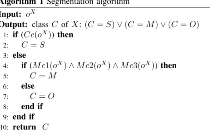
3) Segmentation algorithm: Using the consistency and mo-bility constraints, the segmentation process then proceeds with the following algorithm for each 3D point X to determine its class C (static, mobile or outlier).
Algorithm 1 Segmentation algorithm Input: oX
Output: class C of X: (C = S) ∨ (C = M ) ∨ (C = O)
1: if (Cc(oX)) then
2: C = S
3: else
4: if (M c1(oX) ∧ M c2(oX) ∧ M c3(oX)) then
5: C = M 6: else 7: C = O 8: end if 9: end if 10: return C
Each 3D point is first checked for consistency and consid-ered as static if consistent. If not, the point is further tested for mobility, in which case it is considered as mobile if all mobility constraints are satisfied and as an outlier if not. The outliers are then discarded at this point.
4) 3D point splitting for optimization: Following the seg-mentation algorithm, each mobile point is then split temporally as a set of individual points Xt which correspond to the
different positions of the point X at each temporality t. This step allows for a generic optimization of all 3D points regardless of their class (C = S or C = M ), which is performed on all mobile 3D points Xt by minimizing their
reprojection error for all their observations oXt with bundle
adjustment.
5) Trajectory consistency: As a final step and to further refine the segmentation, the trajectory of each mobile point X composed of the individual points Xt is checked for
its consistency. Several constraints of smoothness for speed and changes in direction are used. The constraint for speed specifies that the euclidean distance allowed between each pair of consecutive points (Xt, Xt0) is comprised between
dmin< dE(Xt, Xt0) < dmax. Similarly, as each mobile object
is assumed to rest on the ground plane, the change in elevation allowed between each pair of consecutive points (Xt, Xt0)
must not exceed a threshold dElevation. As for the changes
of direction, the angle formed by each triplet of consecutive
points (Xt, Xt0, Xt00) projected on the ground plane must not
exceed a threshold α. All these constraints on the trajectory of each mobile point X allow for the detection and dismissal of erratic movements generated by false matches occurring in the feature matching module.
D. Parameter tuning
Each step of the described framework rely on various parameters affecting the overall performance of the proposed method. While some of the values used for these parameters directly come from the literature, an empirical tuning aproach has been adopted to retain the best value for the other parameters in regard to the results obtained on our associated dataset. More precisely, parameters in section III-C, which is the main contribution of our method, use the following values for the consistency and first mobility constraints tCc = 3.0,
tM c1 = 3.0, while the values used to ensure the trajectory
consistency in section III-C5 are dmin = 0.1, dmax = 10.0,
dElevation= 1.0 and α = 60.0. One should although consider
that these values are specifically intended to work well on our associated dataset and are thus given on an indicative basis only.
v
Figure 4. Top-down view of the vehicle with the four cameras and overlapping fields of view. According to our feature matching scheme, temporal matching is performed for each camera, while stereo matching is performed between the windscreen camera (in blue) and the three others (in orange and red) and between the front grille camera (in orange) and the side cameras (in red).
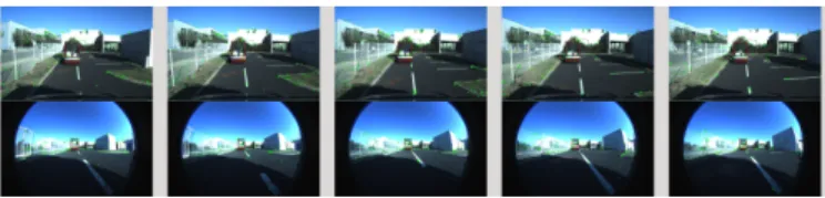
Figure 5. Views acquired with the four cameras. Top left is the front grille camera, top right the windscreen camera and bottom left and right are the side-left and side-right cameras.
IV. DATASET
While several datasets allowing for the evaluation of scene flow have recently been introduced, notably the KITTI dataset for scene flow estimation [13], no publicly available dataset to our knowledge uses an array of wide baseline and multifocal stereo cameras, which is the reason behind the creation of our own. The dataset presented in this article has been acquired in a realistic but controlled environment, which is composed of static and mobile elements such as cars and pedestrians. A total of eight different sequences corresponding to different road traffic scenarios at low speed have been acquired in order to assess the robustness of the proposed algorithm and the quality of the reconstructions.
The experimental vehicle has been equipped with four rigidly mounted digital cameras and a D-GPS. Spec-wise, the cameras use identical 2.3 MP, global shutter and syn-chronized sensors which record at 25 frames per second. The synchronization part of the acquisition process, being of utmost importance to ensure the geometrical correctness of our method, has been performed by hardware triggering. Three cameras are equipped with fisheye lenses equivalent to a 185 degrees horizontal FOV, while the fourth is equipped with a longer focal lens equivalent to an 80 degrees horizontal FOV. The fisheye cameras have been respectively placed on the front grille, pointing front in the longitudinal axle of the vehicle and on each side of the roof above the driver and passenger doors, pointing to the left and right perpendicular to the front camera. Finally, the last camera has been placed on the roof, above the windscreen, pointing front in the longitudinal axle of the vehicle. A top-down view of the vehicle with the four cameras and overlapping fields of view is shown in figure 4, while actual views acquired with the four cameras are shown in figure 5.
The choices of position, specs and optical characteristics of the cameras have been motivated by the increasingly popular implementation of heterogeneous camera systems in current vehicles, such as frontal (e.g., Mobileye cameras) and sur-round cameras (e.g., Asur-round View Monitoring systems). These
experimental conditions should then help demonstrate the potential uses of such multi-camera systems in the challenging task of autonomous navigation.
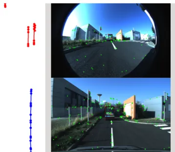
Figure 6. Example of false positive. The red trajectory in the top left corner is due to false matches misinterpretation on the traffic light.
V. EXPERIMENTAL RESULTS
Qualitative results have been obtained from the algorithm on various sequences from our dataset. One example of trajectory reconstruction is shown in figure 1. In this particular case, the acquisition vehicle whose trajectory is shown in blue is following another moving vehicle in front. Three mobile points are tracked and reconstructed simultaneously on the moving vehicle, which corresponds to the three red trajectories on the top left of the figure. These red points are also visible on the moving vehicle in the two provided views. One can note that some of the green points, which are static 3D points, also lie on the moving vehicle. These green points are not considered as mobile as they have not been tracked and stereo matched for three consecutive frames. While this also explains the relatively few number of mobile points detected, this is a limitation of the current state of the method, as the segmentation constraints used do not allow for a false observation to be associated with a moving 3D point, in which case the point becomes an outlier and is then dismissed. Views of the windscreen and front grille cameras corresponding to this particular trajectory can be seen in figure 7.
While several similar valid occurrences of tracking and reconstruction appear in the different sequences, some false positives are also to be noted. In figure 6, one can see the false red trajectory in the top left corner. This false positive is caused by false matches of features on the traffic light visible on the left in the views. These matches are correct according to the epipolar matching constraint Ec, as they lie on the epipolar lines, but are not pointing at the same static 3D point (one is at the top, the other at the bottom of the light) on the object and are thus misinterpreted as a moving point. These false
positives occur more frequently in repeating patterns areas such as the ground, grass, or the grilling visible on the left of the views in figure 6. Finally, although being semantic errors rather than geometric ones, shadows of moving objects can also be misinterpreted as moving areas and thus be considered as false positives.
Figure 7. Views of the windscreen and front grille cameras corresponding to the trajectories shown in figure 1.
VI. CONCLUSION AND FUTURE WORKS
The observed qualitative results show that the purely ge-ometrical method presented in this article works as intended on our dataset. However, several improvements can be made regarding the results. The reconstructed moving trajectories can indeed be considered as the starting point of a denser matching surrounding the area near the moving features. This could, in turn, allow to work with more points per moving object, which would enable their tracking and reconstruction to scale in the non-overlapped field of views of the multi-camera system. Also, some flexibility during the segmentation process, allowing to work on a larger number of points, could be achieved by pondering each observation and scoring the motion potential of each point instead of considering it as an outlier. These perspectives will eventually be explored in future works.
REFERENCES
[1] M. Bleyer, C. Rhemann, and C. Rother. Extracting 3d scene-consistent object proposals and depth from stereo images. pages 467–481. Springer, 2012.
[2] M. Buehler, K. Iagnemma, and S. Singh. The DARPA urban challenge: autonomous vehicles in city traffic, volume 56. Springer, 2009. [3] A. J. Davison, I. D. Reid, N. D. Molton, and O. Stasse. MonoSLAM:
Real-time single camera SLAM. Pattern Analysis and Machine Intelli-gence, 29(6):1052–1067, 2007.
[4] A. Geiger, M. Lauer, C. Wojek, C. Stiller, and R. Urtasun. 3d traffic scene understanding from movable platforms. Pattern Analysis and Machine Intelligence, 36(5):1012–1025, 2014.
[5] C. Geyer and K. Daniilidis. A unifying theory for central panoramic sys-tems and practical implications. In European Conference on Computer Vision, pages 445–461. Springer, 2000.
[6] B. M. Haralick, C.-N. Lee, K. Ottenberg, and M. N¨olle. Review and analysis of solutions of the three point perspective pose estimation problem. International Journal of Computer Vision, 13(3):331–356, 1994.
[7] R. Hartley and A. Zisserman. Multiple view geometry in computer vision, Second Edition. Cambridge Univ. Press, 2003.
[8] A. Kundu, K. M. Krishna, and C. Jawahar. Realtime multibody visual slam with a smoothly moving monocular camera. In International Conference on Computer Vision, pages 2080–2087. IEEE, 2011. [9] P. L´ebraly, E. Royer, O. Ait-Aider, C. Deymier, and M. Dhome. Fast
calibration of embedded non-overlapping cameras. In International Conference on Robotics and Automation, pages 221–227. IEEE, 2011. [10] V. Lepetit, F. Moreno-Noguer, and P. Fua. Epnp: An accurate o (n) solution to the pnp problem. International Journal of Computer Vision, 81(2):155–166, 2009.
[11] D. G. Lowe. Distinctive image features from scale-invariant keypoints. International Journal of Computer Vision, 60(2):91–110, 2004. [12] B. D. Lucas and T. Kanade. An iterative image registration technique
with an application to stereo vision. In Proceedings of the 7th International Joint Conference on Artificial Intelligence - Volume 2, IJCAI’81, pages 674–679, San Francisco, CA, USA, 1981. Morgan Kaufmann Publishers Inc.
[13] M. Menze and A. Geiger. Object scene flow for autonomous vehicles. In Computer Vision and Pattern Recognition, pages 3061–3070. IEEE, 2015.
[14] E. Mouragnon, M. Lhuillier, M. Dhome, F. Dekeyser, and P. Sayd. Real time localization and 3d reconstruction. In Computer Vision and Pattern Recognition, volume 1, pages 363–370. IEEE, 2006.
[15] D. Nist´er. An efficient solution to the five-point relative pose problem. Pattern Analysis and Machine Intelligence, 26(6):756–770, 2004. [16] D. Nist´er, O. Naroditsky, and J. Bergen. Visual odometry. In Computer
Vision and Pattern Recognition, pages I–652. IEEE, 2004.
[17] K. E. Ozden, K. Schindler, and L. Van Gool. Multibody structure-from-motion in practice. Pattern Analysis and Machine Intelligence, 32(6):1134–1141, 2010.
[18] N. D. Reddy, I. Abbasnejad, S. Reddy, A. K. Mondal, and V. Devalla. Incremental real-time multibody vslam with trajectory optimization using stereo camera. In Intelligent Robots and Systems, pages 4505– 4510. IEEE, 2016.
[19] R. Sabzevari and D. Scaramuzza. Monocular simultaneous multi-body motion segmentation and reconstruction from perspective views. In International Conference on Robotics and Automation, pages 23–30. IEEE, 2014.
[20] H. Strasdat, J. Montiel, and A. J. Davison. Real-time monocular slam: Why filter? In International Conference on Robotics and Automation, pages 2657–2664. IEEE, 2010.
[21] E. Tola, V. Lepetit, and P. Fua. Daisy: An efficient dense descriptor applied to wide-baseline stereo. Pattern Analysis and Machine Intelli-gence, 32(5):815–830, 2010.
[22] R. Vidal. Subspace clustering. Signal Processing Magazine, 28(2):52– 68, 2011.
[23] C.-C. Wang, C. Thorpe, S. Thrun, M. Hebert, and H. Durrant-Whyte. Simultaneous localization, mapping and moving object tracking. The International Journal of Robotics Research, 26(9):889–916, 2007. [24] K. Yamaguchi, D. A. McAllester, and R. Urtasun. Efficient joint
seg-mentation, occlusion labeling, stereo and flow estimation. In European Conference on Computer Vision, pages 756–771. Springer, 2014.