Application of cross-hole seismic tomography in characterization of heterogeneous aquifers.
Texte intégral
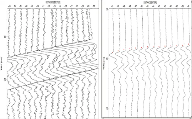
Figure
Documents relatifs
To overcome this difficulty, we propose a formalism based on linear combinations of model parameters (macro-parameters) that allows to compute uncertainties on relevant
A classical approach to quantify uncertainties consists of the analysis of the Hessian matrix (or its inverse: the a posteriori covariance matrix) associated with the linearized
Using the P and S travel time data and a Vp/Vs ratio of 1.68 derived for the same area [Saccorotti et al., 2004; Escuer , 2006], the method provides relocated hypocenters and a
A comparison between them is made and correlation analysis demonstrates that the generated earthquake signals have the same behavior as the natural ones, and have approximately
Nous détaillons su essivement la otation de l'extra tion d'informations, puis elle de leur fu-.. sion, en examinant pour ha une la transposition des dimensions qui la
Dans cette étude, nous nous intéressons à valoriser les sédiments de dragage et particulièrement le sédiment de la Rance comme un matériau minéral en substitution partielle du
J’ai marché hier Comme aujourd’hui J’ai chanté toute la nuit Mais à quand sera la fin?. J’ai vu dans ce monde toutes folies
Malgré des postes en apparence plutôt routiniers et une pénibilité physique moindre que les autres utilisa- teurs d’outils numériques, les utilisateurs d’outils
