HAL Id: in2p3-00113802
http://hal.in2p3.fr/in2p3-00113802
Submitted on 14 Nov 2006
HAL is a multi-disciplinary open access
archive for the deposit and dissemination of
sci-entific research documents, whether they are
pub-lished or not. The documents may come from
teaching and research institutions in France or
abroad, or from public or private research centers.
L’archive ouverte pluridisciplinaire HAL, est
destinée au dépôt et à la diffusion de documents
scientifiques de niveau recherche, publiés ou non,
émanant des établissements d’enseignement et de
recherche français ou étrangers, des laboratoires
publics ou privés.
SAM: A new GHz sampling ASIC for the H.E.S.S.-II
front-end electronics
E. Delagnes, Y. Degerli, P. Goret, P. Nayman, F. Toussenel, P. Vincent
To cite this version:
E. Delagnes, Y. Degerli, P. Goret, P. Nayman, F. Toussenel, et al.. SAM: A new GHz sampling
ASIC for the H.E.S.S.-II front-end electronics. 4th International Conference on New Developments in
Photodetection, Jun 2005, Beaune, France. pp.21-26, �10.1016/j.nima.2006.05.052�. �in2p3-00113802�
SAM: a new GHz sampling ASIC for the
H.E.S.S.-II Front-End Electronics.
E. Delagnesa*, Y. Degerlia, P. Goreta, P. Naymanb, F. Toussenelb, P. Vincentb.
a CEA, DSM/DAPNIA, CE-Saclay, F-91191 Gif-sur-Yvette Cedex, France. b LPNHE, IN2P3/CNRS Universités Paris VI & VII, Paris, France
* Corresponding author: [email protected], phone: 33 (1) 69 08 22 52, fax: 33 (1) 69 08 31 47
Abstract
The H.E.S.S.-II front-end electronics, with its 20 GeV energy threshold, will require a much higher acquisition rate capability and a larger dynamic range than was relevant for H.E.S.S.-1. These constraints led to the development of a new ASIC, called SAM for Swift Analogue Memory, to replace the ARS used for H.E.S.S.-1. The SAM chip features 2 channels for the low and high gain outputs of a PMT, each channel having a depth of 256 analogue memory cells. The sampling frequency is
adjustable from 0.7GS/s up to 2GS/s and the read-out time for one event is decreased from 275 µs down to 2.3 µs. The SAM input bandwidth and dynamic range are increased up to 300 MHz and more than 11 bits respectively.
Keywords: ASIC, Analogue memory, Sampler, Analogue to digital conversion , Readout.
I. Introduction
The H.E.S.S. [1] experiment is a new generation of ground based atmospheric Cherenkov detector located in Namibia and dedicated to gamma ray astronomy in the 100GeV-10TeV energy range. In its phase I (H.E.S.S.-I), it consists of an array of four 107 m2 telescopes working in stereoscopic mode. For each telescope, the compactness of the camera, located at the focal plane, accommodates all the data acquisition electronics. The camera consists of 960 closely packed photomultiplier tubes (PMT). Its electronic read-out architecture is based on the ARS0 chip [4] that allows digitising the PMT signals at a GHz rate for moderate power consumption. The A-D conversion of the PMT signals is achieved inside the camera, so that very few cables come out from the camera. The first telescope has been taking data reliably since June 2002 and the full four telescope set-up is fully operational since the end of 2003. In the second phase of the experiment (H.E.S.S.-II) [2], it is planned to add a 600 m2 telescope in the centre of the existing array, equipped with a 2048 P.M.T.s camera.
In stand alone mode, its energy threshold will be between 10 to 20 GeV, connecting the energy range of H.E.S.S. to those of satellite experiments and giving access to new objects such as pulsars and AGNs at larger read-shift.
Above 50 GeV, the observations with the five telescopes array in coincidence will result in significantly improved sensitivity, angular and energy resolutions. The front-end electronics architecture of this new instrument will be very similar to the one of the first telescopes. But, as the ARS0 chip cannot fulfil new requirements arising from the lowering of the energy threshold, a new sampling chip SAM (Swift Analogue Memory ) has been designed. This paper first discusses the specifications for this new chip, describes its architecture and presents measurement results on the first SAM prototype.
2. The H.E.S.S.-I front-end electronics and its limitations
The signal from each of the 960 PMTs of each of the four H.E.S.S.-I cameras is amplified and digitised in a (8-channels) front end electronics board [3].
The most stringent specifications for these boards are: - cover a range from 1 to 2,000 photoelectrons
- deal with the very high rate of noise due to the Night Sky Background (N.S.B.) which can reach 1.108 photoelectron/s for each pixel.
Note that the latter constraint requires that the camera readout gate has to be set as short as possible. A level 1 trigger, used to cut background events down to a negligible level, is built by a multiplicity trigger for each camera (the camera trigger) combined with a fast coincidence between telescopes in the stereoscopic mode.
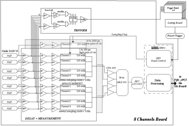
As shown on Fig 1, at the input of the front-end board, the signal coming from the PMT is split three ways to feed:
- a sub-nanosecond discriminator, with a threshold set to ~3 photoelectrons, used to build the level 1 trigger.
-two acquisition channels with high and low gains in the ratio of 12.5 to cover the required dynamic range.
After amplification, the PMT signal is sent to an ARS0 chip, a 4 channels analogue memory used as a circular buffer, which was originally developed for the ANTARES experiment [4]. Each input signal is continuously sampled at a rate of 1GSample/s and stored in the successive cells of a bank of 128 capacitors. After writing in the last cell, the circuit overwrites the first cell, then the second and so on. Whenever a final camera trigger occurs, the analogue memory is frozen. When the latter is detected, then a given number of cells Nf can be read back, starting from a cell located at a programmable offset Nd from the cell corresponding to the arrival time of the camera trigger.
Nd and Nf are tuned in such a way that only the cells containing the signal associated with the trigger are read. As the memory depth is 128, this system enables the readout of signals recorded up to 128ns before the trigger arrival time. This is enough to deal with the local trigger latency of 70ns. Nf is set to 16ns to match the duration of the air shower Cherenkov light, spread by the Davis-Cotton mirror, and after integration of the pulses by the bandwidth limited input buffers of the ARS0 (80Mhz). Following readout, the analogue samples from the 16 channels of the 4 ARS of a board are multiplexed and digitised by a 12-bit, 3MSample/s ADC. The ADC output is written into a FPGA which can be configured either to calculate the sum of the 16 samples or, for debugging purpose, to sent all the samples to the DAQ system. Because of a non negligible crosstalk between the ARS0 channels, a chip is used to treat only high gain or low gain data.
This system has proven its excellent performances and high reliability during the three years of operation of the H.E.S.S.-I phase. However, as detailed below, some limitations prevent using the ARS0 for the next phase H.E.S.S.-II.
First, the ARS-ADC section is the major bottleneck in the acquisition data flow. The digitisation of a 16 cells Cherenkov event takes 275 µs leading to a ~10% dead-time when the experiment operates at its nominal acquisition rate of 300Hz.
Then, as explained previously, the ARS0 limited analogue input bandwidth of 80MHz broadens the 5ns-long PMT signal by more than a factor of two, forcing to use a quite long integration window resulting in a larger noise from the night sky background.
3. From H.E.S.S.-I to H.E.S.S.-II, description of the SAM chip
Considering the excellent results of the I DAQ and the very tight schedule to build H.E.S.S.-II, the design of the Front End electronics for the new telescope is very similar to that of the existing telescopes. In particular, it is based on the same dual-gain architecture using fast analogue circular memories . However, because of the lower energy threshold: i) the expected trigger rate for each pixel of the H.E.S.S.-II camera is expected to be at least an order of magnitude higher than in H.E.S.S.-I , ii) the dynamic range of H.E.S.S.-II will extend up to 5000e- and iii) a fifo buffer is added in order to manage a second level trigger and to smooth the trigger fluctuations as shown on Fig 2. Since these new requirements cannot be fulfilled by the ARS0, a new analogue memory, named SAM (Swift Analogue Memory), had to be designed.
Its functionality is exactly the same as that of the ARS0, as described in paragraph 2. The main requirements for the new SAM chip, compared to the ARS0, are:
- a fast readout compatible with event rates up to 100kHz. - a dynamic range in the 11-12 bits range
- an increased input bandwidth of 300MHz - a crosstalk reduced to few per mil
- a linearity better than 2% over the full dynamic range
- a standard sampling frequency up to 2 GS/s with a nominal value of 1GS/s - a memory depth increased to 256 cells (to cover a 128ns time window at 2GS/s) - a power consumption of ~300mW/ chip.
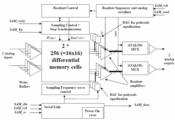
The SAM chip, which bloc diagram is shown in Fig 3, uses the 3.3V CMOS AMS 0.35µm technology. Its area is 10mm2 and it is mounted in a compact QFP100, 0.5mm pitch, package.
It features only two channels used to sample the high or low gain signals of a PMT.
As in the ARS, the high sampling frequency (Fs) of the SAM is obtained by a virtual multiplication of the lower frequency clock (Fp) using internally servo-controlled Delay Line Loops (D.L.L.).
But, as shown in Fig 4, each analogue memory channel is configured as a matrix of 16 lines with 16 capacitors each, similar to the one described in details in [5].The write pointer manager and the D.L.L. system have been designed so that :
- successive capacitors in the same column contain samples taken at 1/Fs intervals - successive capacitors in the same line contain samples taken at 1/Fp=16/Fs intervals. Each line of the matrix is buffered and read by dedicated amplifiers. This architecture has been preferred to the standard linear array of capacitors, as used in ARS0, because of its larger bandwidth to power-consumption ratio and higher switching noise immunity.
This particular structure enables a fast parallel analogue readout of groups of 16 consecutive cells, spread over one or two columns. The data from each channel are then multiplexed and digitised by external ADC at a rate of 11 MHz.
A special design effort has been made to avoid DLL unlock during readout which would introduce extra dead time between events.
Due to the matrix structure, each line has its own offset, causing a cell to cell pedestal dispersion. In order to cancel this effect, the chip provides two 7-bit programmable DACs for each line which should be set during a calibration phase previous to the acquisition.
The use of the matrix structure, rather than the linear one, results on a more complex digital section, especially concerning the system calculating the position of the read-pointer at the trigger arrival and the one controlling the output multiplexing.
As the SAM requires only two control signals, and the associated clocks, for the write and read operations, its interfacing with the FPGA controller is very simple.
The DACs and the Nf values are programmable through a serial link which is also used to configure the chip in various special operating modes, or to access built-in test functions.
To reduce digital crosstalk, the 2 analogue channels of the chip are fully differential and all the SAM digital inputs and outputs are using LVDS standard. For a better control of the coupling through parasitic elements, and because the digital and analogue functions are greatly interleaved, the layout is a full custom design.
4. Performances of the SAM chip
The SAM test board had been designed as a prototype of the H.E.S.S.-II front-end electronics. It includes two dual-gain (x1 and x25) channels, each fitted with a fast discriminator to allow auto-triggering. In this set-up, the conditions for noise measurements are not optimised but are representative of the final environment.
All the measured characteristics of this prototype, summarized in table I, actually match our expectations.
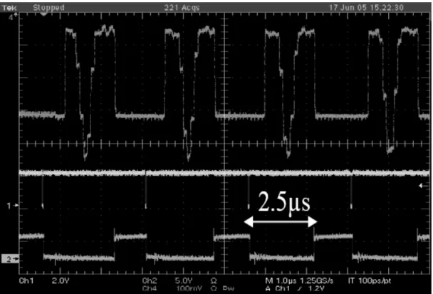
Fig 5 illustrates the capability of the SAM to operate at acquisition rates as high as 400 kHz without visible signal distortion. Both the fast readout operation (16 samples read in 1.6µs) and the stable DLL servo control design are validated.
The chip characterization has been performed using the nominal 1GS/s sampling rate but the chip can operate up to more than 2.5 GS/s.
The chip analogue bandwidth is >250 MHz, so that a 4.5ns input pulse is widened by only 1.5 ns and a 6.5ns PM pulse is widened only to 7 ns as shown on Fig 6. This permits to shorten the integration window down to 7ns.
Before any offset correction, the chip fixed pattern noise (cell-to-cell pedestal spread) amounts to ~2.5mV rms. The automatic offset compensation procedure using the DACs, as described in paragraph 4, allows to reduce this spread down to 0.4 mV rms. This adjustment remains stable over at least two months without reprogramming the DACs. The ~0.75mV individual cell noise dominates the overall measured noise of 0.8mV rms. As useful signal range is 2V, the SAM dynamic range is 11.3 bits. In fact, the operational range is limited by distortions due to the chip input buffer slew rate for fast signals. For slower signals, this range extends up to 3V.
The crosstalk between the two channels of a chip is less than 0.3%. As for the ARS, its shape is derivative, and its integral is not measurable (<0.1%).
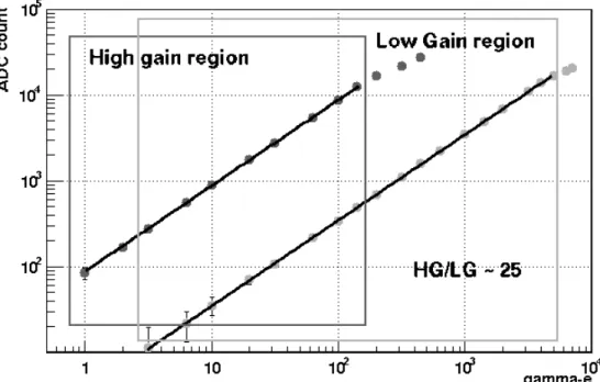
The system linearity has been evaluated using generator PM-like pulses covering the whole H.E.S.S.-II dynamic range. In these measurements, an integration window of 12 cells (12ns) was used and the results are shown in Fig 7. The corresponding non-linearity is better than 2% over the 1-5000pE range. Fig 8 shows an example of a single photoelectron spectrum measured with the SAM connected to a H.E.S.S.-I photomultiplier used in nominal conditions. An integration window of 16 ns is used in this test. Its spectral resolution is clearly adequate for PMT calibration at the single photoelectron level.
5. Conclusion
The SAM fast sampler has been designed for the front-end electronics of the H.E.S.S.-II telescope. Its read-out speed, analogue bandwidth and dynamic range are considerably improved compared to those of the chips of the previous generation such as the ARS. The first characterisations show that the SAM already meets the main requirements for H.E.S.S.-II. It will be manufactured with only little
modifications during the first half of 2006 and implemented in the H.E.S.S.-II camera in 2008, after extensive tests. This chip can be used in several other applications requiring low power fast sampling. In parallel, even if it could not be used on H.E.S.S.-II because of the tight time schedule, a new version of the chip, integrating the ADC is under development.
Aknowledgements
We acknowledge Pascal Baron from CEA/DAPNIA/SEDI for his help on the design and Jean-François Huppert from LPNHE for his work on the software used to test the chip.
References
[1] W. Hofmann, for the H.E.S.S. collaboration “Status of the H.E.S.S. Project” Proc. 28th Int. Cosmic Ray Conf., Tsukuba (2003), Univ. Academy Press, Tokyo, p. 2811
[2] P. Vincent et al., for the H.E.S.S. collaboration “H.E.S.S. Phase II”, Proc. 29th Int. Cosmic Ray Conf., Pune (2005) to be published.
[3] P. Vincent et al., for the H.E.S.S. collaboration, Proc. 28th Int. Cosmic Ray Conf., Tsukuba (2003), Univ. Academy Press, Tokyo, p. 2887
[4] D. Lachartre, F. Feinstein, Nucl. Instr. And Meth. A 442 (2000) 99.
[5] D. Breton, E. Delagnes. Accepted for publication in IEEE Trans. On Nuclear Sciences. http://www-dapnia.cea.fr/Phocea/file.php?class=std&&file=Doc/Publications/Archives/dapnia-04-363.pdf
Fig 1: H.E.S.S.-I front-End electronic block diagram.
Fig 3. Bloc diagram of SAM.
Fig 5: SAM output for a 400 kHz event rate.
Fig 6: acquisition of a full dynamic range PM like analogue pulse. The grey dots are corresponding to 1000 successive acquisitions. The black squares are corresponding to a single acquisition.
Fig 7: Linearity plot of the two gain system.
Table I : main performances measured on SAM.
NAME Quantity Unit
Power Consumption 300 mW
Sampling Freq. Range <1to 2.5 GS/s
Analog Bandwidth ~250 MHz
Maximum event readout Frequency
>400 kHz
Read-out speed for Ncell (<16) cells to read
90+ 90*cell ns
Fixed Pattern noise (before tuning)
2.5 mV rms
Fixed Pattern noise (after tuning)
0.4 mV rms
Total noise 0.8 mV rms
Maximum signal 2 V
Dynamic Range 11.3 bits
Crosstalk <3 per mil
Integral non linearity < 2 %
Figure and Table captions.
Fig 1: H.E.S.S.-I front-End electronic block diagram. Fig 2: H.E.S.S.-II Front-End electronic board block diagram. Fig 3. Bloc diagram of SAM.
Fig 4 : Synopsis of the matrix architecture. Fig 5: SAM output for a 400 kHz event rate.
Fig 6: acquisition of a full dynamic range PM like analog pulse. The grey dots are corresponding to 1000 successive acquisitions. The black squares are corresponding to a single acquisition.
Fig 7: linearity plot.
Fig 8: Single Photo-electron spectrum.