HAL Id: hal-01657988
https://hal.archives-ouvertes.fr/hal-01657988
Submitted on 7 Dec 2017
HAL is a multi-disciplinary open access
archive for the deposit and dissemination of
sci-entific research documents, whether they are
pub-lished or not. The documents may come from
teaching and research institutions in France or
abroad, or from public or private research centers.
L’archive ouverte pluridisciplinaire HAL, est
destinée au dépôt et à la diffusion de documents
scientifiques de niveau recherche, publiés ou non,
émanant des établissements d’enseignement et de
recherche français ou étrangers, des laboratoires
publics ou privés.
Partial discharges measurements at the constituents’
level of aerospace power electronics converters
Benjamin Cella, Thierry Lebey, Cédric Abadie
To cite this version:
Benjamin Cella, Thierry Lebey, Cédric Abadie. Partial discharges measurements at the constituents’
level of aerospace power electronics converters. EIC 2015 (Electrical Insulation Conference), Jun 2015,
Seattle, United States. pp. 274 - 277. �hal-01657988�
Partial discharges measurements at the constituents’
level of aerospace power electronics converters
Benjamin Cella Liebherr Elektronik GmbH Peter-Dornier-Straße 11 88131 Lindau, Germany benjamin.cella@liebherr.com Thierry Lebey LAPLACE Laboratory 118 route de Narbonne 31062 Toulouse, France thierry.lebey@laplace.univ-tlse.fr Cédric Abadie
IRT Saint Exupéry 118 route de Narbonne 31432 Toulouse, France
cedric.abadie@irt-saintexupery.com
Abstract— Increasing the voltage in aircraft applications may
induce reliability problems associated to the occurrence of partial discharges (PD) in systems. Moreover, the specificities of both the environmental conditions (temperature, pressure, relative humidity …) and of the harsh electrical conditions (high voltage, high frequency, high dV/dt …) contribute to the risk of partial discharges. This paper describes the assessment of a new method to detect PD in aerospace Power Electronics (PE) systems. In order to properly understand the behavior of PD in these systems, the method is first applied on the so-called “constituents” i.e on the different types of insulating materials used to build components (PCB, Inductance, Capacitance, Busbars, Power Modules ...) of aerospace PE inverters. This investigation is the first step of a larger study aiming to evaluate the validity of this method to detect PD in a complete aerospace PE system during operation.
Keywords—Partial discharges; Aerospace; Power electronics; constituents
I. INTRODUCTION
Moving towards, more electrical aircrafts consist of replacing heavier systems (mechanical and pneumatic) to reduce the weight of the aircraft while assuming a simpler maintenance. To answer to this increasing power demand, increasing the voltage appeared as the best solution. However, such a voltage increase leads to the risk of PD occurrence [1] [2]. Lot of works has already been devoted to PD in such an environment, mainly focused on cables or harnesses [3] or on machines but under electrical stresses (AC or off line) far from being representative of the real power conversion chain conditions. This later is constituted of an inverter, cables whose lengths may be variable and of an electrical machine or actuator. Electrical stresses are therefore very different as regards to the type of equipments (and of its constitutive components) under consideration. Hence, DC, AC, PWM (high dV/dt, high frequency voltage waveforms) have to be taken into account when dealing with the power conversion chain. The aim of the study presented here is to guaranty the design of PD free inverters by taking into account the specificity of the different stresses applied on the electric components (and of course on their insulating constituents) and of the process for realizing them.
This paper describes the tests realized on samples made with insulating constituents coming from aerospace power electronics converters. Partial discharges measurements are performed using a new detection method based on a nonintrusive sensor while comparing its results (as long as it is possible: e.g. Inception voltage is comparable but magnitude is not) to the ones obtained thanks to a classical method. Materials used as insulation in these systems are first listed and then tested under different conditions.
II. PARTIAL DISCHARGES DEFINITION
Detecting PDs in the harsh environment associated to PWM converter application is still a difficult task [4]. As a matter of fact, most of the PD detection systems are tracking pulse-like voltages whereas it is the most likelihood that glow or pseudo glow discharges have to be detected [5][6][7]. Classifications have to be made now to differentiate at the same time, the different types and natures of discharges depending on the voltage and on the environmental specificities allowing a specific detection tool [8].
The different types of discharges are mainly associated to the different possible geometries of the defects where they occur, whereas their different natures are associated not only to the environmental conditions but also to the nature of the electrical stresses. The former correspond to the so-called Corona or Internal/Void or External/Surface discharges whereas the later may be of Pulseless, Silent, Glow, Pseudo-Glow or Townsend type respectively.
In order to study the insulating constituents’ samples, the different types and natures of discharges have to be studied. It is therefore necessary to know how to simulate the different types of defects (Figure 1) while producing the different natures of discharges (Figure 2).
Figure 1: Different types of defects: External, Internal and Corona
Figure 2: The different natures of discharges in gas (VD: Saturation voltage in the dark region, Vl: Residual voltage in the glow region, Io: Avanlanche current leading to Townsend discharges). In this study only Townsend, Glow (and/or Pseudo-Glow) are considered.
Different types of samples are made to correspond to both the different types of defects and of constituents whereas the different natures of discharges are obtained by changing the voltage waveforms (AC/DC/Pulse like) and environmental conditions (Pressure).
Surface discharges (external discharges) are studied thanks to twisted pairs of enameled wires samples (figure 3) representing the insulating materials used in wound systems (coils, inductances, transformers).
Figure 3: Example of standardized sample [9] to study external defects
Internal discharges are investigated thanks to vented samples (figure 4) aiming to represent defects in insulating materials used in capacitors, busbars and PCB. This sample is made by stacking insulating layers, the one in the middle presenting a hole. This stack is then placed between two electrodes.
Figure 4: Example of vented sample to study internal defects
Finally, Corona type discharges are studied thanks to the classical needle to plane configuration, the plane being coated by different materials used in the aeronautical field.
Figure 5: Example of sample to study corona defects
III. PARTIAL DISCHARGES DETECTION METHODS Three detection methods are used and compared.
Figure 6: Classical PD detection method using a coupling capacitor
The classical method represented in figure 6 is intrusive, and rests on the utilization of a coupling capacitor and filtering. This system is mainly used under AC voltage but is unsuitable for PWM voltage. A second method using a Rogowski coil gives an image of the high frequency current flowing in the HV cable when the discharge occurs. Finally, the last method using a non-intrusive sensor associated to high frequency filtering is also investigated. It uses a stripped coaxial cable and the experimental set up is presented in figure 7.
Figure 7: Experimental set-up for PD detection under harsh environment
Sharp needle
The contact between the stripped coaxial cable and the power source wire creates a capacitance through which the high frequency current of the partial discharges flows. Under PWM voltages, the measured signal is filtered to suppress the frequency components associated to the inverter switching noises.
The different samples are measured for the three types of voltages (AC, DC, and Pulse) and relevant characteristics such as Discharge Inception Voltage, Partial Discharges magnitudes, and numbers of discharges are recorded. These data allow getting a better understanding on the most suitable detection method (including the best frequency range of the filtering) and on the robustness of this approach.
IV. PARTIAL DISCHARGES MEASUREMENT
Different types of insulating materials are used and are described in the following section.
A. Constituents’ list
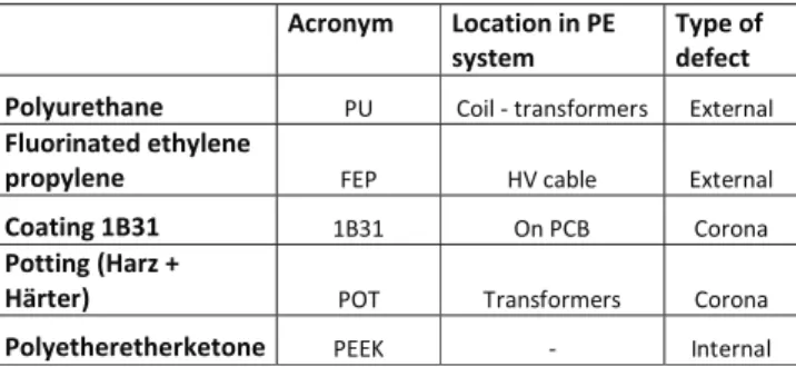
A non-exhaustive list of materials used in aerospace PE systems was established in order to create representative samples. Table 1 summarized the different materials used.
Table 1: summary of the different materials used
! Acron m " #ocation"in"$%" s stem" T &e"o'" de'ect" $ol uret(ane "# $%&'!( )*+,-.%*/0*- 12)0*,+'
)luorinated"et( lene" &ro& lene"" 31"! 45!6+7'0! 12)0*,+'! Coating"*B+*" 89:8! ;,!"$9! $%*%,+! $otting",-ar."/" -0rter1 ";<! <*+,-.%*/0*-! $%*%,+! $ol et(eret(erketone "11=! (! >,)0*,+'! B. Measurements results
This section details the results obtained under AC and Pulse voltage. DC voltage is a specific case that is treated afterwards. Before each test the relative humidity and the ambient temperature of the room are recorded.
1) Filtering influence
This section describes the influence of filtering on PD detection on samples submitted to AC and pulsed voltage. At atmospheric pressure, whatever the bandwidth of the filters, there is almost no difference on PDIV values whereas at low pressure, PDIV increases with the increase of the filters’ cut-off frequency. The second step consists to determine the best detection method under AC voltage (classical method, Rogowski coil, new method without filter). A comparison of the PDs levels between the different detection methods may be achieved on the point to plane samples. Pulses detected using the classical detection system have a magnitude up to 1.72V. This paricularly high value is due to a pre-amplifier which is set to its maximum value. The pulses measured thanks to the rogowski coil show a magnitude up to 190mV and the coaxial cable without filter up to 20mV. But it must be
reminded that the main objective of this work is to detect PD in a running PE system. Under such conditions, it is not possible to use the classical detection system whereas the Rogowski coil and the coaxial cable can be inserted into a converter for PD measurements.
On the other hand, when trying to detect PDs under PWM-like voltage, the well-known issue associated to the switching noise appears: the current linked to the high dV/dt signals makes any PD detection difficult. In this case, filtering is necessary. For this reason four different filters are compared in this study. Let’s call them filter 1, 2, 3 and 4.The most efficient filter for noise suppression must be determined. Figures 8, 9 and 10 represent the results of the measurements of a twisted pair of enameled wire and show many pulses. Among them, it is worth to distinguish those related to the switchings from those related to PDs. Since the switching noise has a linear behavior with the voltage increase, the concept of linear behavior is used assuming that the amplitude of the impulses proportionally follows the amplitude of the power source contrary to PDs signals. Hence, for voltage values varying from zero to PDIV, only the pulses associated to switching are detected. For voltages equal or larger than PDIV, PD pulses are added to switching noise. These pulses present a non-linear behavior with the voltage and can therefore be considered as PDs.
Moreover, Figure 8 and 10 shows that, when PDs occur, the Rogowski coil, the coaxial cable without filtering, and the coaxial cable with filter 1 and 2 detect four pulses. For voltage below PDIV no pulses are measured with filters 3 and 4 (Figure 9). When PDs occur, only two pulses are measured during each rising fronts of the power signal with the filter 3 (Figure 10). Furthermore, it is important to note that whatever the voltage magnitude (below or above PDIV), no pulses are measured with filter 4. This detection methodology is applied on the different samples and same results are obtained. From these measurements, filter 3 appears to be the best trade-off for PD detection and noise reduction under PWM voltage. The filters 1 and 2 do not suppress the switching noise whereas the filter 4 suppresses everything, including PD signals.
Figure 8: PD and switching noise occuring simultaneously (Rogowski, Coaxial cable without filtering, Filter 1)
Figure 9: Before PDs occur, only switching noise are visible (Filter 2, Filter 3, Filter 4)
Figure 10: Partial discharges and switching noise occuring simultaneously (Filter 2, Filter 3, Filter 4)
2) DC voltage
PD measurements under DC voltage are a special case. After a first PD, the required time to get a new one can be very long (several hours). Pulses are therefore randomly measured in time with a very low repetition rate. That is why PD measurements under DC voltage are quite complex.
Nevertheless some tests are performed on samples using the setup described in figure 7.
During these measurements some pulses are detected (One every test specimen tested). But the difference between PD and external noise is hard to do.
As a conclusion, since the repetition rate of PD under DC voltage is very low and since the only way to ignite them is to reverse the polarity (which currently is not happening in aerospace converter) our efforts will be focused on AC and pulses voltages where recurrent discharges of high magnitudes can occur.
V. CONCLUSION
This paper is the first step of a larger study to investigate an aerospace Power Electronics converter taking into account the possible existence of partial discharge phenomenon. A simple PD detection method is investigated and shows very interesting results as regards PD detection.
The main conclusion of this paper is the efficiency of the method. A simple and stripped coaxial cable is able to detect PDs during AC conditions and, by adding filtering, PD events can be dissociated from switching noises under PWM-like voltage. Among the different possibilities, the filter 3 proved to be the most efficient.
The efficiency of the PD detection under DC has not been demonstrated since electrical discharges are difficult to trig. This first study allows us to move to the next step of our work: PDs measurements on the high voltage components of an aerospace P.E systems (IGBT, Capacitors, Diode, PCB, …).
REFERENCES
[1] W. G. Dunbar, D. L. Schweickart, J. C. Horwath, and L. C. Walko, “High frequency breakdown characteristics of various electrode geometries in air,” in Power Modulator Symposium, 1998. Conference Record of the 1998 Twenty-Third International, 1998, pp. 221–224. [2] F. Koliatene, T. Lebey, J.-P. Cambronne, and S. Dinculescu, “Impact of
the aeronautic environment on the Partial Discharges Ignition: A basic study,” in Conference Record of the 2008 IEEE International Symposium on Electrical Insulation, 2008. ISEI 2008, 2008, pp. 603– 606.
[3] I. Christou and I. Cotton, “Methods for partial discharge testing of aerospace cables,” in Conference Record of the 2010 IEEE International Symposium on Electrical Insulation (ISEI), 2010, pp. 1–5. [4] A. Brockschmidt, “Electrical environments in aerospace applications,”
in Electric Machines and Drives, 1999. International Conference IEMD ’99, 1999, pp. 719–721.
[5] T. Billard, T. Lebey, and F. Fresnet, “Partial discharge in electric motor fed by a PWM inverter: off-line and on-line detection,” Dielectr. Electr. Ldots, Jan. 2014.
[6] T. Billard, T. Lebey, A. Belinger, and N. Naude, “On the nature of the discharges in samples fed by bipolar pulse like voltage and its possible impact on the detection of partial discharge in machines fed by inverter,” \ldots, Jan. 2014.
[7] R. Bartnikas and E. McMahon, Eds., Engineering Dielectrics Volume I Corona Measurement and Interpretation. 100 Barr Harbor Drive, PO Box C700, West Conshohocken, PA 19428-2959: ASTM International, 1979.
[8] M. G. Danikas, “The definitions used for partial discharge phenomena,” IEEE Trans. Electr. Insul., vol. 28, no. 6, pp. 1075–1081, Dec. 1993. [9] ASTM D2307-05, “Standard Test Method for Thermal Endurance of