Publisher’s version / Version de l'éditeur:
Canadian Geotechnical Journal, 11, 4, pp. 531-553, 1974-11
READ THESE TERMS AND CONDITIONS CAREFULLY BEFORE USING THIS WEBSITE. https://nrc-publications.canada.ca/eng/copyright
Vous avez des questions? Nous pouvons vous aider. Pour communiquer directement avec un auteur, consultez la première page de la revue dans laquelle son article a été publié afin de trouver ses coordonnées. Si vous n’arrivez pas à les repérer, communiquez avec nous à PublicationsArchive-ArchivesPublications@nrc-cnrc.gc.ca.
Questions? Contact the NRC Publications Archive team at
PublicationsArchive-ArchivesPublications@nrc-cnrc.gc.ca. If you wish to email the authors directly, please see the first page of the publication for their contact information.
NRC Publications Archive
Archives des publications du CNRC
This publication could be one of several versions: author’s original, accepted manuscript or the publisher’s version. / La version de cette publication peut être l’une des suivantes : la version prépublication de l’auteur, la version acceptée du manuscrit ou la version de l’éditeur.
Access and use of this website and the material on it are subject to the Terms and Conditions set forth at
Behavior of circular footings and plate anchors in permafrost
Ladanyi, B.; Johnston, G. H.
https://publications-cnrc.canada.ca/fra/droits
L’accès à ce site Web et l’utilisation de son contenu sont assujettis aux conditions présentées dans le site LISEZ CES CONDITIONS ATTENTIVEMENT AVANT D’UTILISER CE SITE WEB.
NRC Publications Record / Notice d'Archives des publications de CNRC:
https://nrc-publications.canada.ca/eng/view/object/?id=69e08abc-7994-4188-b8e4-39ca4634e67b https://publications-cnrc.canada.ca/fra/voir/objet/?id=69e08abc-7994-4188-b8e4-39ca4634e67b
Behavior of Circular Footings and Plate Anchors Embedded in Permafrost
B. LADANYI
Department of Mining Engineering, Ecole Polytechnique, 2500 Marie-Guyard Ave., Montreal, Quebec H3C3A7 A N D
G . H . JOHNSTON
Division ofBlrilding Research, National Research Council of Canada, Ottawa, Canada KIA OR6 Received January 4, 1974
Accepted June 3,1974
The purpose of this paper is to develop a method for predicting the creep settlement and the bearing capacity of frozen soils under deep circular loads. The theory uses experimentally determined creep parameters of frozen soil and is intended to be applicable t o the design of deep circular footings and screw anchors embedded in permafrost soils. On the basis of available experimental evidence, it was concluded that a mathematical model different from that usual in soil mechanics should be used in solving the time-dependent bearing capacity problem of such footings. The solution proposed in the paper was obtained by using the mathematical model of an expanding spherical cavity in a nonlinear viscoelastic-plastic medium with time, temperature, and n'ormal pressure dependent strength properties. For a given footing or anchor, the theory furnishes either isochronous load-displacement curves, or load-creep rate curves, or a time-dependent bearing capacity for which formulas and graphs of nonlinear elastic- plastic bearing capacity factors are supplied.
The theoretical predictability of creep rates and ultimate failure loads was checked against the results of screw anchor tests carried out by the Division of Building Research, N.R.C.C., at a permafrost site in Thompson, Manitoba. It was found that the use in the theory of the creep parameters determined by creep-pressuremeter tests performed at the site, resulted in a satis- factory agreement between the predicted and the observed behavior.
Le but principal de cette communication est de presenter une methode par laquelle il serait possible de prevoir le tassement di3 au fluage des sols geles et leur capacite portante lorsque sollicitts par des charges circulaires profondes. Cette theorie utilise des parametres de fluage determines experimentalement. Son domaine d'application est le calcul des fondations cir- culaires et des ancrages etablis profondement dans le pergelisol. A partir des rksultats experi- mentaux disponibles, on est arrive a la conclusion que, dans la solution du probleme de la capacite portante a long terme de telles fondations, il serait preferable a utiliser un modele mathematique different de celui habituellement en usage dans la mecanique des sols. La solution proposte dans cette communication a Cte obtenue a partir du modele mathematique d'une cavite spherique mise en expansion dans un milieu viscoClastique non lineaire plastique, dont la resistance mecanique depend du temps, de la temperature et de la pression normale. Pour une fondation ou une plaque d'ancrage donnee, cette theorie fournit soit des courbes isochrones charge-deplacement, soit des courbes charge taux de fluage, soit encore la capacite portante en fonction du temps. Pour cette derniere, on a fourni des graphiques donnant des valeurs des facteurs de portance, calcules en supposant un comportement non-lineaire avant la rupture.
La possibilite de prevision thtorique des taux de fluage et des charges ultimes a ete vkrifite a l'aide des rtsultats de mise en charge de plaques d'ancrage vissies dans le pergelisol. Ces essais ont Cte effectues par la Division de Recharche en Bdtiment du Conseil National de Recherches du Canada sur un site pres de Thompson, au Manitoba.
Cette comparaison a montre que le fait d'utiliser, dans la theorie proposee, les parametres de fluage determines par des essais pressiometriques speciaux, effectues sur le site, a permis de faire des previsions du comportement des ancrages qui s'approchent de la realite.
Introduction satisfied at any time during the service life of As in other types of earth materials, the the structure. I n unfrozen earth materials, allowable for a foundation or an anchor with the exception of some particular cases embedded deeply in frozen soil has to be deter- that have been solved recently by numerical mined so that the requirements for both safety methods, the two requirements have usually against failure and admissible settlement are been considered separately: The safety re- Can. Geotech. J . . 11,531 (1974)
532 C A N . G E O T E C H . J . V O L . l I , 1974
quirement has been satisfied by substituting soil strength parameters into a Prandtl-type bearing capacity theory, and the requirement of admissible settlement has been verified by substituting soil deformation parameters into a Boussinesq-type stress-distribution theory.
Moreover, in the latter case, attention has been concentrated mainly upon the compres- sibility of soil which causes the major part of the settlement. The effects of tem~erature and of undrained (deviatoric) creep have only rarely been mentioned in connection with the deter- mination of allowable foundation pressure in unfrozen soils. and are considered to be of secondary importance.
In frozen soils, obviously, the last two effects may become predominant in the determination of the allowable foundation pressures. It is well known that many relevant frozen soil parameters vary strongly with temperature, and that the undrained (deviatoric) creep of frozen soil contributes to the settlement of a foundation at least as much as the compression due to migration under pressure of unfrozen water and ice. Moreover, taking into account the observed behavior of frozen soil under footings and anchors, the use of a Prandtl-type bearing capacity theory is difficult to justify. It is believed, therefore, that in frozen soils an approach to allowable pressure determination different from that usual in unfrozen soils would be appropriate. It is the purpose of this paper to develop a method for predicting the creep settlement and the bearing capacity of frozen soil under deep circular loads. The theory uses experimentally determined frozen soil parameters and is intended to be applicable to the design of deep circular footings as well as circular plate and screw anchors embedded deeply in frozen soil.
Scope of the Theory
As mentioned in the introduction, the theory developed in this paper is intended mainly for calculating the time and temperature dependent settlement and rupture of deep circular footings in frozen soils. As creep is the main concern, a power law was adopted in the theory for defining the isochronous prefailure stress- strain behavior of frozen soil. Since the results so obtained are also of an isochronous type, the theory, in addition to serving the intended
purpose, may, in .fact, also be considered as a bearing capacity and load-settlement theory for a nonlinear elastic-plastic soil. In other words, the theory may also be used for pre- dicting settlements and failure in ordinary soils, provided, of course, that their stress- strain behavior may approximately be defined by a power law, and that their deformation is mainly due to deviatoric strains.
Another remark concerns the footing depth. Being based on a theory of cavity expansion in an infinite medium, the solution shown in this paper is valid only when the footing behavior is essentially unaffected by the free surface. For ordinary footings, according t o Meyerhof (1963), the limiting depth beyond which the effect of free surface becomes negligible is about 4 times the footing diameter for clays, and about 7-9 times the diameter for sands. An analysis of the uplift capacities of model circular footing plates in sand and clay, carried out by Meyerhof and Adams (1968), has shown that essentially the same depth limitation is valid also for deep anchor plates. It is obvious that such deep anchors, after having failed in a manner similar to deep footings, may, nevertheless, show ulti- mately a behavior more similar t o that of shallow anchors, if the pull displacements attain large values, e.g. 2 or 3 times the plate diameter. This is, however, mostly considered as unacceptable in the design.
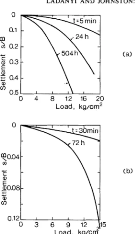
Review of Available Experimental Data Experimental information on creep-settlement and failure of frozen soil under a loaded area is at present (1973) still very scarce and in- complete. In the Russian literature, Vialov (1959), in Chapter VII of his book, reports the results of a series of small and large scale plate loading tests in frozen soils.
In one series of tests a frozen undisturbed silty clay, in blocks of 30 x 30 x 30 cm, was loaded by circular flat ended punches with diameters of 5.05, 7.13, and 10.15 cm, re- spectively. The punches were placed either on the soil surface or at the bottom of a hole in the sample. In some tests the load was kept con- stant for long time periods (from 500 to 1600 h), while in others it was increased in steps.
In another series, a number of large scale tests were performed in situ, using circular plates 50.5 cm in diameter. The soil in these
LADANYI AND JOHNSTON: CIRC
0 4 8 12 16 20
Load, kg/cm2
Load, k g / c z
FIG. 1. Isochronous load-settlement curves from circular plate loading tests (plate diameter B = 5 cm), according t o Vialov (1959).
tests was a varved clay, containing a large number of ice lenses up to 5 cm thick, with overall water content of 45%. During the tests the clay was kept at a temperature of
-0.5 to -0.6 "C.
Isochronous load-settlement curves obtained in some of these tests are shown in Fig. l(a,b). They show typical nonlinearity and time de- pendent behavior. Unfortunately, the curves cannot be used for any analytical purpose since no information on rheological properties of the soils involved has been given in the report. Nevertheless, it is interesting to note Vialov's observations concerning the mode of failure in these tests.
According to Vialov, the mode of failure of frozen soil under a punch is different from that of an unfrozen soil. Lateral heaving of the soil surface, usually observed, in a dense frozen soil, is absent in frozen soils, both in short term and in long term experiments, and in a large variety of soil types. A more important characteristic of the disturbance of the soil structure during penetration by a punch, is the
ULAR FOOTINGS IN PERMAFROST 533
appearance of cracks on the surface of the soil, directed radially from the axis of the punch; these were observed in many experiments with small punches in the laboratory and also in the field with punches of 50 cm diameter. In addi- tion, as in unfrozen soils, a solid cone or 'kernel' of dense soil was formed under the flat base of the plate during penetration. This dense kernel displaced the frozen soil radially, mainly downward and laterally, with only negligible upward movement. The formation of Prandtl-type slip surfaces was not observed in these tests.
There is very little experimental information on the bearing capacity of frozen soils available elsewhere in the literature. Indirectly, however, some information obtained in deep plate anchor tests can be considered relevant to the bearing capacity in a general way. In fact, it can well be expected that within certain limits of deformation and depth of embedment, the upward movement of a deep plate anchor would result in a soil deformation similar to that oc- curring when the same anchor or a similar rigid structure such as a footing or a pile base, is pushed into the soil.
An extensive study of such anchors in frozen soils under long term loading was carried out between 1967 and 1970 by the Division of Building Research of the N.-R.C.C. at Thompson and at Gillam, Manitoba. I t is interesting to note that the results of the anchor tests and observations made during and after the tests (Johnston and Ladanyi 1974) lead to general conclusions on the soil behavior similar to those stated by Vialov for his plate load tests. In the case of plate anchors, the isochronous pressure- displacement curves were also approximately hyperbolic in shape. After excavation, no visible failure surfaces were observed around the plate but only a cone of frozen soil was found solidly attached to the plate. A typical varved clay profile after a plate anchor test is shown in Fig. 7 of the paper by Johnston and Ladanyi (1974).
Taking into account the above mentioned experimental facts, it was felt that a mathe- matical model different from Prandtl's and coming closer to reality should be used in considering the bearing capacity of deep footings in frozen soils. The alternative model proposed in the following is based on the theory of cavity expansion, which has often been used in similar problems.
534 C A N . G E O T E C H I. J . V O L . 11. 1974
Use of Cavity Expansion Theory in Bearing Capacity Calculations
It has been known for some time that in many materials Prandtl's theory does not represent properly the observed behavior in indentation by certain kinds of punches. Many observations show that under certain conditions, which are mainly a function of the material properties and the punch geometry, instead of producing lateral shear failure as assumed by Prandtl, the punch indentation results only in a general elastic-plastic deformation of the in- dented material. In other words, the indentation creates a plastic nucleus which, even after un- loading, keeps the surrounding elastic mass in equilibrium and prevents the hole from closing. A complete solution of an elastic-plastic indentation problem is rather complex even for relatively simple assumptions on the material behavior. Until now, it has not been possible to solve it explicitly, but some particular cases have been solved by numerical methods (Duncan and Chang 1970; Girijavallabhan and Reese 1968).
Although it may be interesting to solve some important particular practical cases by numerical methods, one can hardly afford to d o so in ordinary engineering practice where, in most cases, only 'order of magnitude' solutions are sufficient and where many factors are known only approximately. At present, therefore, there may be some justification in looking for simpler mathematical models which, while not giving an accurate solution of a particular problem, enable one to visualize quite closely its most important features. In deep indentation problems such a close approximation to the true solution is given by the theory of cavity expansion. The expansion theory was first used for that purpose by Bishop et al. (1945) in connection with deep punching of metals. It has since been used with success by different authors and for various types of materials, e.g. Dugdale (1958) and Mulhearn (1959) for metals, Marsh (1964) for glass, Gibson (1950) for clays, Skempton et al. (1953) for sands, and Ladanyi (1959) for sands, for sensitive clays ( 1 9 6 7 ~ ) and for rocks (1966, 1967b).
Some recent work by Hirst and Howse (1969) and by Johnson (1970) shows clearly the de- pendence of material response to indentation on the material properties and the punch
geometry. In particular, for a variety of materials, it is found that, for a given punch geometry, the type of response depends mainly on the value of the El Y ratio, where E is Young's modulus, and Y is the yield point in simple compression. Since E / Y is equal to the re- ciprocal value of the yield strain, low EIY values imply very deformable materials, while high E / Y values correspond to rigid materials. According to Hirst and Howse (1969), four main types of deformation can be observed for indentation of real materials by hard wedges. Figure 2 indicates the regions of El Y and the wedge angle in which they may be expected t o occur.
Figure 2 shows that plastic rigid type of failure may be expected only in materials of low deformability when penetrated by sharper wedges. For blunt wedges (wedge angle z 180°), and materials of medium E / Y ratios, (i.e. 50 < E/Y < 1000), cavity expansion seems to be the closest simple mathematical model. Since this is exactly the region of E/Y valid for most cohesive unfrozen, and frozen soils, the use of the theory of cavity expansion as a proper mathematical model for penetration problems is well indicated. In comparison with Prandtl's theory which takes into account only the failure characteristics of the material, the cavity expansion theory enables one to con- sider easily the whole stress-strain behavior and its time and temperature dependence. Furthermore, it is a convenient method for predicting not only the failure loads but also a large part of the plastic settlement curve.
Transformation of Cavity Expansion Results to Deep Punching Data
The theory of cavity expansion owes its great versatility to the fact that it considers a highly symmetric problem, thus permitting relatively simple analytical solutions to be obtained, even for a rather complex material behavior. When used for a less symmetric case, such as the deep punching problem, it is obvious that it represents only one part of the solution, and, therefore, some additional as- sumptions are required. From observations made in deep punching of metals, Bishop et al. (1945) and Hill (1950) conclude that the pres- sure required to produce a deep hole in an elastic-plastic medium is proportional to that
LADANYI AND JOHNSTON: CIRCULAR FOOTINGS IN PERMAFROST
FIG. 2. Regions of operation of the different wedge indentation mechanisms, according to Hirst and Howse (1969).
necessary to expand a cavity of the same volume and under the same conditions, provided there is no friction present.
In soil mechanics, the transformation from a
cavity expansion solution to a punching problem
/
has usually been made by assuming, as proposed by Gibson (1950) that during the penetration of the punch a rigid cone (or wedge) of soil is formed at the base of the punch, the lateral
\
surface of which is acted upon by a uniformly
distributed soil pressure whose normal com-
\
ponent is equal to the cavity expansion pressure,
\
p i (Fig. 3).
\
//'
At failure, the shear strength of the soil \---dl
over the whole area of the cone is assumed to FIG. 3. Schema for transformation of a cavity be fully mobilized. From statical considerations expansion t o a deep punching ~ r o b l e m .
it is found, both for a cone and for a wedge,
that the following relationship holds and experiments, (Berezantsev 1956; De Beer [ l ] q,,
+
H = (pi,,+
H)(1+
tan4
cot a)where: q,, denotes the average pressure acting on the punch at failure, pi,, is the asymptotic value of the cavity expansion pressure acting normally upon the cone (or wedge) with the semi angle a a t the tip, 4 is the angle of internal
friction of the soil, and
[2
1
H = c cot4
in which cis the time and temperature dependent cohesion of frozen soil.
For a circular, flat-ended punch, both theory
and ~ a d a n ~ i 1961)show that a is very close to 45", enabling, for practical purposes, Eq. [ l ]
to be written as
[3
I
gas ~ias(1+
tan 4)+
cDuring the prefailure period, it may be expected that the relationship between the punching pressure and the cavity expansion pressure will also depend upon the existence of the cone and the degree of the shear strength mobilization over the conical surface. Clearly, since both of these depend upon the specific displacement of the punch, the relationship
536 C A N . GEOTECH. J . VOL. 1 1 , 1974
between the two pressures may be written in the form
where: q is the applied punching pressure, p i is the corresponding cavity expansion pressure, and 7 is a dimensionless coefficient expressing the degree of mobilization of shear strength on the cone for a given specific settlement. Based upon the results of some recent deep plate-loading tests on stiff clays (Burland et al. 1966), which are similar to stiff frozen soils, it appears that the ultimate load is attained at a settlement of about one-tenth of the plate diameter. It is therefore proposed, as a first approximation, to define 7 as:
7 = lOs/B i f s < 0.1B and
7 = 1 if s 2 0.1B
where B is the punch diameter and s is the total settlement.
For frictionless materials, Eqs. [ l ] and [4] reduce t o
[5
I
4,s = Pias+
c cot aand
[61 q = p i
+
r)C cot aFor penetrations smaller than about one- half of punch diameter, the amount of punch penetration can be evaluated approximately from the cavity expansion displacements by equalizing the displaced volumes in both cases (Johnson 1970; Ladanyi 1966).
A settlement s of a circular punch results in a volume displacement of
Since the theory of cavity expansion furnishes a relationship between p i and Vi/ Vio, Eqs. [4] and [lo] allow the corresponding pressure- penetration relationship to be estimated from the former.
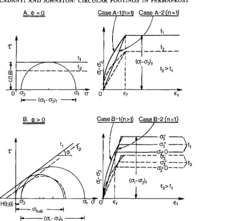
Assumptions on the Frozen Soil Behavior
A .
+
= 0 Material (Fig. 4 A ) Behavior in Prefailtae StateIt has been shown in a previous paper (Ladanyi 1972), that, for an axially symmetric case, a convenient way of expressing the axial steady state creep rate of a frozen soil, taking into account the effect of temperature is by writing
where: sc is an arbitrary creep rate, ucuo is the
creep proof stress in uniaxial compression extra- polated to 0 O C , n 2 1 is the creep exponent,
and f (6) is a temperature function which may take various forms, such as exponential, power, or even linear, for small temperature variations (Ladanyi 1972; Johnston and Ladanyi 1972). For brevity, Eq. [ l l ] can be written as
where
For constant loading and temperature con- ditions, Eq. [ l l ] can be integrated to give a n isochronous stress-strain curve valid for a constant time interval t. Experimental evidence shows that for intervals longer than about 24 h, the instantaneous or ti on of strain becomes where = B/2 is the radius of the punch. less than about 10% of the total, so that it can On the other hand, the original volume of the be neglected (Vialov 1959). The total strain is
hemisphere to be expanded by the punch then given a ~ ~ ~ o x ~ ~ a ~ e ~ ~ by (Eq. [I4] in Lad-
penetration is anyi 1972):
C81 V. = e r r i o 2 2 [I41 E ~ ~ E ~ ( ~ ) = ~ ~ ~
l o 3
if the hemisphere is assumed to have originally for brevity, Eq. [Id] can be written as the same diameter as the punch. The punch
penetration s is assumed to expand the hemi- ~ 1 5 1 sphere by Vs, so that, after expansion
where
[9
I
vi
=vio
+
vs
from which [I61 us = u cuof(6)[cctl- l l n
Y
[lo] -= 1 Behavior in Failure State
LADANYI A N D JOHNSTON: CIRCI
A . @ = O
-
JLAR FOOTINGS IN PERMAFROSTB. @ > O Case B-l(n>l) Case?-2 (n=l)
FIG. 4. Basic assumptions on frozen soil behavior used in the theory.
soil fails according to the von Mises criterion, which, for an axially symmetric case, (with
u1 > uz = u3), reduces to
where a , and u3 are the major and the minor principal stresses, respectively, and of, is the
time and temperature dependent uniaxial strength, equal to twice the soil mechanics cohesion, c:
[I81 ~ f , ( t , 0) = 2c(t, 0)
The value of of, can be expressed in terms of
time and temperature, according to Eq. 16.51 in Ladanyi (1972), by
1111 C191 f U 0) = c u o f
(2)
=where ef denotes a constant average creep failure strain, while t is the selected time parameter, e.g. the service life of the structure.
B.
4
> 0 Material (Fig. 4B) Behavior in Prefailure StateAs shown in Ladanyi (1972), a convenient empirical expression for describing the creep from the unstressed state of a frozen frictional soil obeying the Mohr-Coulomb failure crite- rion, is
where& is the flow value given by 1
+
sin4,
' = I
-
sin^
in which
4,
denotes the slope of the Coulomb failure envelope corresponding to the strain rate ;.('I = i,. All other symbols are defined as in Eq. [I 11.
As in the
4
= 0 case, one could combine Eq. [20] with a creep rupture condition to obtain a solution of the cavity expansion problem. Although this is not a very difficult mathematical exercise, it has been found that the538 C A N . GEOTECH. J . V O L . 1 1 , 1974
solution so obtained is too complicated for practical use. Moreover, as can be seen from the test results for a frozen sand-ice mixture reported by Andersland and Alnoury (1970), Sayles (1973), and Alkire and Andersland (l973), doubling or even tripling the value of a, did not have a marked effect on the shape of the pre- failure portion of the stress-strain curves, if the sample seating effect is excluded.
For the sake of simplicity it has been decided, therefore, to neglect the effect of the confining pressure on the creep rate in the prefailure state in the following analysis, i.e. to use Eq. [ l l ] instead of Eq. [20] for describing the steady state creep rate. This is analogous to adopting, in an ordinary linear-elastic case, a constant average value of the deformation modulus, instead of its true value which varies with pressure. This simplifying assumption is quite often made when solving engineering problems in soil and rock mechanics.
Consequently, the constitutive equations adopted in the following analysis for describing the behavior of a frictional frozen soil are in prefailure state (Eqs. [15] and [16]):
where afu(t, 8) is given by Eq. [19] as before. The creep strain E , in Eq. [I91 refers now
only to the unconfined state. For confining pressures different from zero, this formulation implies that E, will increase with an increasing a,, as shown in Fig. 4B. This is in agreement with the available experimental data on the behavior of saturated frozen sands in triaxial compression (Sayles 1973; Alkire and Anders- land 1973).
Proposed Method of Solution
A number of methods of solution are available at present that can be applied to solving a cavity expansion problem in materials with time de- pendent properties. The choice of a proper method depends on the properties of the material, as well as on the character and the required accuracy of the expected answer.
If the material has a linear viscoelastic behavior, the problem can be solved conve- niently by using the Laplace transform method (e.g. Gill 1970). If, on the other hand, the material has a nonlinear viscoelastic behavior, steady state creep solutions can be obtained for C221 a given steady state creep law by using the 'Hoff's analogue' (Hoff 1954) enabling a non-
where linear creep problem to be reduced to a non-
linear elasticity problem.
[23
I
as, = ~,,,f(e) [;,ti - 1" If, in addition to being nonlinear viscoelastic, is an average as value corresponding to an the material behavior is also affected by itsaverage creep proof stress a,,, which is not a time and Pressure dependent strength properties,
result of a series of unconfined creep tests as as is the case with the frozen soil, not many a,,,, but of a series of confined creep tests direct solution procedures are applicable. obtained at an average confining pressure A procedure, which is not direct, but is rel- a,,,, representative of the range to be expected atively simple, consists in expressing the de- in the problem under consideration. formation and strength properties of frozen
Behavior in Failure State soil as functions of time and temperature.
It is assumed that the frictional frozen soil Once the range of load, time, and temperature fails according to the extended Coulomb-Mohr relevant to the problem has been decided upon, criterion which, for an axially symmetric case, the problem can be solved as an ordinary non-
reduces to linear elastic-plastic problem on the basis of
time and temperature dependent stress-strain
1241
+
H= f
and strength properties.a m i n
+
H Obviously, since such a solution is based uponwhere and a m i n are the major and the isochronous stress-strain curves, which are minor principal stress, respectively, f is the not the true stress-strain curves valid for a
flow value given by Eq. [21] and monotonous loading but are deduced from
constant-stress creep curves, the resulting load- [25
1
~ ( t , 8) = c(t, 8) cot4
displacement relationship will also be of anwith isochronous type. Consequently, such a solution
can be used directly only for finding the amount [26
1
c(t, 0) = q,(t, 4 / 2 3 of creep settlement of a deep footing under aLADANYI AND JOHNSTON: CIRCULAR FOOTINGS IN PERMAFROST
Time
FIG. 5. Schematic presentation of the load-settlement-time relationship in loading tests. step-load and at a given freezing temperature.
On the other hand, for a series of step-wise load increments and temperature variations, an approximate answer can be obtained by super- position, as shown in Fig. 5.
Nevertheless, for a nonlinear creep range without failure, as well as for the whole range of creep and failure in a
4
= 0 material, it can be shown that the Hoff's analogue remains valid. In that case it is therefore possible to determine analytically the rate of cavity ex- pansion under a constant internal pressure, which is directly related to the rate of settlement of the deep footing under a step load.In all the cases solved in the following a common assumption is made that the medium is originally homogeneous and isotropic and subjected to an isotropic stress tensor p,.
As far as failure is concerned, two separate solutions are shown, one for a
4
= 0 material and another for a4
> 0 material both following a Mohr-Coulomb formulation of the failurecondition. The former is intended to cover the cases of very ice-rich soils, frozen clays, peat, and pure ice. The latter, in turn, corresponds to frozen dense sands, silts, and gravels. All the materials are assumed to be saturated with ice so that volume compression strains can be neglected in the calculation.
When the two types of materials are combined with a nonlinear and a linear prefailure be- havior, respectively, four different cases are obtained; for which the formulae for calculating creep displacements and failure loads are developed in the following. Subsequently, a recapitulation of the most important expressions for the two nonlinear cases is presented, in order to facilitate the use of the theory in the design.
Theory
In the development of the theory, the usual procedure has been followed: First, the stresses and displacements in each separate region
540 C A N . G E O T E C H . J . VOL. 1 I, 1974 around the cavity have been found. Then, by
satisfying the continuity and the boundary
L2'1
=-
PO) ( l-
&)
($)31n + Po conditions, the relationship between the pressurep i in the cavity and the corresponding radial where 01, denotes the radial stress at r = rc displacements or displacement rate of the cavity (Fig. 6 ) .
wall has been determined. It will be seen that for n = 1 the two equations
reduce to the well known Lames equations for
A . Solution for a
4
= 0 Material expansion of a spherical cavity in a linear- Case (A-I): Nonlinear Creep Behavior elastic medium.Stresses and displacements in prefailure region The corresponding displacement field is (r, < r < a). In a spherical region around the defined by
cavity extending from a radius re 2 ri to in-
u 1 3(0,, -
finity (Fig. 6), the material is assumed to be in 1301 - = -
[
PO)]^($)^
prefailure state, behaving according to Eq. [15
1.
I' 2 2no,Moreover, owing to the adopted general as-
sumptions, the conditions of equilibrium reduce where u is the radial displacement at a distance r to only one differential equation from the center of the cavity.
Failure Region (ri < r < re). Substituting the 1271 do, -+2-- 'Jr - 'JI - 0 failure condition, Eq. [17], into the equilibrium
dr r Eq. [27], integrating, and considering the
where a, is the major principal stress (radial) boundary condition a, = pi at r = r i , one gets and a, is the minor principal stress (circum- the well known equations for the stresses in the
ferential). failure region
r
For an incompressible material with a non- 1311 a, = p i - 4cln-
linear stress-strain defined by Eq. [15], the r
solution can readily be found, and has been quoted in several textbooks (Odquist and Hult 1321 1962; Hult 1966). According to this solution,
the stresses in the prefailure region are The extent of the failure region can be obtained
3/11 from the continuity of the stresses a t the inter-
1281 I = ( , - P
( )
+
Po face between the two regions. For r = re, Eqs.[28], [29], 1311, and [32] give 1331 I'e \ a,, = p i - 4c In - I'i \ 1341 0,. =
(
1-&)
( ~ , , - pol+
p0 = \ \ \ \Eliminating a,, one gets
'r-
\
I 1351 ],2 r =
Pi
-
- nI+ Ti 4~ 3
I
I PO From Eqs. [33] and [35],
'*
1361 a,, - po = 4 -cni
3/
which, substituted into Eq. [30], gives the,/ displacement at r = r,,
LADANYI AND JOHNSTON: CIRCULAR FOOTINGS IN PERMAFROST 541 A complete displacement field in the failure
zone can be obtained by the methods of in- cremental plasticity, as shown by Hill (1950). However, if only the pressure-expansion curve has to be determined, it is sufficient to know only the radial displacements at the boundaries of the region. A satisfactory answer to this problem can be obtained from geometrical considerations, and by introducing the idea of an average total volume strain in the failure region, e,,, positive for compression (Ladanyi 1963).
From the geometry of Fig. 6, by equating the volumes of the failure zone before and after the displacement ui of the inner boundary, and
asymptotic value of the expansion pressure, pi,,, is then equal to
[41] pi,, = po
+
~c 4 [ n+
In-:(s)~]
Eq. [41] can also be written aswith
N p = 1 and
or, owing to Eqs. 1161, [18], and [19], after neglecting certain small magnitudes of
higher order, the following expression can be 1441 N,, =
4
[n+
ln&]
deduced 3
Similarly, using Eq. [5] (with cot u = l), one
Vi
-
(
U i ) ' =(
1381 -= I + -
-
1 - - can get from Eq. [42] the correspondingVio I'io asymptotic punching pressure, q,,
- 1 - en,
--
1 - A, [451 gas = poNq
+
cNc where Vi and Vi, denote the current and theinitial volume of the cavity, respectively, ri and rio the corresponding radii, ui the radial displacement of the cavity wall, while A, is defined by
Substituting Eqs. [35] and [37] into Eq. [39], one gets
Since the
4
= 0 condition usually character- izes a frozen saturated clay or a frozen sand with high ice content, the average volume strain in the failure region, e,,, is expected to be very ,small and can be neglected. When A, from Eq. [40] is substituted into Eq. [38], one gets the equation of an isochronous and isothermal pressure-expansion curve of a general form Vi/Vio = f (pi-
po). This curve is valid from the moment the frozen soil starts to fail around the cavity, up to the general expansion failure of the medium. As seen from Eq. [38], this latter event can be expected to occur only asymptotically when A, tends to unity. Thewith
N, = 1 and
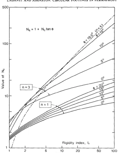
In Fig. 7 the variation of factor N,, Eq. [46], is shown for n varying from 1 to 10, and for five different values of the failure strain ef o r the ratio (2c/uS)". For n = 1, the values of Nc reduce to those valid for an incompressible linear elastic perfectly plastic material.
Pressure-settlement Behavior. For calculating the whole isochronous settlement curve, one may proceed as follows: When failure region exists, which, according to Eq. [35] occurs only when
C471 pi - po
>
-nc 4 3or, due to Eq. [6], (with u = 459, when C481
or, with Eq. 1421, when
Eqs. [38] and [40] are valid. They give for A, # 1 and A, = 1, respectively,
542 C A N . GEOTECH. J . VOL. 1 1 , 1974
the pressure-settlement curve is given according to Eqs. [lo] and [38] by
in which ui/ri is obtained by setting in Eq. [30]
a,, = p i and re = r = ri. Equation [56] be- comes then
Or, taking into account Eqs. [6] a n d [16] to ~191,
0
4 6 8 S
0 1 2 10 [58] - =
Creep exponent, n B
FIG. 7. Values of bearing capacity factor N, for 4 = 0, and for linear (case A-2) and nonlinear (case A-1)
creep.
{
3[
4nc1 3 2c
"
[SO] I--=- -
v / v i o 2
(
asx exp [3(pi4; PO) )_ n]
and
Dividing Eq. [51] by Eq. [50], one gets [52] = [l - exp
(
-4
(pi,. - Pi)]-'Vi o
Further, using Eqs. [lo], [5], and [6], one gets for the isochronous settlement curve:
or, with Eq. (45)
If the failure zone does not exist yet, which happens according to Eq. [48] when
The ambient pressure po in all settlement formulae should be considered as the average original normal pressure at the level of the punch. For example, assuming equality of horizontal principal stresses
in which p, is the total vertical pressure and KO is the at rest earth pressure coefficient. No field information is available as yet on the value of KO in frozen soil layers, but intuitively one can expect it to be larger than in the same soil when unfrozen, because of residual lateral stresses generated during freezing.
As a first approximation, one may take, therefore, KO = 1, i.e. po = p,, but lower values are also possible in the region of vertical thermal cracks.
Equations [53] and [58] give the amount of creep settlement of a deep circular punch em- bedded in frozen soil of constant temperature 8,
if a step load q is applied and maintained con- stant during a time interval t. Obviously, by varying t , one can find the whole development of settlement with time. Inversely, noting that in Eqs. [45], [54], and [58] c is a function of time, given by Eqs. [18] and [19], one can also deduce from the same equations the time neces- sary for a given settlement to be attained under a constant l o a d q. In particular, from Eq. [45]
LADANYI AND JOHNSTON: CIR( ZULAR FOOTINGS IN PERMAFROST 543 it follows that the time t o failure (infinite settle-
ment) under a load q, satisfying the inequality Eq. [48], will be
Creep Rate by the Hofl's Analogue. In order
t o find the steady state creep solution by the Hoff's elastic analogue method, it is sufficient to replace the stress-strain law, Eq. 1151, by the corresponding creep law, Eq. [ I l l , and all strains and displacements by their derivatives with respect to time. It is well known that the steady state creep stresses then remain equal to the stresses in the corresponding nonlinear elastic solution. Equations [28] and 1291 re- main valid, therefore, during the steady state creep. The radial displacement rate of the cavity wall in pre-failure stage thus becomes, according to Eq. 1301:
and the corresponding settlement rate, SIB, is obtained by substituting lii/ri into Eq. [56] instead of ui/ri. When the failure region exists, the settlement rate can only be obtained in- directly from Eq. [54], by observing that c is a function of time defined by Eqs. [18] and [19] as
Case (A-2): Linear Creep Behavior
This case is, in fact, a special case of the fore- going nonlinear elastic plastic (+ = 0) case. I n order to transform the former solution into a corresponding solution for the linear case, it is sufficient to put n = 1 in all expressions and to replace a, by the (time and temperature dependent) modulus of elasticity E. One thus obtains the classical linear-elastic perfectly plastic solution for the expansion of a spherical cavity in an incompressible medium (Bishop
et al. 1945; Hill 1950).
If, on the other hand, it is assumed, as in Bishop et al. (1945), that the material is compres- sible (v # 0.5) in prefailure state only, one gets for N,, instead of Eq. [43],
Another expression affected by the Poisson's ratio is Eq. [40] which, for v # 0.5, becomes [64] As = 2
(
E3
exp [3(pi4; P O )-
Equations [52]-[54] remain unchanged. In the prefailure period of cavity expansion one gets instead of Eq. [57] a settlement formula based on LamC's theory:
It is interesting to compare Eq. 1651 with the analogous Boussinesq equation for the settle- ment of a rigid circular load on the surface of an elastic solid
At the surface po z 0, and for small strains,
(7 = O), Eq. [65] becomes
Comparing Eq. [66] with Eq. [67] leads t o the conclusion that they will predict equal settle- ments provided v = 0.363. For v < 0.363, however, Boussinesq formula, Eq. 1661, predicts slightly larger settlements than Lame's formula, Eq. [67], while for v > 0.363, the settlements calculated from LamC's formula become larger, up to a maximum of 27% at v = 0.50.
B. Solution for a
4
> 0 MaterialCase ( B - I ) : Nonlinear Creep Behavior
Stresses and Displacenlents in Prefailure
Region. Since the behavior of the material in
prefailure state is assumed to be given by Eq. 1221 which is mathematically analogous to Eq. [15], the solution in the outer prefailure region around the cavity is identical to that in Case A, Eqs. [27]-[30], the only difference being that a, should now be replaced by a,, according t o Eq. [23].
Stresses and Displacements in Failure Region.
Following the same reasoning as in Case A, but using Eq. [24] as the failure condition, one gets a corresponding set of expressions for stresses and displacements in the failure region
544 C A N . GEOTECH. J . V O L . 1 1 , 1974
around an expanding spherical cavity in a fric- and tional frozen soil.
178
I
Nc = (Nq-
1) cot4
StressesFrom the condition of continuity of stresses at the interface between the failure and non- failure regions, the extent of the failure region is [70]
L =
[(k-
n)(pi+
H ) ] ~ I ~ ( ~ - ' )r i k(po
+
H)where
and the displacement at the interface
As in Case A, the displacement of the cavity wall can be determined from Eqs. [38] and [39]. After substituting Eqs. [70] and [72] into Eq. [39], the following is obtained:
The asymptotic expansion pressure, pias, is obtained by setting A,' = 1, which yields ~ 7 4 3 Pias
+
H - - N, =- kPO f H k - n
If the right-hand side of Eq. [74] is called the 'cavity expansion factor' and denoted by N,, Eq. [74] can be written as
175
I
pias = poNp+
H(Np-
1)The corresponding asymptotic punching pres- sure is then
For graphical representation of typical values of the Nc factor, it has been found convenient to write the complete equation for Nq in the form (with e,, taken equal to zero):
[79] N~ = (1
+
tan 4)(c)
"(k~, tan +)"Ikwhere I, is a generalized 'rigidity index', analo- gous to that introduced by VesiC (1963) for the linear-elastic-plastic case of cavity expan- sion.' For the nonlinear-elastic-plastic jncom- pressible case considered here, I, is defined by
I, = 2"a cot
4
PO
+
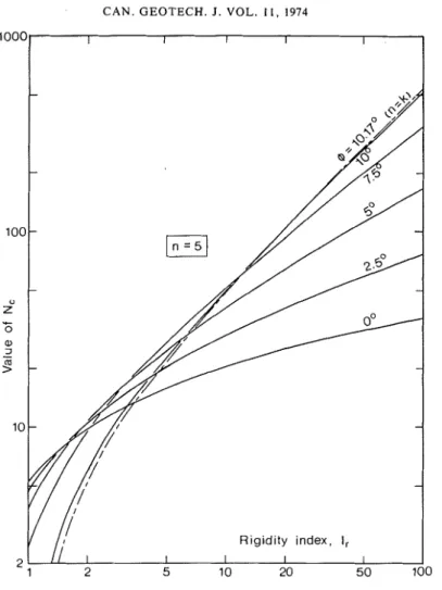
H) which can also be written asFigures 8-10 show the variation of the Nc factor with I, for n = 1, 3, 5, and 7, and for several values of angle
4
from4
= 0 to +,,,, which is obtained at the limit of validity of the.
formula, i.e. for k = n.For the
4
= 0 case, I, becomes183
1
I, = 2us/3cso that, Eq. [46] can also be written as
Pressure-settlement Behavior
Failure Region Exists. Inspecting Eq. [70] and taking into account Eq. [4] shows that the failure region will appear around the cavity as soon as
k
'+
H ( ~ + v t a n + ) - l > -P ~ H k - n
where (for cot u z 1) 'In a more recent publication, Vesif (1972) uses a new 177
I
Nq = Np(l+
tan4)
I, value. which is exactly one half of the originally proposed I,LADANYI AND JOHNSTON: CIRCULAR FOOTINGS IN PERMAFROST 545
Rigidity index. I,
FIG. 8. Values of bearing capacity factor N, for 4 > 0 and for n = I and 3.
which, obviously, is possible only if Combining Eq. [87] with Eq. [86] shows that, in terms of punching pressure, the condition,
k
> nEq. [85], for the existence of failure region be- If the above conditions are fulfilled, the iso- comes:
chronous settlement curve can be calculated as follows :
From Eq. [75]:
P o
+
H = (pias+
H>/Npso that
On the other hand, dividing Eq. [4] by Eq. [I 11 (with a NN 45')
When the failure region exists, Eqs. [38] a n d [73] are valid. Thus, proceeding similarly as in Case A when developing Eq. [52], one gets from Eqs. [38] and [73]:
where R is given by the left-hand side of Eq. [87] for cavity expansion and by the right-hand side of Eq. [87] for the punching problem, or alterna- tively by
C A N . GEOTECH. J . VOL. 1 I , 1974
' O o 0 0
FIG. 9. Values of bearing capacity factor N, for 4 3 0 a n d n = 5.
[go] R =
(*)(
'
+ tan/
)
However, the settlement can, nevertheless, bep o + H 1 + y t a n / calculated from the nonlinear-creep theory as in Case A, by using Eq. [57] in which a, should
+ N c tan
4)
be replaced by a,,, and (pi - po) by Eq. [4]:Taking Eq. [lo] into account, the equation of q + H
an isochronous creepsettlement curve becomes: 1931 Pi - PO = 1 + tan
4
- (PO+
H )In ice-rich frozen soils, the volume strain e,, may usually be neglected.
Failure Region does not Exist. According to Eq. [70], if either k
<
n, orq + H k
11921 ---- p o + H k - n
<-
(1+
7 tan$1
there will be no failure region around the ex- panding cavity for any pressure, and con- sequently no asymptotic expansion pressure.
Obviously, at small loads (q << q,,) and, there- fore, small settlement (y
=
0), it is sufficiently accurate to take[94
I
Pi - Po"
9 - PoCase (B-2): Linear Creep Behavior
Again, this case is a special case of the fore- going nonlinear case (B-1). In order to get the corresponding solution for the case (B-2), it is sufficient to take n = 1 and to replace a,, by the (time and temperature dependent) modulus of elasticity E. One gets then an incompressible version of the well known linear elastic per-
LADANYI AND JOHNSTON: CIRCULAR FOOTINGS IN PERMAFROST 547
FIG. 10. Values of bearing capacity factor N, for 4
>
0 and n = 7.fectly plastic solution for an expanding spherical cavity in a frictional medium (Skempton et al. 1953; Vesid 1963).
Recapitulation
In order to facilitate the use of the proposed theory in the design of deep circular footings and anchors in permafrost, the most important for- mulae for the two nonlinear cases, A-1 and B-1, are recapitulated in the following.
Case A-1:
4
= 0 Material; Nonlinear CreepBehavior
Basic Soil Parameter
The time and temperature dependent cohesion,
c, defined by
Asymptotic Punching Pressure
where
Nq = I
Some values of the Nc factor, for 1 I n I 10 and 0.01 5 ef 5 0.12, are shown graphically in Fig. 7.
Isochronous Pressure-displacement Curves
If
[55
I
4-
po<
4 4 4 3+
77) there is no failure zone, and548 C A N . G E O T E C H . J . VOL. 1 1 , 1974
[48
I
q - p0 > 4 4 4 3+
7,) [231 a,, = [ a , , ~+
as,,(fc - 1)11(~,t)-'~"the failure zone exists, and and (pi - p0) by
q + H 1541 SIB
=L{[l
3-
exp:(-+ c 1 C931 pi-
p0 = + 7, tan + - (p0+
HI If both k > n and - 7 ,-
Nc)]-l-
l} q + H >- k [851 ~ . p k - n (1+
7, tan +) Time to Failure Under a Load qCase B-I:
+
> 0 Material; Nonlinear Creep BehaviorBasic Soil Parameters
The angle of internal friction
Q
and the timethe failure zone exists, and
where
-
and temperature dependent cohesion, c, defined NOTE: In all these expressions, a,,,, = o,,, f(O),
by denotes the creep modulus of the frozen soil,
1 I n
[lo21 C - % r which is equal to the uniaxial (unconfined)
2 Jf(:,t) compression strength of the soil at a tempera-
where ture of 6 degrees Celsius below 0 "C, and at
a strain rate = E,. ' The values of u,,,,, n,
[21] f = (1
+
sin +)/(I - sin4)
4,
ande f have to be determined experimentally, Additional, deduced, parameters: either by means of laboratory tests, as described 125
I
H = c cot+
in Ladanyi (1972), or by using a field technique, such as the one shown by Ladanyi and Johnston171
I
k = 3f/2( f - 1) (1973).[82] = g(l + f i t a n + ) - I Comparison of Theoretical Predictions with
C
Experimental Results
Asymptotic Punching Pressure The theory proposed in this paper is well
~761 4as = poNq
+
cNc pull load, of deep circular anchor plates em- suited for predicting the behavior, under awhere (for e,, = O), bedded in permafrost. In fact, an extensive
study of such anchors under long term loading [79] N, = (1
+
tan +)(+)lJk(kI, tan +)"Ik was carried out between 1967 and 1970 by thex (1 - n/k)("lk-') ~781 N, = (N, - 1) C O ~
4
Some values of the N, factor, for 1
<
I, 5 100 and n = 1, 3, 5, and 7, are shown graphically in Figs. 8, 9, and 10.Isochronous Pressure-displacement Curves If either k < n, or
q + H k
C921 - <-
p o + H k - n (1
+
7, tan4)
there is no failure zone, and the creep displace- ments should be calculated by using Eq. (57), in which a, should be replaced by a,,, defined byDivision of Building Research of the National Research Council at Thompson, Manitoba. The study was followed in 1971 by a thorough investigation of creep and time dependent strength properties of the frozen soil a t the same site by means of specially designed pressuremeter tests.
A detailed description of the screw anchor tests is given in the paper by Johnston and Ladanyi (1974), while some typical pressure- meter test results obtained at the site have been presented in a paper by Ladanyi and Johnston (1973).
A detailed description of the site and soil conditions was given in a recent paper by
LADANYI AND JOHNSTON: CIRCULAR FOOTINGS IN PERMAFROST 549 Johnston and Ladanyi (1972), describing grouted the following form was found convenient rod anchor tests that were performed at the (Johnston and Ladanyi 1974):
site during the same period of time. Con-
sequently, only some basic information neces- [95] S = S,C 4net
+
YD
sary for understanding the comparison need be qas,net
-
4netrepeated here. where J is the displacement rate in in./min,
Soil Conditions at the Test Site S, is an arbitrary displacement rate,
C
is and Within the depth interval investigated, i.e. experimental dimensionless parameter, and between 5 and 14 ft (1.50 and 4.20 m), the soil qne, is the net pressure defined bywas a varved clay of low to medium plasticity, [96] 9net = 4 - YD composed of dark brown clay layers from 0.5 to
1.0 in. (12 to 25 rnm) thick, and tanmcolored silt 4 denoting the Pressure. Numerical layers increasing in thickness with depth from data for the Dy the overburden Pressure
1 .O to 3.0 in. (25 to 75 mm). yD, the parameter
C,
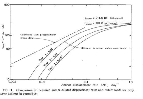
the asymptotic ultimate The most significant ice segregation was pressure q,,,,,,, and the time to failure for the found in the top 13 ft (4.20 m) and was usually three anchor tests, are given in Table 1 (Johnston associated with the dark layers. Ice lenses were and Ladanyi 1974).mainly horizontal and varied in thickness from Figure 11 shows for the three tests, according hairline to a maximum of about 0.5 in. (12 mm). to this generalized information, the creep rates Permafrost temperatures at depths between versus qn,, plot and the value of the average 5 and 30 ft (1.50 and 9.00 rn), were fairly 'ltimate pressure, qas,net = 201 P . ~ . ~ . (14a1 kg/ uniform, varying between 31.5 and 31.8 O f ? cm2). The qas,net? which to
(-0.10 and -0.30 "C) throughout the year. an infinite displacement rate is, obviously, the ultimate pull-out resistance of the anchors. Some Typical Results of Screw Anchor Tests In order to compare the observed behavior A total of 12 screw anchors were installed of the anchors with theoretical predictions, use at the site in 1967. These were tested during Was made of frozen soil creep information ob- 1969 and 1970. Ten of the screw anchors had tained by pressuremeter tests described in single helices ranging in diameter from 8 to L a d a n ~ i and Johnston (1973). In that Paper, 15 in. (20 to 38 cm). The anchors were installed it was shown that the results of stage-loaded at depths varying from 8 to 14 ft (2.40 to pressuremeter creep tests could be expressed by a 4.20 m). The other two were double helix creep law of the form
anchors.
Three typical tests on anchors 1-ION, 2-ION, and 1-IOHP have been selected for comparison purposes. The three were single helix anchors having a diameter B = 10 in. (25.4 cm), and were installed at depth, D, of 9 to l o f t (2.70 to 3.00 m). All were stage loaded to failure in 7-8 stages, giving an average total test duration of about 40 h.
In order to put the test results in a more general form, the data were treated in a manner similar to that proposed by Hult (1966) and Ladanyi (1972) for generalizing the steady-state creep data. In other words, for each stage, the pseudo-instantaneous displacement and the steady-state creep rate were determined and plotted against the applied load.
As expected, the resulting creep and dis- placement functions were both of a hyperbolic type. In particular, for steady-state creep rates,
where E ~ ( " ) and ue are equivalent creep strain and equivalent stress respectively, b, n, and a,
are material constants for a given temperature, and
<'
is an arbitrary strain rate. A pressure- meter test being of relatively a short duration, Eq. [97] is of the primary creep type (i.e. b < 1). When extrapolating this kind of data to long term creep processes, it is more convenient, and on the safe side, to transform the data to a steady-state creep, by assuming that the creep rate remains constant after a given period of primary creep. In order to d o that, it is only necessary to differentiate Eq. [97] with respect to t and to put t = to = const. This gives[97a] i,(") = b(i,'~b)~t,b- '(cr,/ac>" = ic(cre/ u,>" For the two pressuremeter tests, numbers 9-1 and 10-1, used for the comparison, the
550 CAN. GEOTECH. J . VOL. 1 1 , 1974
I
qaS,net = 21 1.5 p.si. (calculated)I
."
0.002 0.01 0.1 1 .o
Anchor displacement rate S/B , day-'
FIG. 11. Comparison of measured and calculated displacement rates and failure loads for deep screw anchors in permafrost.
TABLE 1. Numerical data for the three anchor tests
Diameter Depth Time to
Anchor B D YD 3, qas.oe, failure
No. (in.) (ft) (p.s.i.1 (in./min) C @.s.i.) (h)
1-10N 10 10.0 8.67 l o 4 36.7 203.8 72
2-ION 10 9.3 8.06 l o 4 57.7 192.0 23
1-1OHP 10 9.0 7.80 l o - 5 92.0 202.2 22
following average values of the parameters were obtained: n = 2.095, b = 0.633, o, = 69p.s.i. (4.8 kg/cm2), for ;,' = min-'.
Since it was found that the creep curves in anchor tests became linear after about 2 h, to = 120 min was adopted, and the following creep rate equation was deduced from Eq. [99]
Sufficient information is, therefore, available to complete Eq. [61], since from Eq. [99]
;., = mine' = 0.144 day-', a,,, = 69 p.s.i. (4.8 kg/cm2) (for the same temperature) and
n = 2.095. Therefore.
with (pi - p,) in pounds per square inch. The corresponding displacement rate SIB was then obtained by substituting zii/ri into Eq. [56] and
by taking into account that, according to Eq. [4], for a given pi - p,, the corresponding net pressure is given by
In the calculation, 7 was taken to vary linearly from 0 at q - p , = 0 to 1.0 at q - p , =
100 p.s.i. (7 kg/cm2) at which s/B
=
0.10 was attained in the tests.In order to be able to determine the value of H , the long term strength of the soil should be known. The cohesion, c, corresponding to the average time to failure tf = 40 h = 2400 min in the three anchor tests, was calculated from the formula (Eqs. [19] and [26])
LADANYI AND JOHNSTON: CIRCULAR FOOTINGS IN PERMAFROST 551 For frozen vaned silt-clay, an angle of friction takes into account the nonlinear viscoelastic of
4
= 15" may be assumed, while a failure character of the frozen soil, as well as the fact strain of E~ = 0.10 was observed on stress-strain that its strength is a function of the time, thecurves in pressuremeter tests. temperature and the normal pressure. The
This yields theory is intended primarily to provide all
0 . 4 7 7 3 necessary design information for deep footings
-
= 2
&
( 2 4 0 ~ ~ 0 1 0 - 4 )-
embedded in permafrost, but it can also be used for predicting the deviatoric nonlinear elastic17.45 p.s.i. (1.22 kglcm2) and plastic settlement of footings in ordinary
and soils with negligible volume strains.
The predictive capacity of the theory was H = c cot
4
= 17.45 x 3.732 checked against the results of screw anchor tests = 65.12 p.s.i. (4.56 kg/cm2) carried out at a permafrost site in Thompson, Manitoba. It was found that the use in the theory The resulting displacement rate versus q,,, of pressuremeter-determined creep parameters relationship is shown dashed in Fig. 11. Since of the frozen soil at the site, resulted in satis- the case without failure zone was assumed in the factory agreement between the predicted and the calculation, the validity of this line extends only observed behavior of three typical anchors. to about 145 p.s.i. (10.2 kg/cm2), according t oEq. 1921.
In order to determine the asymptotic ultimate Acknowledgments
pull-out resistance, the value of I, should first This work was initiated during the first be calculated from Eq. [82]. For p, =
yD
= author's 1970 summer term as a visiting profes- 8.67 p.s.i. (0.6 kg/cm2), one gets: I, = 4.596. sor at the Division of Building Research, Since k = 3.658 (Eq. [71]), one gets N , = 3.049 National Research Council of Canada, Ottawa, (Eq. [741), N, = 3.866 (Eq. [77]) and N , = 10.70 Canada.(Eq. [78]). The N , value can also be obtained The authors wish to acknowledge the con- by interpolation from Fig. 8. The asymptotic structive discussions and criticisms by members pressure is then, by Eq. [76], gas = 220.17 p.s.i. of the Geotechnical Section, especially Dr. L. W.
(15.41 kg/cm2), and q,,,,,, = 211.50 p.s.i. (15.1 1 Gold, Head of the Section, who made a number
kg/cm2). of helpful suggestions for improving the manu-
The last value has been plotted in Fig. 11 script. and is seen to agree very well with the average
ultimate pulling resistance of the three anchors, ALKIRE, B. D., and ANDERSLAND, 0. B. 1973. The effect
qas,net = 201 p.s.i. (14 kg/cm2). of confining pressure on the mechanical properties when the observed and the o f sand-ice materials. J. Glaciol. 12(66), pp. 469-481.
ANDERSLAND, 0. B., and ALNOURI, I. 1970. Time de- predicted behavior of the anchors, it is seen pendent strength behavior of frozen soils. Proc. that the results obtained by substituting the A.S.C.E. 96(SM4), pp. 1249-1265.
pressuremeter data into the theory, come close BEREZANTSEV, V. G. 1956. Bearing capacity of founda- to, but slightly underestimate the creep rates tions at an axially symmetric state of stress. (In and overestimate the ultimate strength of the Russian.) Gostroyizdat, Moscow, U.S.S.R. pp. 84-88. Proc. Conf. Soil Mech. Found. Eng., anchors. This is thought to be due to the fact BEHOP, R. F., HILL, R., and Mom, N. F. 1945. The that the soil above the anchors has been dis- theory of indentation and hardness tests. Proc. turbed by their installation- and may therefore ~ h y s . soc., Lond. 57(3), pp. 147-159.
be expected to be slightly weaker than the natural BURLAND, J. B.7 BUTLER, F. G . , and D'JNIcAN, P. 1966. The behavior and design of large diameter bored soil tested by the pressuremeter. piles in stiff clay. Proc. Symp. Large Bored Piles,
London, Engl. pp. 51-71.
Conclusions DE BEER, E. E., and LADANYI, B. 1961. Etude experi- mentale de la capaciti portante du sable sous des A method for predicting the creep settlement fondations circulaires Ctablies en surface. Proc. and the time dependent bearing capacity of 5th Int. Conf. Soil Mech. ~ o u n d . ~ n g . , paris,
France. 1, pp. 577-585.
frozen under deep loads has been DUGDALE, D. S. 1958. Vickers hardness and compressive developed and compared with available experi- strength. J. Mech. Phys. Solids. 6, pp. 85-91. mental information. The proposed solution DUNCAN, J. M., and CHANG, C. Y. 1970. Nonlinear