HAL Id: hal-03032130
https://hal.archives-ouvertes.fr/hal-03032130
Submitted on 5 Dec 2020HAL is a multi-disciplinary open access archive for the deposit and dissemination of sci-entific research documents, whether they are pub-lished or not. The documents may come from teaching and research institutions in France or abroad, or from public or private research centers.
L’archive ouverte pluridisciplinaire HAL, est destinée au dépôt et à la diffusion de documents scientifiques de niveau recherche, publiés ou non, émanant des établissements d’enseignement et de recherche français ou étrangers, des laboratoires publics ou privés.
applications
G. Teyssedre, Thi Thu Nga Vu, Nugroho Adi, Séverine Le Roy, Ngapuli
Sinisuka, Christian Laurent
To cite this version:
G. Teyssedre, Thi Thu Nga Vu, Nugroho Adi, Séverine Le Roy, Ngapuli Sinisuka, et al.. Design-related space charge in insulations for HVDC applications. International Conference on Science and Technology„ Nov 2016, Hanoi, Vietnam. pp. 1-7. �hal-03032130�
172
DESIGN-RELATED SPACE CHARGE IN INSULATIONS
FOR HVDC APPLICATIONS
Gilbert Teyssedre1, Thi Thu Nga Vu2, Nugroho Adi3,
Sèverine Le Roy1, Ngapuli Sinisuka3, Christian Laurent1 1Université P. Sabatier – CNRS, Toulouse, France
2
Electric Power University, Hà Nội, Việt Nam
3PLN Indonesia, Jakarta, Indonesia 4Bandung Institute of Technology, Bandung, IndonesiaAbstract: In the field of energy transport, High Voltage DC technologies are booming at present
due to the more flexible power converter solutions along with needs to bring electrical energy from distributed production areas to consumption sites and to strengthen large scale energy networks. These developments go with challenges in qualifying insulating materials embedded in those systems and in the design of insulations relying on stress distribution. Our purpose in this communication is to illustrate how far the field distribution in DC insulation systems can be anticipated based on conductivity data gathered as a function of temperature and electric field. Outputs of the model are compared to measured field distributions using space charge measurements techniques. It is shown that the main features of field distribution on model cables put under thermal gradient can be anticipated based on conductivity data. However, space charge build-up can induce substantial electric field strengthening when materials are not well controlled.
Keywords: Space charge, insulation, HVDC cable, PEA method
1. INTRODUCTION
For energy transport purpose, the field of High Voltage DC technologies is booming at present due to the more flexible power converter solutions along with needs to bring energy from distributed production areas to consumption sites, including sub-sea links, and to strengthen large scale energy networks [1]. The materials used for electrical insulation in the corresponding systems, being for cables, converters, bushings, etc. have specific requirements as the field distribution does not follow the same rules as for AC. Indeed, in the case of HVAC stress, the stress distribution can be relatively well anticipated as it follows a capacitive distribution, i.e. function of the permittivity of materials. When switching to the DC case, the distribution is no longer capacitive in steady state, and moves to resistive field distribution after passing through a transient regime where space charges settle [2]. Anticipating the field distribution is therefore quite challenging, all the more that polymeric materials that are more and more used in electrical insulation systems, have a substantial dependence in temperature of the electrical conductivity and exhibit non-linear field dependence of conductivity in a field range (c.a. 10 kV/mm and beyond) corresponding to service fields. Besides, they undergo charge trapping which further makes uncertain the prediction of field distributions. The consequences of such features are local reinforcement of the electric field, representing possible weak points of the material with early breakdown. The second issue, connected to space charge build-up, resorts to the possible involvement of electrical charges in the long-term ageing of materials. Addressing the above problems needs research and skills in many scientific aspects resorting to:
173 the development of materials with improved performances regarding targeted applications; the development of physical models for the material behavior: how charges are generated,
stored, and transported;
the development of techniques, particularly charge distribution measurement techniques, relevant to the geometry and to the thermal and electrical stresses that are encountered; the proposal for materials assessment methodologies for the application: This means that
relevant quantities have to be measured and figures of merit for materials provided in order to make systems more safe;
the implementation of engineering models for stress distribution estimation.
In this contribution, we are mostly concerned with polymeric materials used as insulation in HVDC cables. Polyethylene, particularly crosslinked polyethylene, has been used for over 30 years as insulation for HVAC cables, rated up to 500 kV, and now the feedback on their sustainability is well established. We present some results illustrating how the above items are treated for this application.
1. TECHNIQUES AND METHODOLOGIES FOR SPACE CHARGE ASSESSMENT
Historically, space charge measurement techniques have been implemented before the reconsideration of HVDC energy transport. Several of these direct and non-destructive techniques, commonly known as "influence" or "stimuli" methods [3-5] have been developed. They do really represent essential tools for assessing materials in HVDC applications. They are based on the application of a mechanical, thermal or electrical stimulus which perturbs the electrostatic equilibrium in the measured sample, giving birth to a transient response function of the charge distribution across the sample. While they have been applied for long on flat insulating samples of thickness typically larger than 100µm, for various electrical engineering applications, there is still a very important matter, with the challenge of being able to determine the real field distribution in cable structures. In this respect, two techniques emerge, based on either a thermal perturbation: the Thermal Step Method, or a field pulse perturbation, the Pulsed Electroacoustic –PEA method. The challenges now are to upscale these techniques for high voltage environment measurement, on full size cables of several cm thick insulation [5].
We briefly describe here the PEA method in its version for cable geometry. The method uses a fast varying electric stress as the perturbation [6]. This produces a variation of the electrostatic force acting on each charge and thus creates elastic waves propagating from the charges and proportional to their density. These waves travel across the insulator at the speed of sound and can be detected by a piezo transducer. The measured signal is an image of the charge distribution since elastic waves arrive at a time depending on the distance between the charges and the transducer. The spatial resolution of the method depends on the thickness of the sensor and the general bandwidth of the system, which is of the order of 100 MHz. Features of the method are the possibility of making acquisition with stress either on or off, its excellent time resolution, and its relative lightness. A typical experimental arrangement for cables is shown in Fig. 1 [7]. It consists of a cable sample with a measurement device composed by a PEA cell including piezo sensor and amplifier, a DSO, a HVDC generator and a pulse generator (50 ns width, 10 kHz frequency and up to 5 kV amplitude). The voltage pulses are applied via the outer semiconductor shield (carbon black doped polymer, called semicon in the following) of the cable whereas the high voltage is applied to the inner conductor of the cable. The acoustic response issued from many pulses is averaged in order to improve the signal to noise ratio. The outer semicon is set in intimate contact with the detection cell by applying mechanical pressure on the cable. Measurements are achieved in two steps: The calibration step consists in applying a small DC field to the sample and consider that the system response is that of the capacitive charges produced on the electrodes. From there the transfer
174 function of the system can be isolated, accounting for the cylindrical geometry and attenuation and dispersion of acoustic waves in the material. Acoustic signals recorded in specific conditions are treated to provide charge distributions as detailed e.g. in [7, 8].
(a) 0 0.5 1 1.5 2 2.5 3 3.5 -0.2 -0.15 -0.1 -0.05 0 0.05 0.1 0.15 time(µs) ca lib ra tio n si gn al (m V ) VPEA2 VPEA1 (b) Fig. 1. (a) Schematic of the PEA-cable test bench. The cable is arranged as loop so that a current
can be circulated in it using a current transformer to reach desired thermal conditions; (b) Rough signal measured for calibration applying 20kV on a 4.5 mm thick insulation MV cable [7].
The PEA method has been applied to produce results shown in the next section for miniature cables. The version for flat specimen has been exploited to assess the performances of candidate materials for application to DC and was pushed to multilayer characterization considering Maxwell-Wagner effects and field redistribution [9]. We have chosen in what follows to illustrate the link between information bring by this technique and field distribution in cable geometry.
2. CHALLENGES REGARDING MATERIALS FOR HVDC CABLES
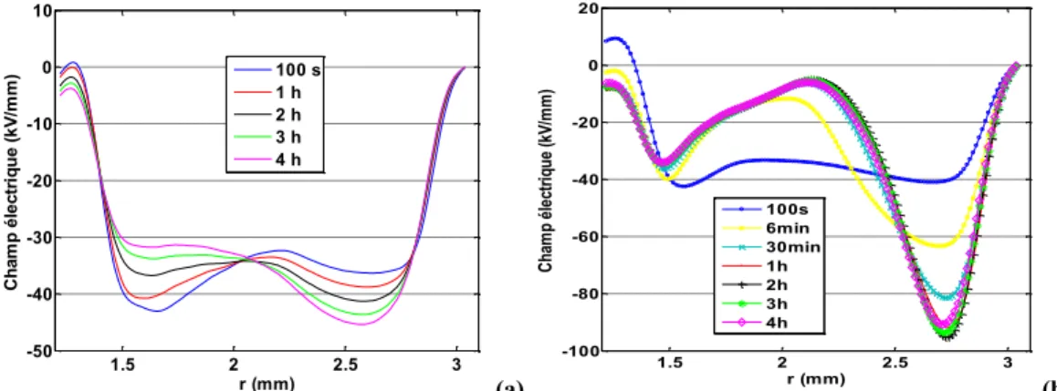
Crosslinking polyethylene using peroxide initiator leads to the formation of by-products, i.e. chemicals as acetophenone, cumyl-alcohol or alpha-methyl-styrene. These by products are known to favor the formation of space charges into the insulation, through processes not yet fully agreed: they can act as moieties capable of stabilizing charges, i.e. from an energy band diagram forming energy levels deep in the band gap [10], or forming ionized species that move into the insulation [8]. Fig. 2 illustrates the consequences of the presence of such by-products considering field distribution obtained on miniature cables by PEA method. These cables are representative structures of the full size cables, with semiconducting screens at both inner and outer interfaces of the insulation. Results obtained on an extensively degassed cable and on a poorly degassed one are compared. For the degassed cable, the field distribution moves as a function of charging time from a nearly capacitive shape (i.e. field larger near the inner semicon interface than near the outer) to a situation where the field is higher to the outer semicon. The maximum field remains in the range 40 to 45 kV/mm. In the case of the poorly degassed cable, the field is much higher as it reaches 100 kV/mm near the outer semicon. The features that are observed are clearly linked to the presence of by-products. The space charge density patterns plotted in Fig. 3 reveal that a huge amount of negative charges is formed adjacent to the outer screen whereas a positive space charge is formed close to the conductor. Such patterns correspond to heterocharge build-up, with as consequence the strengthening of the field next to the electrode.
175 1.5 2 2.5 3 -50 -40 -30 -20 -10 0 10 r (mm) C h am p é le ct riq u e ( kV /m m ) 100 s 1 h 2 h 3 h 4 h (a) 1.5 2 2.5 3 -100 -80 -60 -40 -20 0 20 r (mm) C ha m p él ec triq ue (k V/m m ) 100s 6min 30min 1h 2h 3h 4h (b) Fig. 2. Field distribution obtained in the insulation of miniature cable samples with 1.5mm thick
insulation. Measurements were achieved under a thermal gradient of 10°C, (Tin=60°C; Tout=70°C), under a voltage of -55kV applied to the conductor. (a) outgassed sample; (b) partly degassed sample.
(a) (b)
Fig. 3. Space charge density patterns corresponding to field profiles shown in Fig. 1. The color scale represents charge density in C/m3. (a) outgassed sample; (b) partly degassed sample.
The outgassing process (typically heating to 60°C for several days) applied on these model cables cannot be applied directly on full size cables for the energetic cost. Present researches are oriented to the processing of cables with keeping the beneficial aspects of crosslinking on thermomechanical properties withstanding of cables. We can mention here at least three lines of thought.
First, there is the development of crosslinking process that substantially reduces the amount of by-products. This is the incremental strategy in new generation of raw materials commercialized for HVDC cables [11], with still using peroxide crosslinking. A more innovating route is that based on the use of co-agents of crosslinking with allylic functions, in which virtually there is no by-products [12]. Very promising results in terms of space charge features were obtained in these materials, with behavior approaching that obtained on un-crosslinked material, i.e. low density polyethylene [13].
The second strategy consists in using nanocomposite polymers [14], with the advantage of keeping on thermoplastics. It has been shown in several instances that the incorporation of nanoparticles substantially reduces space charge accumulation in polymers [15]. As examples, nanometer-size fillers of silica (SiO2) [16] and magnesium oxide (MgO) [17] incorporated into
LDPE have been shown to be effective in suppressing space charge. The mechanisms behind those improvements are not completely clear at present [18], neither is the fate of the material integrity in time.
176 properties for being used as capacitors and its higher thermomechanical withstanding than polyethylene. New generation of mass impregnated cables have been recently proposed with PPLP [19] as a laminated paper consisting of Polypropylene (PP) film and conventional kraft paper. 3. MODELLING UNDER DC FIELDS: MACROSCOPIC APPROACH
It is well known that the capacitive field distribution within the radius of a cable under AC voltage follows a distribution of the form:
) ln( . o i ac AC r r r V r E (1)where ri and ro are the inner and outer radii of the cable. In case of DC stress, following
Maxwell's equation, here total current conservation, the electric field distribution in the cable insulation, in cylindrical geometry and under steady state condition is given by [2, 20]:
r r r E r E c c c where Ec and σc are the electric field and conductivity at the reference position rc. Eq. (1) and (2)
are equivalent only if σ is homogeneous. The conductivity gradient in a cable results from two processes. First, the field is non-homogeneous by geometry: a non-linear conductivity in field leads to a conductivity gradient. The second and main contribution is Joule effect due to the current circulating in the conductor. This leads to a thermal gradient across the insulation of the form:
r r W r T r T c o o 2ln where Wc is the heat produced and λ the thermal conductivity of the insulation.
The redistribution of the field goes with the formation of a space charge, whose density can be deduced based on the Poisson's equation. This geometrical space charge density is of the form:
dr
r r r E E div g ( . ) (4)where ε is the dielectric permittivity of the material. Considering Eq. 4, and supposing a negative voltage applied to the core of the cable, it follows that the field is negative (E=-gradV). As the last term is naturally negative, the expected space charge is negative. It is actually such feature that is measured under thermal gradient in Fig. 3 in case of degassed cable.
The above equations show that theoretically, the field distribution can be entirely determined if the dependence of conductivity vs. temperature and field is known. To provide experimental data on conductivity, we have carried out charging /discharging current measurements on cable samples. The active section was 250 mm long; 11 values of applied voltage ranging between 2 and 30 kV were applied under isothermal conditions with polarization/depolarization steps lasting for 1h/1h. Because of the cylindrical geometry of samples and of the inhomogeneity of the field, it is necessary to take a hypothesis on the mathematical form of the expression to solve the problem. We have supposed that conductivity is of the form below, as successively used for flat XLPE specimen [9]:
) ( ) ( ) ( sinh exp , r E r E T C T k E A T E B a 177 the following quantities were obtained: C = 2.15 x 10⁻⁷ m/V, A= 3.83 x 10⁴ S.V/m² and E
a =0.83 eV.
Fit curves for the current are shown in Fig. 4 along with computed field distribution as a function of time under stress and with consideration of polarity reversal on the cable. In this objective, the above equations have been solved in non-stationary stage using Finite Element Modelling.
2 10 40 10-13 10-12 10-11 10-10 10-9 10-8 10-7 C o n d u cti o n C u rr en t (A ) Voltage (kV) 30°C 40°C 50°C 60°C 70°C 80°C 90°C (a) 1.5 2.0 2.5 3.0 -15 -10 -5 0 5 10 15 -15kV-100s -15kV-600s -15kV-1800s -15kV-3600s -15kV-7200s 0V-300s 15kV-100s 15kV-600s 15kV-1800s 15kV-3600s 15kV-7200s E (kV/ mm) Radius (mm) (b) Fig. 4. (a) Fit model (solid line) and conduction current data (circle) obtained on miniature cables as
a function of temperature and field. (b) Field distribution profile in the cables with voltage inversion applied of ±15 kV and for thermal gradient of 10°C (Tin=60°C; Tout=70°C).
When thermal gradient is applied across the insulation, while current homogenization in the insulation takes place and space charges settle, the field value at the inner semicon decreases and increases at the outer semicon. This phenomenon of stress inversion is not very strong here as the conductivity is non-linear in field according to the results: in way it counterbalances the temperature effect on conductivity. The voltage polarity inversion does make the field distribution at the negative voltage step is broader than at the positive step, and field is higher at the inner semicon. Its magnitude difference is equal to the residual field after the polarization step shown in the figure. 4. CONCLUSION
The field distribution within the insulation of cables under thermal gradient and polarity inversion can be obtained through simulation based on conductivity characteristics from the measurement. Owing to the field grading nature of the material, the field distribution in isothermal conditions is homogenized in respect to the capacitive field distribution. The conductivity gradient under thermal gradient applied combined to the non-linearity in field leads to homogenization of the field in the insulation for voltage of 15 kV. At short time, there is field strengthening just after polarity inversion, representing possible aging route for the present case. Direct measurement of space charge on properly outgassed cables show that some trends can be properly anticipated by modelling; however heavy field distortion occurs with poor outgassing. This feature points to the need to confirm by measurement model outcomes.
REFERENCES
[1] G. Mazzanti, M. Marzinotto, Extruded Cables for High-Voltage Direct-Current Transmission, Wiley-IEEE Press, New Jersey, 2013
[2] D. Fabiani, G.C. Montanari, C. Laurent, G. Teyssedre, P.H.F. Morshuis, R. Bodega, L.A. Dissado,
HVDC cable design and space charge accumulation. Part 3: Effect of temperature gradient, IEEE Electr.
Insul. Mag., vol. 24_2, pp. 5-14, 2008
[3] S. Holé, T. Ditchi, J. Lewiner, Non-destructive methods for space charge distribution measurements:
what are the differences ?, IEEE Trans. Dielectr. Electr. Insul, vol. 10, pp. 670–677, 2003
178
Insul. Mag., vol. 24_3, pp. 26-37, 2008
[5] P. Notingher, S. Holé, L. Berquez, G. Teyssedre, An Insight into Space Charge Measurements, International J. Plasma Environmental Science & Technology, in press, 2016
[6] T. Maeno, H. Kushiba, T. Takada, C. M. Cooke, Pulsed Electro-acoustic Method for the Measurement
of Volume Charge in e-beam Irradiated PMMA, Proc. IEEE-CEIDP, pp. 389-397, 1985
[7] B. Vissouvanadin, T.T.N. Vu, L. Berquez, S. Le Roy, G. Teyssèdre, C. Laurent, Deconvolution
techniques for space charge recovery using pulsed electroacoustic method in coaxial geometry, IEEE Trans.
Dielectr. Electr. Insul., vol. 21, 821-828, 2014
[8] N. Hozumi, T. Takeda, H. Suzuki and T. Okamoto, Space Charge Behavior in XLPE Cable Insulation
under 0.2-1.2 MV/cm dc Fields, IEEE Trans. Dielectr. Electr. Insul., vol. 5, pp. 82-90, 1998
[9] T.T.N. Vu, G. Teyssedre, B. Vissouvanadin, S. Le Roy, C. Laurent, Correlating Conductivity and
Space Charge Measurements in Multi-dielectrics under Various Electrical and Thermal Stresses, IEEE Trans.
Dielectr. Electr. Insul., vol. 22, pp. 117-127, 2015
[10] M. Meunier, N. Quirke, A. Aslanides, Molecular modeling of electron traps in polymer insulators:
chemical defects and impurities, J. Chem. Phys, Vol. 115, pp. 2876-2881, 2001
[11] T. Hjertberg, V. Englund, P.O. Hagstrand, W. Loyens, U. Nilsson, A. Smedberg, Materials for HVDC
cables, Revue Electricité Electronique, N°4, pp. XI-XV, 2014.
[12] J.C. Gard, I. Denizet, M. Mammeri, Development of a XLPE insulating with low peroxide by-products, Proc. 9th Int'l Conf. Insulated Power Cables (Jicable), pp. 1-5, 2015
[13] T.T.N. Vu, G. Teyssedre, S. Le Roy, C. Laurent, Space Charge Criteria in the Assessment of Insulation
Materials for HVDC, IEEE Trans. Dielectr. Electr. Insul., submitted.
[14] T.A. Tùng, M. Fréchette, É. David, Điện môi nano : cấu trúc, tính chất, ứng dụng và xu hướng phát
triển, in this conference.
[15] T. Tanaka, T. Imai “Advances in nanodielectric materials over the past 50 years”, IEEE Electr. Insul. Mag., vol. 29_1, pp. 10-23, 2013
[16] X.Y. Huang, P.K. Jiang, Yi Yin, Nanoparticle surface modification induced space charge suppression
in linear low density polyethylene, Appl. Phys. Lett., vol. 95, p. 242905, 2009
[17] Y. Murakami, M. Nemoto, S. Okuzumi, S. Masuda, M. Nagao, N. Hozumi, Y. Sekiguchi, Y. Murata,
DC Conduction and Electrical Breakdown of MgO/LDPE Nanocomposite, IEEE Trans. Dielectr. Electr. Insul.,
vol. 15, pp. 33-39, 2008
[18] J.K. Nelson Nanodielectrics – the first decade and beyond, Proc. Intern'l Symp. Electrical Insulating Materials (ISEIM), (Niigata City, Japan), pp. 1-11, 2014
[19] G. Chen, M. Hao, Z.Q. Xu, A. Vaughan, J.Z. Cao, H.T. Wang, Review of high voltage direct current
cables, CSEE J. Power Energy Systems, vol. 1, pp. 9-21, 2015
[20] T.T.N. Vu, G. Teyssèdre, B. Vissouvanadin, S. Le Roy, C. Laurent, M. Mammeri, I. Denizet, Field
distribution in polymeric MV-HVDC model cable under temperature gradient : simulation and space charge measurements, Eur. J. Electr. Engg., vol. 17, pp.307-325, 2014