HAL Id: hal-01140836
https://hal.archives-ouvertes.fr/hal-01140836
Submitted on 9 Apr 2015HAL is a multi-disciplinary open access archive for the deposit and dissemination of sci-entific research documents, whether they are pub-lished or not. The documents may come from teaching and research institutions in France or abroad, or from public or private research centers.
L’archive ouverte pluridisciplinaire HAL, est destinée au dépôt et à la diffusion de documents scientifiques de niveau recherche, publiés ou non, émanant des établissements d’enseignement et de recherche français ou étrangers, des laboratoires publics ou privés.
Gas-liquid flow modeling in columns equipped with
structured packing
Cyprien Soulaine, Pierre Horgue, Jacques Franc, Michel Quintard
To cite this version:
Cyprien Soulaine, Pierre Horgue, Jacques Franc, Michel Quintard. Gas-liquid flow modeling in columns equipped with structured packing. AIChE Journal, Wiley, 2014, 60 (10), pp.3665-3674. �10.1002/aic.14550�. �hal-01140836�
To cite this
version : Soulaine, Cyprien and Horgue, Pierre and
Franc, Jacques and Quintard, Michel Gas-liquid flow modeling in
columns equipped with structured packing. (2014) AIChE Journal,
vol. 60 (n° 10). pp. 3665-3674. ISSN 0001-1541
O
pen
A
rchive
T
OULOUSE
A
rchive
O
uverte (
OATAO
)
OATAO is an open access repository that collects the work of Toulouse researchers and makes it freely available over the web where possible.
This is an author-deposited version published in : http://oatao.univ-toulouse.fr/ Eprints ID :
11896
To link to this article :
DOI: 10.1002/aic.14550
http://dx.doi.org/10.1002/aic.14550
Any correspondance concerning this service should be sent to the repository administrator: [email protected]
Gas-liquid flow modeling in columns equipped with structured
packing
Cyprien Soulaine ∗1, Pierre Horgue1, Jacques Franc1, and Michel Quintard 1,2 1Université de Toulouse ; INPT, UPS ; IMFT (Institut de Mécanique des Fluides de
Toulouse) ; Allée Camille Soula, F-31400 Toulouse, France
2CNRS ; IMFT ; F-31400 Toulouse, France
Abstract
This paper deals with the modeling of gas-liquid flow in distillation columns equipped with structured packing. The devices are seen as bi-structured porous media and a macro-scale model is proposed taking into account this specific geometry. In this model, the two liquid films, one-per-sheet, are treated separately and are allowed to exchange matter at the vicinity of the contact points between corrugated sheets. The model emphasizes mechanisms that lead to the liquid radial dispersion effects: a main part comes from the geometry itself, another part is due to the capillary effects. A particular attention is paid to model these phenomena from a macro-scale point of view. Finally, the simulation results are confronted to tomography imaging within a lab-scale column and show a qualitative good agreement of the liquid distribution.
Introduction
Structured packings play a large role in chemical engineering processes involving gas-liquid separa-tion such as air distillasepara-tion or CO2 absorption columns. They are made of an assembly of vertically
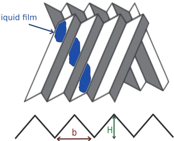
aligned corrugated sheets in which two adjacent sheets present symmetrical properties (i.e., ridges
and furrows are symmetrically inclined by a given angle from one sheet to another, see Figure 1). One of their main advantages lies in their ability to allow a large surface exchange between gas and liquid all the while offering low pressure drops, which made their success in the early 1990’s when they progressively outpaced the plate distillation columns industry. In fact, the pressure drop through structured packing is only one-fifth to one-tenth that of a trayed column.1
In order to design enhanced packings, it is of great importance to understand all the physical phenomena involved in the process and to be able to predict pressure loss, mass transfer efficiency and liquid spreading. Indeed, it is now well-established that a maldistribution of the liquid will heavily impact the efficiency of mixture separation.2 Spiegel and Meier3 and Olujic et al.4 have
provided a complete road map for improving the distillation processes over the next decades. One of the most important points they mentioned in their papers is the numerical modeling of gas-liquid flows. As a matter of fact, flow processes can be very complex and their modeling requires a large spectrum of knowledge in the fluid mechanics field. In a general way, the columns are operated in a counter-current flow mode: a thin gravity liquid film is sheared by the turbulent flow of a gas phase. All of these phenomena can be well captured by Computational Fluid Dynamic tools, which become more and more accurate and robust as they improve. For example, Sun et al.5 have recently
simulated a 3D two-phase flow within a representative elementary volume of a structured packing using a Volume-Of-Fluid (VOF) method. However, since a huge number of grid cells is required, these kinds of simulations are restricted to very small domains and cannot therefore be conceivably used for simulating flows within the entire columns representing the complete packing geometry.
To do so, the henceforth well-established strategy consists in a multi-scale approach such as the one proposed by Raynal and Royon-Lebeaud,6 in which structured packings are apprehended
as porous media with high porosity defining two scales of description: a small, pore-scale one and a macro-scale one assimilated to the packing scale. At the smaller scale, flows and other transfer phenomena are simulated using the exact geometry of the packing. Basically, to a cell of the mesh grid corresponds either a fluid or the solid structure and the two-phase flow can be computed using a VOF method involving gas turbulent modeling. On the other hand, at the macro-scale, the flow is governed by averaged equations. In this case, several continua are superimposed and a cell
of the grid contains both fluids and solids in the average sense. Information regarding the exact topology of the packing and the interfacial phenomena between the gas and the liquid or between the fluid and the solid structure are embedded in effective parameters such as permeability tensors and exchange coefficients, which can be evaluated by taking into account the periodicity of the pore-scale simulations.
In dry operating conditions, the flow at the larger scale is commonly modeled using a Darcy-Forchheimer law.7 The effective parameters that appear in this law, also called Ergun’s coefficients,8
are evaluated from either lab-scale and industrial-scale measurements which relate pressure drops to mass flow rates in the columns9–12 or using turbulent pore-scale simulations.13–21 Although this
modeling at the macro-scale of the turbulent single gas flow in columns equipped with structured packings provides good predictions, there is still no consensus regarding the macro-scale model that should be used for simulating gas-liquid flows in such devices. Indeed, due to this peculiar structured geometry, the two-phase flow modeling from a macroscopic point of view remains a challenging problem that is yet to be overcome. In particular, the macroscopic phenomena that lead to the spreading of a liquid point source at the top of a packing are still misunderstood, and the classical two-phase flow models in porous media, i.e. generalized Darcy’s laws, fail to properly capture the liquid distribution within the column. This latter discussion was made possible by improvements in tomography imaging,22–26 which provides a mapping of the liquid distribution within the packing
and is therefore an interesting tool for confronting simulation results with experimental ones. By analogy with two-phase flow modeling in a fixed-bed, macroscopic models have emerged. For instance, Iliuta et al.27 proposed a one-dimensional Eulerian two-fluid model with additional source
terms that represent the flow resistance due to the interaction of the fluids with the solid structure and the mutual friction between liquid and gas. Although the overall pressure loss and the liquid hold-up are in good agreement with the experimental results, this model does not reproduce the liquid radial spreading. To simulate this phenomenon, chemical engineering authors28–32 used what
they called a "dispersion" model which consists in an advection-diffusion equation solved in a vertical cylinder. Fourati et al.26 experimentally showed that the spread factor coefficient that appears in
in chemical engineering, they have no sufficient theoretical justifications. Some authors to model forces that lead to the mechanical dispersion by adding dispersive terms in tum equations. The origin of this additional term is confusing and can be interpreted ways: Lappalainen et al.33 assume that it comes from capillary pressure phenomena
et al.34 suggest that it is a higher order term, associated to the local convection
results from the upscaling procedure from the pore-scale to the larger scale.
the original macro-scale approaches developed to simulate this liquid radial dispersion columns, we can note the proposal of Aroonwilas et al.35, 36 more recently used by Sun et
modeling, the liquid distribution simulation relies on a discrete method. They consider the nodes represent the points of contact between two adjacent corrugated sheets. t, the authors assume that the liquid film can flow in four different directions (two per represent either a corrugated angle or an angle due to the gravity effects. Mass flow h direction are then evaluated using a probability law. Sun et al.5 evaluate this stream
VOF pore-scale simulations. The original work of Trifonov et al.37 is also based on
in mind that liquid flows in such devices with two preferential directions, Mahr and have found it convenient to split the liquid film into two separate phases flowing along t corrugated sheets. These phases are not (except perhaps at very low saturation) independent since adjacent sheets are in contact and the wetting liquid can flow from the other. This latter point is confirmed in the experimental study done by Alekseenko et al.40 who measured by fiber-optic sensors the thickness of the liquid film in the space confined
by two adjacent corrugated sheets. They have shown that, in the vicinity of the contact points between corrugated sheets, menisci form is at the origin of local liquid flow redistribution over the corrugated surfaces. Based on Mewes et al.’s early work41 who investigated anisotropic porous
structures, Mahr and Mewes38 have built a macroscale model from the integration over a control
volume of a pore-scale two-phase problem where the liquid flow was split in two distinct phases. Their resulting model is a three-phase Eulerian one, consisting of a gas phase and two liquid phases between which mass transfer processes occur. They forced the preferential direction of liquid films
due tosheet orientations by using anisotropic permeability tensors whose values differ for each liquid phase.
From our point of view, the idea of separating a liquid film into two fictitious phases that exchange matter at the vicinity of the contact points between corrugated sheets is a major break-throughin the modeling of the liquid distribution in the columns equipped with structured packings. This additional degree of freedom has a strong potential to catch the liquid radial spreading. In the present paper, we present an alternative model based on a similar idea. While Mahr and Mewes38
ha ve heuristically considered the mass transfer term as a difference of saturation between the two fictitiousphases, we introduce a different modeling that relies on a preliminary theoretical work done by Soulaine et al.42 In this work, authors qualified structured packings as bi-structured porous
me-dia and proposed macroscopic equations based on the volume averaging method43to simulate fully
saturated flows in such materials. They showed that the mass transfer between these two fictitious phases can be expressed as a difference between the two averaged pressure fields. We will discuss in the present study how this result can be extended to gas-liquid flow in structured packings.
The paper is organized as follows. In Section 2, we present the mathematical model developed to simulate gas-liquid flow in structured packings. A particular attention is paid to the treatment of mass exchange between liquid films. In Section 3, we present a simple model to evaluate multi-phase permeability tensors from an analogy with inclined plane. Section 4 deals with the numerical procedure used to solve this problem. Finally, in Section 5 we numerically solve the gas-liquid flow through a Mellapak 250.X and compare our results with tomography images obtained by Fourati et al.26
Mathematical model
The mathematical model introduced in this section is a heuristical extension to the case of gas-liquid flow of the two-pressure model proposed by Soulaine et al.,42 which simulates flows in fully
saturated bi-structured porous media. In the present model, a turbulent gas phase denoted γ is flowing at counter-current of a liquid phase. Following the old saying divide ut regnes, this latter phase is split into two separate gravity films denoted β1 and β2 respectively with the same physical
fluid properties (density ρβ, viscosity µβ, ...). Each film flows though the solid structure with two
different preferential directions, namely one direction per corrugated sheet. Moreover, they can exchange matter at the vicinity of contact points between two adjacent corrugated sheets. The set of macro-scale equations that makes up the model combines three continuity equations and three multi-phase Darcy’s laws and is directly based on the Darcy generalized model originally proposed by Muskat44 for two-phase immiscible flows in porous media.
When studying multi-phase flows in porous media, it is handy to introduce the notion of satura-tion Si. This variable corresponds to the filling rate of the pore-space by the i-phase. It is bounded
by 0 and 1, and the sum of all saturation fields satisfies the obvious relationship,
Sγ+ Sβ1+ Sβ2 = 1. (1)
The whole liquid volume fraction is simply Sβ = Sβ1+Sβ2. At packing-scale and assuming isothermal
and incompressible flows, with no mass transfer at the gas-liquid interface and no chemical reactions, the saturation profiles are governed by the following macro-scale mass balance equations,
ε∂Sγ ∂t + ∇.Uγ = 0, (2) ε∂Sβ1 ∂t + ∇.Uβ1 = ˙m, (3) ε∂Sβ2 ∂t + ∇.Uβ2 = − ˙m. (4)
In these equations, Ui stands for the superficial velocity vector of the i-phase, ε is the porosity of
the packing and ˙m models the amount of liquid in the β2-phase which is transferred to the β1-phase
at the corrugated sheets contact points. We will discuss further ahead the expression of this mass exchange term.
In the generalized Darcy’s model, the superficial velocity of each phase is estimated using a phase Darcy’s law, which means that the superficial velocities and the pressure gradients are related by
an apparent permeability tensor: Uγ = −Kγ µγ .(∇Pγ−ργg) , (5) Uβ1 = − Kβ1 µβ .(∇Pβ1−ρβg) , (6) Uβ2 = −Kβ2 µβ .(∇Pβ2−ρβg) . (7)
In these equations, µγ and µβ, ργ and ρβ are respectively the viscosity and the density of the gas
and liquid phases, g represents the gravity acceleration, Ki and Pi are the multi-phase permeability
tensors and the averaged pressure fields of the i-phase respectively. This modeling suggests that the pore space where the gas phase flows is reduced by the presence of the liquid phase near the solid packing structure, and vice versa. Consequently, the multi-phase permeability tensors strongly depend on the liquid saturation profiles. Moreover, to account for inertia and turbulence effects, these tensors can also depend on the velocity of each phase.7, 8, 45 This point will be discussed in
the next section.
The present momentum equations could be complexified to account for the viscous coupling due to the gas-liquid shear-stress46, 47and the coupling effects between the two fictitious liquid films.39, 42
This effect can be of importance near the flooding point when hydrodynamics is mostly determined by the shear stresses on the gas/liquid interface. However, as observed in the numerical results of the last section, these simplifications emphasize the roles played by the packing geometry and by the situation in the vicinity of the contact points between corrugated sheets to explain the macroscopic phenomena that lead to the spreading of a liquid point source on top of a packing. In our model, as shown in the next section, Kβ1 and Kβ2 are tensors with non-zero off-diagonal coefficients. Both
have different values that express different preferential directions due to the inclined angle of a corrugated sheet. If the shear stress effect participates to the liquid radial dispersion, it is not at leading order.
Besides this main liquid spreading effect due to the packing geometry, one can notice in Eqs (2)-(4) that at the opposite of most models proposed in the literature to simulate flows in gas-liquid contactors,27, 39, 41, 48 we do not assume that the averaged pressure field in the liquid phases is equal
to the gas one. This results in an additional dispersion effect, as pointed out by Lappalainen et al.,33
caused by the capillary effects. Actually, these phenomena are well-known by multi-phase porous media investigators who introduce a macro-scale capillary pressure pc defined as the difference
between both gas and liquid averaged pressure fields and function, at least, of saturation,49–51
pc(Sβ) = Pγ−Pβ. (8)
Wettability effects are generally included in the relative permeability and capillary pressure relationships for the generalized Darcy’s law model, which is based on a quasi-static view of the interface locations. In the case for structured packings, this latter assumption is not necessarily acceptable, and it is possible that modifications of the equation structure itself would be necessary. In general, this is still an open question. In the case of structured packings with film flows, i.e., low liquid saturation, we may have various situations. In cryogenic conditions, wettability is stronger and we believe that the potential dewetting of the solid surface is small, while this is probably likely to occur more rapidly for hydrocarbon compounds, for example. In this paper, we will skip that potential difficulty for the time being.
Since our model involves two liquid phases, we can, without any assumptions, introduce the following regional capillary pressures,
pci(Sβ1, Sβ2) = Pγ−Pβi with i = 1, 2, (9)
and since by definition of the intrinsic averages, Pβ = Sβ1
Sβ1+Sβ2Pβ1 +
Sβ2
Sβ1+Sβ2Pβ2 we may write the
trivial relation, pc(Sβ1 + Sβ2) = Sβ1 Sβ1 + Sβ2 pc1(Sβ1, Sβ2) + Sβ2 Sβ1 + Sβ2 pc2(Sβ1, Sβ2). (10)
Actually, at the macro-scale, the capillary pressure translates the local curvilinear gas-liquid in-terface dynamic. The effect of capillary dispersion is therefore consistent with Alekseenko et al.40
experiments that showed the presence of a meniscus at the sheet’s contact points. They also showed
that, at this very spot, the liquid is redistributed over the corrugated surface. This means that some amount of liquid can be transferred from one sheet to its adjacent one, and inversely. In our model, this quantity is described by ˙m. When a fluid is split in two separate fictitious phases for up-scaling purposes, Soulaine et al.42 demonstrated that, for the one-phase flow case, the mass exchange rate
is evaluated in terms of an averaged pressure fields difference
˙ m = h
µβ
(Pβ1−Pβ2) , (11)
where h is a mass exchange coefficient. We adopt such a formulation for the multiphase flow case since it ensures that the sign of ˙m will always follow the liquid stream-wise, something which is not granted by a mass exchange expressed as a linear function of the difference in both liquid volume fractions as proposed by Mahr and Mewes.39 Indeed, one may imagine geometries where
the pressure difference and the saturation difference have opposite signs. Finally, introducing Eq (8) into Eq (11), the mass exchange equation reads
˙ m = h
µβ
(pc2(Sβ1, Sβ2) − pc1(Sβ1, Sβ2)) , (12)
and is therefore directly linked to the capillary effects in the vicinity of the contact points between corrugated sheets.
Flow characterization at large scale
The mathematical model introduced in the previous section involves several effective parameters as the multi-phase permeability tensors that relates the superficial velocities to the pressure gradients, or the mass exchange coefficient between the two fictitious liquid films. These parameters embed information related to both the packing geometry and flow configuration (gas-liquid and liquid-liquid interfaces). Therefore, they directly depend on the pore-scale physics and they can be evaluated from pore-scale simulations over a representative elementary volume of the packing. If this multi-scale analysis is now well-established for the evaluation of the gas permeability tensor,13–21the prediction
of Kβ1 and Kβ2 from local simulations is more complicated since it requires the knowledge of the
exact location of the gas-liquid interface. However, according to some assumptions, this local two-phase flow problem can be highly simplified and has some helpful analytical solutions.
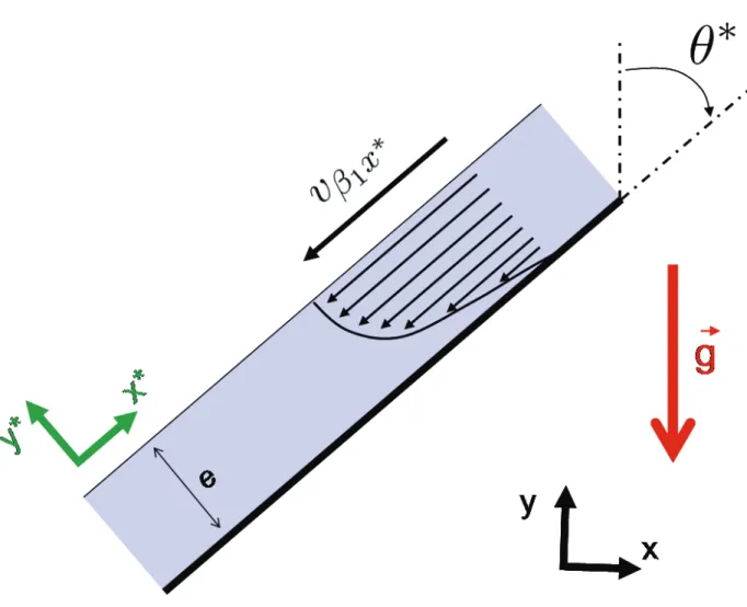
Considering a corrugated sheet inclined by an angle θ from the vertical axis, a liquid film will flow downward according to an effective corrugation angle θ∗ that varies between the corrugation
angle θ and the gravity vector orientation. In order to characterize the liquid film, it is then common to consider the flow over a plane inclined by θ∗ (see Figure 2). Actually, θ∗ is an effective parameter
that includes the 3D features of the corrugations. It may be evaluated from an analytical formula (see the proposal in Shilkin et al.52 as an example) or from a pore-scale simulation of films flowing
over the corrugated surface. Moreover, most of the industrial packings are made of perforated metal sheets. These perforations lead to deviations of the liquid stream-wise and therefore impact the value of θ∗. The dependency of θ∗ to the sheet holes could be caught by film simulations over
the real topology of the pierced corrugated surface.
Besides this geometrical conceptualization, further simplifications are made regarding the two-phase flow motion itself. First, we assume a free surface liquid film and neglect shear stress effects at the gas-liquid boundary. Then, we neglect inertial effects, which means that the film’s thickness is constant along the inclined plane. With such a configuration, the liquid flow is governed by a simple analytical solution53 in the coordinate system related to the inclined plane. The averaging
of this solution leads to a linear relationship between the superficial velocity and the gradient of the averaged pressure field. Actually, this relationship looks like a multi-phase Darcy’s law with a relative permeability that depends on the β1-liquid saturation. With simple linear algebra, this
relation can be expressed in the coordinate system related to the packing, we have
Kβ1 = K0 2 S 3 β1 sin2 (θ∗) cos(θ∗) sin(θ∗) 0
cos(θ∗) sin(θ∗) cos2(θ∗) 0
0 0 0 . (13)
from the solution of a liquid film over a plane inclined by −θ∗ we get, Kβ2 = K0 2 S 3 β2 sin2 (θ∗) −cos(θ∗) sin(θ∗) 0
−cos(θ∗) sin(θ∗) cos2(θ∗) 0
0 0 0 . (14)
In these two multi-phase permeability tensors, K0 represents the permeability value if two adjacent
corrugated sheets were put together with θ = 0◦. We can notice the presence of off-diagonal terms
in the xOy plane of the sheet. Moreover, all the zero values in the z direction mean that there is no liquid flow in this direction. In fact, some amount of liquid can flow in this direction by crossing the sheet perforations, but this effect is probably very small. The permeability tensors of the packing rotated by 90◦ are merely obtained by switching the coefficients of subscript x with
the ones of subscript z. In Eqs (13)-(14), we recognize a relative permeability in terms of the liquid saturation flowing over each corrugated surface to the power of three (S3
βi). This relative
permeability, reminiscent of the proposal of Brooks and Corey,50 is intrinsic to the assumption
leading to the laminar free surface flow over an inclined plane. A deeper investigation of the saturation dependency could be performed from pore-scale simulations on a more realistic topology of the corrugated sheet.23, 54–56 This could also provides some information regarding the effect of
inertia and enlighten a potential dependency to the averaged liquid film velocity.
Concerning the vapor permeability tensor, the coefficients could be obtained from dry gas turbu-lent pore-scale simulations over a representative elementary volume of the packing or from lab-scale measurements (see the review in the section of this paper). In the spirit of a Forchheimer’s law,7the
permeability tensor should depend on the Reynolds number to account for the inertia and turbu-lence effects. The resulting tensor is weighted by a relative permeability to account for the reduction of the pore space where the gas flows, due to the presence of the liquid films at the sheet walls. In the absence of accurate two-phase flow simulations over the real structure and to remain consistent with the liquid permeability tensors, we postulate a Brook and Corey weighting function.50 Finally,
we have Kγ= K0 1 + αReγ S3 γ sin2 (θ) 0 0 0 cos2 (θ) 0 0 0 0 , (15)
where α is a model parameter that denotes the inertia/turbulence effects in the gas phase.
The mathematical model we have introduced in the previous section involves two capillary pressures, pc1 and pc2, that should satisfy the relation Eq (10). Actually, without deeper theoretical
investigations, we have no further informations regarding the saturation dependency of pci. To
simplify the problem, we postulate, in agreement with Eq (10), that,
pci(Sβ1, Sβ2) = pc(Sβi) with i = 1, 2. (16)
The problem is therefore reduced to the evaluation of the capillary pressure pc that could be
measured experimentally using classical methods. Here, we are going to use the well-known Brook and Corey correlation:50
pc(Sβi) = pc0(Sβi) 1
λ (17)
where pc0 is the entry capillary pressure and λ is the pore-size distribution index. This coefficient
has a small value for heterogeneous pore size distribution and a large value when the pore size distribution is regular. We will fix its value at λ = 2.57 Hence, only p
c0remains a model parameter.
The exchange coefficient h is the latest effective parameter that appears in our model. It quantifies the amount of liquid that flows from a sheet to its closest neighbor at a sheet contact point. Stricto sensu, it should depend on the saturation profiles and on the liquid Reynolds number if the film flow involves inertia effects. In the absence of accurate pore-scale simulations, we will consider that h is only weighted by the liquid saturation,
h = (Sβ1+ Sβ2)h
∗, (18)
this saturation dependency.
Numerical implementation
In this section, we focus on the implementation of the mathematical problem introduced in Section 2. We chose to code it using the finite volume CFD library OpenFOAM®.58, 59 From a numerical
point of view, this problem can be seen as a three-phase flow problem in which a gas phase and two liquid phases are flowing through an anisotropic porous medium. Since the sum of the 3 saturations is equal to unity and since the liquid pressures can be related to merely the gas pressure from the capillary pressure concept, the problem can be reduced to the resolution of a gas pressure (Pγ)
and two liquid saturation fields (Sβ1 and Sβ2). The numerical treatment of this kind of problem,
well-known by the petroleum industry, has received a lot of attention in the literature and several books offer comprehensive reviews of the resolution methods available.60, 61 Among the different
methods available, we retained the IMPES algorithm (IMplicit Pressure, Explicit Saturation).62
The main idea of this widely used method is to solve the pressure and saturation equations in a segregated manner, this choice being compatible with the OpenFOAM® algorithmic structure. At
each time step, the pressure equation is solved implicitly whereas the saturation equations are solved explicitly. This method has the multiple advantages of being quite simple to implement and requiring less computer memory compared with other methods such as a simultaneous solution method or the Euler-Euler models with porous source terms. Moreover, as it will be further discussed, an efficient time-step management leads to stable and very fast computations. The 3-phase solver is developed on an existing two-phase IMPES solver impesFoam that has been developed in a previous work.63
The following paragraphs introduce the main parts of the numerical model solving multi-phase flows in structured packings.
The first step of the IMPES method consists in the prediction of the gas pressure field within the computational domain. This stage requires a partial differential equation that governs P ≡ Pγ.
To form this latter, the three velocities are expressed as
Uγ= −Mγ.∇P + Lγ.g, (19)
Uβ1 = −Mβ1.∇P + Lβ1.g+ Mβ1.∇Pc1, (20)
Uβ2 = −Mβ2.∇P + Lβ2.g+ Mβ2.∇Pc2, (21)
where Mi represents the mobility tensor of the i-phase, and the tensor Li, which has a time
dimen-sion, deals with the contribution of gravitational effects. It must be noted that more complex models involving viscous resistance terms between phases for example could be written using this generic formulation. Therefore, that same solver could be used for further, and possibly more complex, investigations of this problem.
Defining the total velocity U as the sum of the phase-velocities, we have
U= −M.∇P + L.g + Mβ1.∇Pc1+ Mβ2.∇Pc2, (22) where M =X i Mi and L = X i Li with i = γ, β1, β2, (23)
since the sum of the continuity equations Eqs (2) to (4) give a divergence-free velocity (∇.U = 0), we can therefore formulate the following pressure equation:
∇.(−M.∇P ) + ∇. (L.g + Mβ
1.∇Pc1+ Mβ2.∇Pc2) = 0. (24)
This equation is solved implicitly using the Mi and L tensors and the capillary pressures computed
with the latest values of the liquid saturation profiles (Sn−1β
i ). The velocity fields are then deduced
from Eqs (19)-(21) using the new computed gas pressure field Pn. Then, the liquid mass balance
equations Eq (3) and Eq (4) are solved explicitly one after the other. Finally, the gas saturation can be merely deduced using the values of Sn
β1 and S
n
β2 from Eq (1). At the end of this stage, the
multi-phase permeability tensors and the capillary pressures are updated with the new values of the saturation profiles.
Because of the hyperbolic feature of these conservation laws and the strong non-linearities thats exists in the model (relative permeabilities and capillary pressure correlations), solving this set of equations can lead to high instabilities. To ensure stability of the numerical simulations, the flux terms have been discretized with a first order upwind scheme.
Because of their explicit treatment, the computation of both saturation equations requires small time steps limited by a CFL condition. On the contrary, the implicit treatment of the pressure equation is time-consuming. To significantly reduce the CPU time, we embrace the smart time-step management method proposed by Chen et al.64 who noticed that the pressure field relaxation was
much longer than the evolution of the saturation. Hence, in their method, the pressure equation is no longer solved at each time step. It results in a very stable and fast algorithm that could allow the use of this solver in an industrial background.
Results and discussion
Now that we have introduced the conceptual, mathematical and numerical basis of our gas-liquid flow model in structured packing, we are going to compare the simulation results with the liquid distribution experimentally obtained by Fourati et al.26 In their experiment, they have mapped
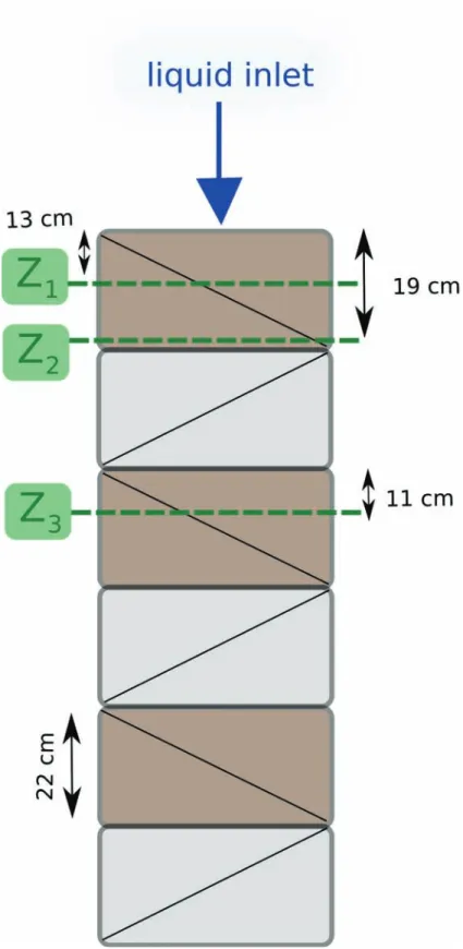
liquid distribution by means of gamma-ray tomography at different positions downstream a source point injection. Their column was 40 cm in diameter and 1.5 m in height and was filled with six 22 cm high layers of structured packings Mellapak 250.X manufactured by Sulzer Chemtech (see Figure 3). The packing geometry is characterized by a large porosity ε ≈ 0.98 and an inclination angle of the flow channels with the vertical direction of θ ≈ 30°. The packing elements were alternatively rotated around the axis of the column by 90° relative to each other. The column was operated in the counter-current flow mode and was fed at the top by a liquid (water) point source (the inlet was approximatively a 50 mm circular section). As for the gas (air), it was injected at the bottom of the column. Local liquid hold-up profiles were mapped for several cross-sections (Z1, Z2 and Z3
in Figure 3).
We have tried to reproduce these experimental results with the model we have developed. How-ever, all the exact protocol of Fourati et al.26 has not been respected and we have adopted some
assumptions. First, we do not consider gas injection in the column to focus on the radial liquid dispersion only. This is consistent with the conclusions of Fourati et al.26 who have operated the
gas-liquid flow at counter-current for a wide range of mass flow rates, and found that the radial dispersion coefficient does not vary significantly with the flow conditions. Hence, this assumption seems suitable at leading order. In addition, we have supposed that the corrugated sheets were not perforated. In fact, these perforations should modify the value of θ∗ and the inclined plane analogy
is no longer true. From the Mellapak 250.X geometrical features and using the formula proposed by Shilkin and Kenig,65 we obtain that θ∗ ≈20°. According to our definition, K0 is the permeability
of the packing if two adjacent sheets were assembled with corrugations aligned with the vertical axis. Hence, using a hydraulic radius this permeability can be approximated by K0=
R2 h
8 = H2b2
4H2+b2
where H = 1.2 cm and b = 2.4 cm are the dimensions of the corrugation (see Figure 1). We obtain K0≈10−5m2. Since we do not account for gas turbulence in these simulations, α ≡ 0. Our model
requires additional informations, especially those regarding the capillary pressure coefficients pc0
and h∗ in the mass exchange function ( ˙m). An adjustment from experiments or pore-scale
sim-ulations is beyond the scope of this paper. Instead, we have performed a sensitivity analysis to these parameters and compared the results with the saturation profiles in the cross-section Z2 that
belongs to the first pack. Therefore, we have simulated the flow in the first layer for different values of pc0 and h∗. The computational domain is a cylinder whose height is 22 cm and the diameter is
40 cm, meshed with 72000 hexaedrea (see Figure 4).
The liquid injection is carried out at the center of the highest cross-section as depicted in Figure 4 with Uβ1 = Uβ2 = 0.015 m/s. The physical properties of air and water in the simulation are
respectively ργ = 1.17 kg/m3, µγ = 1.85 × 10⁻⁵kg/m/s and ρβ = 998 kg/m3, µβ = 10−3kg/m/s.
Once the steady-state is reached, in the order of a few seconds, we have qualitatively compared the liquid distribution at the cross-section Z2. In this plane, located at the bottom of the pack,
Fourati et al.26 have shown that the liquid hold-up, initially circular, has spread in the direction
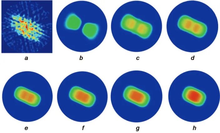
of the corrugated sheets and that the liquid saturation was more important at the center of the cross-section (see Figure 5a). We have tried different sets of values for pc0 and h∗. In the absence
vicinity of the contact points, it is very difficult to decide which set of values is the most realistic. Nevertheless, this sensitive analysis helps to understand how the model behaves according to the weight of the liquid mass exchange function. In Figure 5 we have plotted the simulation results we obtained for pc0 = 0.1 kg/m/s2 and h∗ varying in the range 0 to 10. For h∗ = 0 (see Figure
5b), one notices two separate liquid distributions. In this case, there is no liquid transfer from one sheet to another ( ˙m = 0) and a film remains on the same sheet during all the process. For larger values up to h∗ = 3 (see Figure 5c,d,e), the simulation results are in keeping with the experimental
hold-up mapping. However, there are two peaks on both sides of the packing center which does not appear in Figure 5a. The value h∗ = 4 is in better agreement with the tomography results and is
the one we will chose for the following simulations. For the highest values of the mass exchange coefficient, the radial liquid spreading is very weak, and the saturation pattern at the bottom of the packing is similar to the injection one. In this case, i.e, for h∗ high enough we are in a situation
of local equilibrium and we recover the dynamic of the classical two-phase flow in porous media model. This sensitivity analysis illustrates that, besides the role played by the structured packing geometry, the radial dispersion phenomenon is also governed by capillary effects at the vicinity of the contact points between two adjacent corrugated sheets.
Once the coefficients related to the liquid mass exchange are determined, we have simulated the flow within the three first packing layers. The first and the third layers are characterized by the permeability tensors Kβ1, Kβ2 and Kγ defined by Eqs (13), (14) and (15). For the second pack
which is rotated around the axis of the column by 90° relative to the former layer, its permeability tensors are merely obtained switching the coefficients with index x by those indexed z in these equations. In this work, we simulate the gas-liquid flow in the column one structured packing at a time. An alternative solution could be to simulate the gas-liquid flow within the whole column by defining two different porous media with different permeability tensors according to their rotation angle around the vertical axis. The first method combines the advantages to reduce CPU time and to directly use the solver as detailed in the previous section. Once the steady-state is reached in the first pack, we get the outlet boundary values of the velocity fields and apply them at the inlet of the next pack following,
Un+1 β1 .ninlet = U n+1 β2 .ninlet = Un β1.noutlet+ U n β2.noutlet 2 , (25) where Un+1β 1 .ninlet and U n+1
β2 .ninlet are the liquid velocity boundary values at the inlet of a pack
while Un
β1.noutlet and Unβ2.noutlet denote the boundary values at the outlet of the previous pack. This
relation means that there is no additional redistribution of the liquid flow rate across the section at packing elements junctions. Actually, an accumulation of liquid in this zone due to capillary effects that generates a liquid film attached to the extremities of the packing metal sheets has been experimentally reported.66–68 The liquid saturation at junctions between packing units is twice
more important than in the interior of the packing unit. If this phenomena should create additional pressure drop, Fourati et al.26 have experimentally shown that it does not strongly participate
to liquid redistribution. The hereby model does not account for this accumulation phenomena. However, it could be easily enhanced in this direction considering an additional porous medium layer with different physical properties in between two successive packs. An alternative model would introduce a specific boundary condition instead of Eq (25). Such a condition for the split model discussed in this paper has not been developed yet and is beyond the scope of this paper.
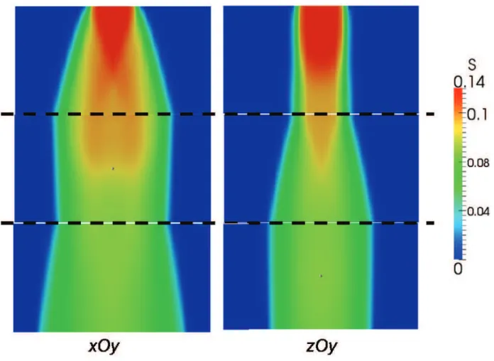
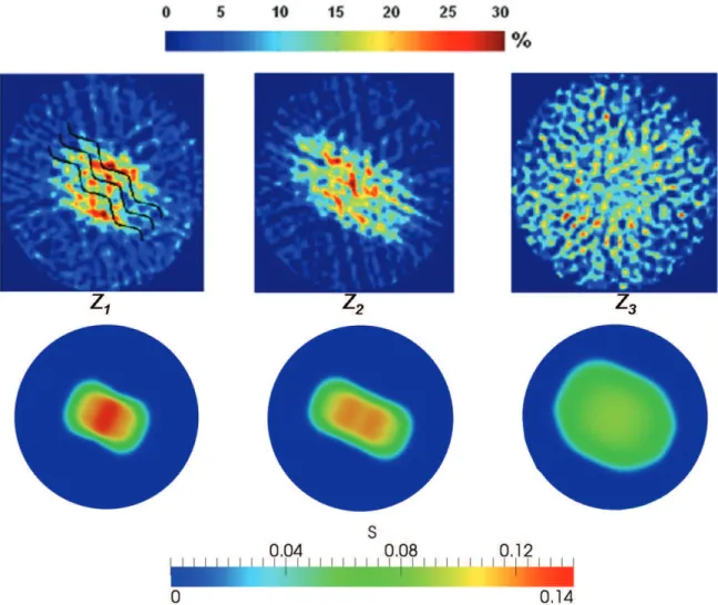
The liquid saturation profile is plotted in Figure 6 according to a slice in the xOy plane (on the left) and another in the zOy plane (on the right), the y axis being the vertical axis, xOy corresponding to the orientation of the corrugated sheet of the first and third packing elements and, as a matter of fact, zOy those of the second pack. We notice that the liquid only spreads according to the x direction within the first and the third packs while the radial dispersion only occurs into the z direction in the second packing unit. In Figure 7, we have compared the simulation results with the liquid hold-up maps in the cross-section of the column obtained by tomography imaging.26
Simulations are qualitatively comparable to the experimental results: as expected we get a liquid spreading following a preferential direction (x or z according to the structured packing orientation) that leads to a liquid distribution almost homogeneous after several packing transitions. However, the order of magnitude of the liquid saturation is twice lower than the experimental values and we can notice that, in the third pack (Figure 7, Z3 plane), the liquid spreading is not as diffusive
the effective corrugation angle estimation we use does not account for the sheet perforations. A more accurate value of θ∗could be obtained from pore-scale simulations of the liquid film flow over a
realistic topology of the corrugated sheets. Furthermore, strong assumptions (laminar flow, constant film thickness...) have been made to derive the simple liquid film model we used to evaluate the multiphase permeability tensors. Indeed, regarding this latter point, Raynal et al.15 have shown
that the liquid thickness evaluated from the Nusselt analytical solution may be underestimated up to twice the expected value, even more. Third, the coefficients of the transfer function ( ˙m) have been approximatively adjusted and further investigations deserve to be carried out. Finally, as it has already been mentioned, the condition we used at the junction between two successive packing elements is a simplified view of the reality.
Conclusion
We have developed a mathematical model based on a multi-scale analysis to simulate gas-liquid flow through distillation columns equipped with structured packing. In this modeling, the packing is seen as a bi-structured porous medium considering each group of oriented sheets as a separate structure. The two liquid films, one-per-sheet, are then seen as two overlapping continua where the interaction between each other is modeled through a transfer function.
This modeling allows one to understand the mechanisms that lead to the liquid spreading. A major part of this spreading is directly induced by the criss-crossing structured geometry of the packing that forces the liquid films to flow following two different preferential directions. Combined to these geometric features, the capillary effects play an important role since they govern the transfer of some amount of liquid from a corrugated sheet to another sheet at the vicinity of the contact points. The simulations performed with this model have been successfully compared to laboratory-scale measurements. In particular, the model can properly catch the liquid distribution within the column.
However, the numerical results are mainly qualitative and show the model potential. Indeed, the effective properties like relative permeabilities, the effective corrugation angle and the capillary pres-sures have been evaluated from simple analytical solutions. Further investigations regarding their
saturation-dependency from either accurate pore-scale simulations or experimental measurements could make the model becomes quantitative as well.
Acknowledgments
We gratefully acknowledge Manel Fourati, Ludovic Raynal and Véronique Roïg who provided us their tomography imaging results before their publication and also for their fruitful discussions about structured packing. We also thank Farah Houdroge who helped to improve the English of this manuscript.
Literature Cited
1. Agrawal R, Herron DM. Air liquefaction: Distillation in Encyclopedia of Separation Science:1895 - 1910Academic Press 2000.
2. Pavlenko A, Zhukov V, Pecherkin N, et al. Investigation of flow parameters and efficiency of mixture separation on a structured packing AIChE Journal. 2014;60:690–705.
3. Spiegel L, Meier W. Distillation Columns with Structured Packings in the Next Decade Chemical Engineering Research and Design. 2003;81:39-47.
4. Olujic Z, Jödecke M, Shilkin A, Schuch G, Kaibel B. Equipment improvement trends in distil-lation Chemical Engineering and Processing: Process Intensification. 2009;48:1089-1104.
5. Sun B, He L, Liu BT, Gu F, Liu CJ. A new multi-scale model based on CFD and macroscopic calculation for corrugated structured packing column AIChE Journal. 2013;59:3119-3130.
6. Raynal L, Royon-Lebeaud A. A multi-scale approach for CFD calculations of gas-liquid flow within large size column equipped with structured packing Chemical Engineering Science. 2007;62:7196 - 7204.
7. Forchheimer P. Wasserbewegung durch Boden Z. Ver. Deutsch. Ing.. 1901;45:1782-1788.
9. Bravo JL, Rocha JA, Fair JR. Pressure drop in structured packings Hydrocarbon processing. 1986;65:45-49.
10. Stichlmair J, Bravo JL, Fair JR. General model for prediction of pressure drop and capacity of countercurrent gas/liquid packed columns Gas Separation & Purification. 1989;3:19-28.
11. Rocha JA, Bravo JL, Fair JR. Distillation columns containing structured packings: a compre-hensive model for their performance. 1. Hydraulic models Industrial & Engineering Chemistry Research. 1993;32:641-651.
12. Billet R, Schultes M. Prediction of Mass Transfer Columns with Dumped and Arranged Pack-ings: Updated Summary of the Calculation Method of Billet and Schultes Chemical Engineering Research and Design. 1999;77:498 - 504.
13. Hodson JS, Fletcher JP, Porter KE. Fluid mechanical studies of structured distillation packings I Chem E. Distillation and Absorption. 1997;2:999-1007.
14. Petre CF, Larachi F, Iliuta I, Grandjean BPA. Pressure drop through structured packings: Breakdown into the contributing mechanisms by CFD modeling Chemical Engineering Science. 2003;58:163 - 177.
15. Raynal L, Boyer C, Ballaguet JP. Liquid Holdup and Pressure Drop Determination in Structured Packing with CFD Simulations The Canadian Journal of Chemical Engineering. 2004;82:871-879.
16. Khosravi Nikou MR, Ehsani MR. Turbulence models application on CFD simulation of hydro-dynamics, heat and mass transfer in a structured packing International Communications in Heat and Mass Transfer. 2008;35:1211 - 1219.
17. Said W, Nemer M, Clodic D. Modeling of dry pressure drop for fully developed gas flow in structured packing using CFD simulations Chemical Engineering Science. 2011;66:2107 - 2117.
18. Rafati Saleh A, Hosseini SH, Shojaee S, Ahmadi G. CFD Studies of Pressure Drop and Increas-ing Capacity in MellapakPlus 752.Y Structured PackIncreas-ing Chemical EngineerIncreas-ing & Technology. 2011;34:1402-1412.
19. Hosseini SH, Shojaee S, Ahmadi G, Zivdar M. Computational fluid dynamics studies of dry and wet pressure drops in structured packings Journal of Industrial and Engineering Chemistry. 2012;18:1465–1473.
20. Owens SA, Perkins MR, Eldridge RB, Schulz KW, Ketcham RA. Computational Fluid Dynamics Simulation of Structured Packing Industrial & Engineering Chemistry Research. 2013;52:2032-2045.
21. Soulaine C, Quintard M. On the use of a Darcy-Forchheimer like model for a macro-scale de-scription of turbulence in porous media and its application to structured packings International Journal of Heat and Mass Transfer. 2014;74:88–100.
22. Roy S, Kemoun A, Al-Dahhan MH, Dudukovic MP, Skourlis TB, Dautzenberg FM. Counter-current flow distribution in structured packing via computed tomography Chemical Engineering and Processing. 2004;44:59 - 69.
23. Raynal L, Ballaguet JP, Barrère-Tricca C. Determination of mass transfer characteristics of co-current two-phase flow within structured packing Chemical Engineering Science. 2004;59:5395-5402.
24. Sidi-Boumedine R, Raynal L. Influence of the viscosity on the liquid hold-up in trickle-bed reactors with structured packings Catalysis Today. 2005;105:673 - 679.
25. Viva A, Aferka S, Toye D, Marchot P, Crine M, Brunazzi E. Determination of liquid hold-up and flow distribution inside modular catalytic structured packings Chemical Engineering Research and Design. 2011;89:1414–1426.
26. Fourati M, Roïg V, Raynal L. Experimental study of liquid spreading in structured packings Chemical Engineering Science. 2012;80:1 - 15.
27. Iliuta I, Petre CF, Larachi F. Hydrodynamic continuum model for two-phase flow structured-packing-containing columns Chemical Engineering Science. 2004;59:879 - 888.
28. Cihla Z, Schmidt O. A study of the flow of liquid when freely trickling over the packing in a cylindrical tower Collec. Czechosl. Chem. Commun.. 1958;23:569-577.
29. Porter KE, Jones MC. A theoretical prediction of liquid distribution in a packed column with wall effect Trans. Instn Chem. Engrs. 1963;41.
30. Bemer GG, Zuiderweg FJ. Radial liquid spread and maldistribution in packed columns under different wetting conditions Chem. Eng. Sci.. 1978;33:1637-1643.
31. Hoek PJ, Wesselingh JP, Zuiderweg FJ. Small scale and large scale liquid maldistribution in packed columns Chem. Eng. Res. Des.. 1986;64:431-449.
32. Edwards DP, Krishnamurthy KR, Potthoff RW. Development of an Improved Method to Quan-tify Maldistribution and Its Effect on Structured Packing Column Performance Chemical En-gineering Research and Design. 1999;77:656-662.
33. Lappalainen K, Manninen M, Alopaeus V. CFD modeling of radial spreading of flow in trickle-bed reactors due to mechanical and capillary dispersion Chemical Engineering Science. 2009;64:207 - 218.
34. Fourati M, Roïg V, Raynal L. Liquid dispersion in packed columns: Experiments and numerical modeling Chemical Engineering Science. 2013:266–278.
35. Aroonwilas A, Tontiwachwuthikul P. Mechanistic model for prediction of structured packing mass transfer performance in CO2 absorption with chemical reactions Chemical Engineering Science. 2000;55:3651 - 3663.
36. Aroonwilas A, Chakma A, Tontiwachwuthikul P, Veawab A. Mathematical modelling of mass-transfer and hydrodynamics in CO2 absorbers packed with structured packings Chemical En-gineering Science. 2003;58:4037 - 4053.
37. Trifonov Y, Sunder S, Houghton P. Modeling of mixture separation in column with structured packing. Effect of liquid maldistribution. Distillation and Absorption 2006, IChemE Symposium. 2006:764–772.
38. Mahr B, Mewes D. CFD Modelling and Calculation of Dynamic Two-Phase Flow in Columns Equipped with Structured Packing Chemical Engineering Research and Design. 2007;85:1112 - 1122.
39. Mahr B, Mewes D. Two-phase flow in structured packings: Modeling and calculation on a macroscopic scale AIChE Journal. 2008;54:614-626.
40. Alekseenko SV, Markovich DM, Evseev AR, Bobylev AV, Tarasov BV, Karsten VM. Experimen-tal investigation of liquid distribution over structured packing AIChE Journal. 2008;54:1424-1430.
41. Mewes D, Loser T, Millies M. Modelling of two-phase flow in packings and monoliths Chemical Engineering Science. 1999;54:4729 - 4747.
42. Soulaine C, Davit Y, Quintard M. A two-pressure model for slightly compressible single phase flow in bi-structured porous media Chemical Engineering Science. 2013;96:55 - 70.
43. Whitaker S. The Method of Volume Averaging;13 of Theory And Applications of Transport in Porous Media. Kluwer Academic Publishers 1999.
44. Muskat M. Physical principles of oil production. McGraw-Hill, New York. 1949.
45. Soulaine C. Modélisation des écoulements dans les garnissages structurés : de l’échelle du pore à l’échelle de la colonne. PhD thesisInstitut National Polytechnique de Toulouse 2012.
46. Raats PAC, Klute A. Transport in Soils: The Balance of Momentum Soil Science Society of America Journal. 1968;32:452-456.
47. Baveye P, Sposito G. The Operational Significance of the Continuum Hypothesis in the Theory of Water Movement Through Soils and Aquifers Water Resources Research. 1984;20:521-530.
48. Attou A, Boyer C, Ferschneider G. Modelling of the hydrodynamics of the cocurrent gas-liquid trickle flow through a trickle-bed reactor Chemical Engineering Science. 1999;54:785 - 802.
49. Leverett MC. Capillary Behavior in Porous Solids Transactions of the AIME. 1940;142:152-169.
50. Brooks RH, Corey AT. Hydraulic properties of porous media Hydrology Papers. 1964;3.
51. van Genuchten MT. A Closed-form Equation for Predicting the Hydraulic Conductivity of Unsaturated Soils Soil Sci. Soc. Am. J.. 1980;44:892–898.
52. Shilkin A, Kenig EY. A new approach to fluid separation modelling in the columns equipped with structured packings Chemical Engineering Journal. 2005;110:87 - 100.
53. Nusselt W. Die Oberflachenkondensation des Wasserdampfes Ver. Deut. Ingr.. 1916;60.
54. Szulczewska B, Zbicinski I, Górak A. Liquid Flow on Structured Packing: CFD Simulation and Experimental Study Chemical Engineering & Technology. 2003;26:580-584.
55. Valluri P, Matar OK, Hewitt GF, Mendes MA. Thin film flow over structured packings at moderate Reynolds numbers Chemical Engineering Science. 2005;60:1965 - 1975.
56. Haroun Y, Raynal L, Legendre D. Mass transfer and liquid hold-up determination in structured packing by CFD Chemical Engineering Science. 2012;75:342 - 348.
57. Corey AT. The interrelation Between Gas and Oil Relative Permeabilities Producers Monthly. 1954:38-41.
58. Jasak H. Error Analysis and Estimation for the Finite Volume Method with Applications to Fluid Flows. PhD thesisDepartment of Mechanical Engineering Imperial College of Science, Technology and Medicine 1996.
59. Weller HG, Tabor G, Jasak H, Fureby C. A tensorial approach to computational continuum mechanics using object-oriented techniques Computers in Physics. 1998;12:620-631.
61. Chen Z, Huan G, Ma Y. Computational Methods for Multiphase Flows in Porous Media. Society for Industrial and Applied Mathematics 2006.
62. Sheldon JW, Zondek B, Cardwell WT. One-dimensional, incompressible, non-capillary, two-phase fluid flow in a porous medium T. SPE AIME. 1959;216:290–296.
63. Horgue P, Soulaine C, Franc J, Guibert R, Debenest G. An open-source toolbox for multiphase flow in porous media (submitted to) Computer Physics Communications. 2014.
64. Chen Z, Huan G, Li B. An Improved IMPES Method for Two-Phase Flow in Porous Media Transport in Porous Media. 2004;54:361-376.
65. Shilkin A, Kenig EY. Fluid separation modelling in the columns equipped with structured packings using the hydrodynamic analogy in European Symposium on Computer-Aided Process Engineering-15, 38th European Symposium of the Working Party on Computer Aided Process Engineering;20 of Computer Aided Chemical Engineering:331 - 336Elsevier 2005.
66. Suess P, Spiegel L. Hold-up of Mellapak structured packings Chem. Eng. Process. 1992;31:119–124.
67. Toye D, Crine M, Marchot P. Imaging of liquid distribution in reactive distillation packings with a new high-energy x-ray tomography Meas. Sci. Technol.. 2005;16:2213–2220.
68. Alix P, Raynal L. Liquid distribution and liquid hold-up in modern high capacity packings Chem. Eng. Res. Des.. 2008;86:585–591.
List of Figures
1 Schematic of two adjacent sheets. A liquid film flows over each corrugated surface according to a preferential direction. . . 28 2 Laminar liquid film flow along a plane inclined by the gravity angle. The velocity
profile may be described by the Nusselt’s analytical solution. . . 29 3 Column used by Fourati et al. (2012) to investigate liquid hold-up by tomography
imaging. Scheme of the column filled with six layers of structured packings rotated around the axis of the column by 90° relative to each other. Liquid and gas are respectively injected at the top and at the bottom of the column. Liquid saturation profiles are recorded by tomography imaging at the cross-sections Z1, Z2 and Z3. . . 30
4 Geometry and mesh of a packing element. It consists in a cylinder (40 cm in diameter, 22 cm in height) meshed with 72000 hexaedrea. For the first pack of column, the liquid injection is performed at the center of the highest section (red section) . . . 31 5 Liquid distribution in the first pack (cross-section Z2) for several values of h∗ and
pc0= 0.1 kg/m/s2. (a) Experimental results by;26(b) h∗= 0; (c) h∗= 1; (d) h∗= 2;
(e) h∗ = 3; (f ) h∗= 4; (g) h∗ = 5; (h) h∗= 10. For the lowest values of h∗ (0 to 3),
one notes two peaks of liquid saturation on both sides of the section center but these peaks do not appear on (a). Values of h∗between 4 and 5 are in better agreement
with the experimental results. For higher values, the model tends to local equilibrium. 32 6 Liquid distribution within the three first packing elements of the column displayed
according to the xOy plane (on the left) and to the zOy plane (on the right). We notice an alternative liquid spreading in the x direction (first and third layers) and in the z direction (second layer). . . 33 7 Comparison between the liquid hold-up mapping obtained by tomography (top26)
b
H
liquid lm
Figure 1: Schematic of two adjacent sheets. A liquid film flows over each corrugated surface accord-ing to a preferential direction.
Figure 2: Laminar liquid film flow along a plane inclined by the gravity angle. The velocity profile may be described by the Nusselt’s analytical solution.
Figure 3: Column used by Fourati et al. (2012) to investigate liquid hold-up by tomography imaging. Scheme of the column filled with six layers of structured packings rotated around the axis of the column by 90° relative to each other. Liquid and gas are respectively injected at the top and at the bottom of the column. Liquid saturation profiles are recorded by tomography imaging at the cross-sections Z1, Z2 and Z3.
Figure 4: Geometry and mesh of a packing element. It consists in a cylinder (40 cm in diameter, 22 cm in height) meshed with 72000 hexaedrea. For the first pack of column, the liquid injection is performed at the center of the highest section (red section)
Figure 5: Liquid distribution in the first pack (cross-section Z2) for several values of h∗ and pc0=
0.1 kg/m/s2. (a) Experimental results by;26 (b) h∗ = 0; (c) h∗ = 1; (d) h∗ = 2; (e) h∗ = 3; (f )
h∗ = 4; (g) h∗ = 5; (h) h∗ = 10. For the lowest values of h∗ (0 to 3), one notes two peaks of
liquid saturation on both sides of the section center but these peaks do not appear on (a). Values of h∗between 4 and 5 are in better agreement with the experimental results. For higher values, the
Figure 6: Liquid distribution within the three first packing elements of the column displayed ac-cording to the xOy plane (on the left) and to the zOy plane (on the right). We notice an alternative liquid spreading in the x direction (first and third layers) and in the z direction (second layer).
Figure 7: Comparison between the liquid hold-up mapping obtained by tomography (top26) and by