Working Paper No. 297
The Condor Programmer's Manual - Version II
July, 1987
Sundar Narasimhan
David M. Siegel
Abstract: - This is the CONDOR programmer's manual, that describes the hardware and
software that form the basis of the real-time computational architecture built originally for
the Utah-MIT hand. The architecture has been used successfully to control the hand and
the MIT-Serial Link Direct Drive Arm in the past. A number of such systems are being
built to address the computational needs of other robotics research efforts in and around
the lab. This manual, which is intended primarily for programmers/users of the CONDOR
system, represents our effort at documenting the system so that it can be a generally useful
research tool.
A.I.Lab Working Papers are produced for internal circulation and may contain information that is, for example, too preliminary or too detailed for formal publication. It is not intended that they should be considered papers to which reference can be made in the
1 Overview and History 2 Introduction
2.1 The Hand Project ... 3 Hardware
3.1 Design Considerations ... 3.2 Components ...
3.3 The VME-Bus system ...
3.3.1 The Ironics IV-3201 Single Board Computer ... 3.3.2 VM E-Bus ... 3.3.3 3.3.4 3.3.5 3.3.6 3.3.7 3.3.8 3.3.9 Interrupts . ...
Ironics IV-3273 system controller . HVE Bus to Bus adaptor ... Memory Board on the VME . . . . A/D and D/A converter boards.. The Arm Controller Hardware . The Motorola parallel-port board . 4 Software
4.1 Introduction and Motivation . . . . . 4.2 Roadmap ...
4.3 Level Zero software for the CONDOR 4.3.1 A primer on interaction . ...
4.3.2 Memory management routines 4.3.3 Math routines...
4.3.4 The I/O Package ... 4.3.5 Strings Library ... 4.3.6 Data Transfer routines ... 4.3.7 Simple Real Time Tasking ... 4.3.8
4.3.9 4.3.10
HVE Libarary - The memory m Dealing with multiple processor Command Parser Library - Inpt
... ... o.... ... ... ... ... ... o... ... ... ... apped connection... . . . . t routines . . . . .
Contents
3 34.3.11.1 4.3.11.2 4.3.11.3 4.3.12 Hash Tal 4.3.13 Buffer ro 4.3.14 Tree libre 4.3.15 Small set 4.3.16 Miscellan 4.3.17 Internals 4.3.17.1 4.3.17.2 4.3.17.3 4.4 Level One Softw
4.4.1 Message 4.4.1.1 4.4.1.2 4.4.2 The Sun 4.4.2.1 4.4.2.2 4.4.2.3 4.4.2.4 4.5 Support for Rea
4.5.1 MOS - A 4.6 Debugging Supp 4.6..1 4.6..2 4.6..3 4.6.1 Local Dii 4.6.2 Conclusic 4.7 Acknowledgemel 4.8 References ... 5 Programs 5.1 CONF ... 5.2 DL68 ... 5.3 ICC . . . . 5.4 BURN68.... 5.5 RAW... 5.6 MRAW . . . . 5.7 CONDOR. . . 5.8 XPLOT ....
The command parser and X Windows ... Parsing for arguments in the command parser . Window Geometry . ... bles . . . .. . . . . utines . . . . ary . .. . . . ... . . .... . . . .. package ... .... eous routines...
Interrupts and Vectors . . . . The interrupt generator . ...
The interrupt handler . ...
'are for the CONDOR . . . . Passing Support . ...
Introduction ... M essages ...
end . . . . EVH Handler - Mailbox handler on the Sun end How the EVH handler works ... . . How to use the EVH handler ... . . List of functions used for message passing . . . . l Time tasks ... ..
Minimal Operating System . . . . ort...
Commands added to GDB . . . . Ptrace, Wait, and friends ... . . . . How to use the debugger . ...
erences ...
nts . . . . . . ..
1
A Device Drivers 96
A.1 Configuration parameters ... ... 96
A.2 The devsw structure and the devtab table. ... ... . . 97
A.3 Explanation of the internals ... 99
A.3.1 Init routine ... 99
A.3.2 Open routine ... 101
A.3.3 Close routine ... 103
A.3.4 Other standard routines ... 104
A.3.5 Support for non-standard routines . ... 105
B Hardware configuration 107 B.1 The Ironics boards ... 107
The Utah-MIT Hand project was started in the fall of 1983 to build a high performance dexterous robotic end-effector, capable of human-like performance. The hand itself was built by the fall of 1985. The first version of the hand was controlled by an earlier incar-nation of the hardware and software presented in this document. (This earlier version was based on Motorola 68000 single-board computers on the Intel Multibus. This version will be referred to as CONDOR -Version I in this document.)
A redesign of the actuators was completed in the fall of 1986. Coupled with this was a redesign of the computational architecture, both hardware and software. It is this second version (known as CONDOR -Version II) that this document describes.
Although the computational architecture was developed originally to control the Utah-MIT hand, the architecture that has resulted is a powerful, multi-micro-processor system that is fairly general in its scope, and is oriented specifically towards real-time computation. The architecture has been used to control other robotic devices besides the Utah-MIT hand, notably the MIT serial link direct-drive ARM. There are a number of these systems in the process of being built at MIT to address the real time needs of other research groups at MIT's Artificial Intelligence Laboratory. Besides this, a number of research efforts around the nation (in particular Stanford's NYMPH architecture and a research architecture being built at IBM) have acknowledged our system's influence on their design.
Introduction
2.1 The Hand Project
The Utah-MIT hand is a pneumatically powered four-fingered hand, built to investigate
issues related to machine dexterity, as part of an ongoing project at the University of Utah's
Center for Engineering Design and M.I.T's Artificial Intelligence Laboratory. Each finger
of the hand has four joints. Each joint is driven by a pair of pneumatic actuators operating
at around 70 psi. The actuator used is an extremely fast, single stage, pressure servo
controlling the position of a graphite piston encased in a glass cylinder. The movement
of a piston is transmitted to the actual joint by tendons routed over pulleys. The hand
is approximately anthropomorphic in size and shape. A more detailed discussion of the
design issues involved can be found in Jacobsen et al. [1985, 1986].
The hand has thus sixteen degrees of freedom in itself (four fingers each with four degrees
of freedom) (see Fig. 2.1). It also has two wrist degrees of freedom to some extent, but
these are not presently actuated. The hand is mounted physically on the arm subsystem,
which comprises of four cartesian degrees of freedom. The hand can be moved up and down
in a vertical direction (the z axis), and horizontally, (the y axis) using this arm. In addition
to these two degrees of freedom, a two degree of freedom z-y table is positioned beneath the
arm bringing the total degrees of freedom of the wrist relative to a fixed absolute reference
frame to four. The actuator assembly (known as the actuator pack) is mounted separately
from the arm subassembly. The tendons from the actuator pack are routed to the hand
via a mechanism known as the remotizer which is essentially a mechanism for mounting
the hand separately from the actuator pack while keeping constant the lengths of all the
tendons even while the hand is moving.
The manual is organised into the following sections.
1. A section on hardware. This section describes briefly, the different components that
comprise the hardware configuration of the CONDOR system.
2. System and application level software support needed for the CONDOR system. Since
this manual is a programmer's manual, we provide explanations at two levels; one
aimed mainly at a user of the system, and another for a prospective maintainer or
implementor of system software. Some sections intended for the latter group assume
a fairly detailed knowledge of Unix and the C programming language.
Users whose main interest in the computational architecture is to use it to control
the hand ought to read Section 4.3. This section documents the external interface
that the software presents to the application programmer and provides a description
of all the utility libraries.
Figure 2.1: The Utah-MIT dexterous hand
3. Manual pages for the various programs that go into making up the development and
run-time environment that is the CONDOR system.
The version of the system described in this document pertains mostly to the development
environment that runs on the Sun-3 workstations in the Lab.
1, and the runtime environment
that runs on Motorola 68020 based single board computers on the VME-Bus.
Hardware
This section discusses the hardware architecture of the CONDOR hand control system. The purpose of this section is to provide the motivation for some of the design decisions that were made during the development of the CONDOR system, and to provide some guidance for installing and maintaining such a system.
3.1 Design Considerations
An early decision was made to use off-the-shelf hardware whenever possible. This de-cision was motivated by the observation that computations needed to control a general purpose robotic hand are suitable for general purpose computer architectures, and custom-made computer hardware is rarely cost effective when only few systems are to be built. In addition, keeping a custom built system at the state of the art requires constant im-provements in the hardware, and is a never ending proposition. Such a task is best left to commercial companies that specialize at this.
An initial examination of the types of computations that were expected to be performed indicated that a multiprocessor based hardware solution would work well. Using multiple processors is advantageous for several reasons. Most importantly, additional computer power can be obtained by adding more processors to the system. In addition, alternate control strategies can be tested simply by partitioning them in different ways. For example, reprogramming a uniprocessor that controls multiple robots would require much more work, since many time critical events need to be serviced in a complex fashion.
Once the decision to use multi-micro-processors had been made, the individual processor on which the system would be based had to be chosen. Table. 3.1 compares the price to performance ratio of some of the CPU's available then that were considered. (See also Table. 3.2 which gives benchmark timings for some of the operations on the current configuration).
Table 3.1: Comparisons of processing power available from different hardware configura-tions.
Processor Type Speed Cost Comments
Microvax II 1 MIP mod interconnect problems Vax 11/750 1 MIP high interconnect problems Symbolics 3600 1 MIPS high lacks real time support National 32032 1 MIPS low
Motorola 68000 1 MIPS low lacks floating point Motorola 68020 2.5 MIPS low
In some robotics controllers, the enormous attention paid to efficiency and performance has often resulted in cryptic, unmaintainable and inextensible systems. Since our system is to be used primarily as a research tool, it was desirable that it be highly flexible, ex-tensible and portable to other hardware architectures as well. However, at the same time, performance goals had to be met. These goals were often conflicting, but we felt that by appropriately organizing the computational hierarchy we would be able to strike the right balance between them. For a more detailed discussion of the pertinent issues involved see Siegel et al., [1985] and Narasimhan et al., [1986].
The important features of the CONDOR hardware that are expected to persist across multiple system configurations are therefore (see Table. 3.3):
1. Powerful multi-micro-processor system. (the individual CPU that the system is based on may change although at present we strongly rely on the Motorola 680xx line).
2. Standard interconnect scheme. The present version of the system (i.e. CONDOR -Version II), is based on the industry standard VME-bus. An earlier version was based on the Intel Multibus. These high-speed busses form the basis for our inter-processor communication scheme. Using an industry-standard bus to form the backplane of our system has the added advantage in that peripherals like A-D/D-A boards, and digital I/O boards are readily available for such busses as are powerful single-board computers.
3. Tightly-coupled multi-processor interconnect. The present version of the sys-tem and quite a few in the future will be based on the shared dual-port memory paradigm for interprocessor communication. Although support may be added for network interfaces, parallel ports etc., these are not expected to be fast enough to satisfy our real-time constraints which are typical of high-performance robotic con-trollers.
3.2 Components
The hardware architecture of the CONDOR system consists of the following components (see Fig. 3.1);
1. The analog controller subsystem. This subsystem can be used to bring up the hand in a turn-key mode which is extremely useful in running certain diagnostic tests and quick demonstrations. It requires very little else to operate and is described in the document The Utah-MIT dexterous hand - Electronics, and will not be described further in this document. Users of the CONDOR will rarely use the system in this mode. This system essentially consists of the box with flashing lights next to the hand. The more important function played by this box is that it houses and powers the analog drivers needed to power the hand's electronics. This forms the lowest level of the hand control system.
§3.2 Components
2. The CONDOR processors. In addition to the analog controller at the lowest level, a bunch of four MOTOROLA 68020 processors are used to control the hand when it is running under digital control. These are housed in a VME-Bus cardcage. The analog-to-digital and digital-to-analog boards, are presently housed on the Multibus, but they will be moved to the VME-bus shortly. The processor boards are plugged into the VME-Bus across which data is transferred for interprocessor communication. A-D/D-A transfers occur across the VME-Bus to Multibus adaptor.
3. The Sun-3. The CONDOR microprocessors are interfaced to a Sun-3 via a bus-to-bus adaptor link. The adaptor basically extends the bus on the development machine to include the bus on which the control processors reside. In addition to this extremely fast connection that can transfer data at rates comparable to a standard VME-Bus, there also exists a slower connection between the Sun and the microprocessor subsys-tem via a 9600 baud serial line. The Sun is used mainly for program development. The user interface for most control programs also presently resides on this machine. 4. The Arm control hardware. The Arm subsystem is controlled by Slo syn stepper motors which are controlled by a controller card that also plugs into the Multibus.
In this document, we do not discuss either the arm control hardware or the analog controller hardware designed for the Utah-MIT hand. Our emphasis will primarily be on the Motorola 68020 system designed to run control software and the development software that presently runs on the Sun.
M68020 M68020 M68020 M68020
II
I
VME-BUS
Figure
3.1:
Hardware block diarram for the Utah-MIT hand controller.
Fifur 3 1: Hardware..oc.. . . . e... ... ... ...ntrolle3.3 The VME-Bus system
3.3.1 The Ironics IV-3201 Single Board Computer
This processor board forms the main workhorse of the multi-micro-processor controller hardware. The Ironics IV-3201 Processor board is a powerful single-board computer based on the Motorola 68020 microprocessor, coupled with the fast 68881 floating-point unit. In addition to the microprocessor, many other functions are provided on-board as described below.
An industry-standard 28-pin byte-wide memory socket is provided to hold a PROM which contains up to 32 Kbytes. This prom is used to provide the monitor which bootstraps user programs.
The board contains one megabyte of RAM, which may be expanded to a total of four megabytes if desired. This no wait-state, dead-lock protected RAM is dual-ported; i.e it may be accessed either locally by the processor, or as a VME-Bus Slave by another device. Memory base addresses may be jumpered to start at any of a set of predefined locations. It is necessary that the dual port address of every board in a system be configured correctly for the software to operate correctly (see Appendix B, for this configuration information). The Ironics single board computer is adequately described in the document titled
IV-3201 68020 CPU Board - User's Guide, which is available from Ironics, Inc. Please refer to this document for further information regarding the features it has, and for board-specific
configuration information. 3.3.2 VME-Bus
The individual ironics cpu boards are all plugged into the industry standard VME-Bus backplane. More documentation on the VME-Bus can be found in the document titled The VME-Bus specification manual which is available from a number of manufacturers. This document is also known as the IEC 821 Bus and the IEEE P1014/D1.0.
The VME-bus specification provides for a variety of options. The version of the back-plane we use in our system is based on the J1-J2 two-high connectors each of which are 96 pins.
The bus specification includes provisions for data transfer, interrupts and bus arbitra-tion. It specifies a bus that has 32 bits of address and data and 5 bits (or 32 values) for address modifier codes. This enables address cycles on the bus to be further distinguishable by the code that is passed on the modifier lines, and obviates the need for specialized i/o spaces.
The VME-Bus'es different address spaces are mapped into separate blocks of the full 32 bit address space on the Ironics 3201 processor board. Please see the document titled IV-3201 68020 CPU Board available from Ironics, for the particular mapping that is currently available from them.
The VME-Bus provides for 4 different levels of bus requests and grants. We have chosen to put all the Ironics cpu boards at bus request level 3 (BR3). The synergist-3 type of bus-to-bus adaptor is configured to run at level 2 (BR2) while the hve-2000 type of adaptor is configured to run at level 3 (BR3).
§3.3 The VME-Bus system
Please see the section below, for information pertaining to VME-Bus interrupts. The bus arbitration on the VME-Bus we presently rely on the system controller func-tions performed by the IV-3273 system controller available from Ironics. We do not use the system controller available on the HVE bus to bus adaptor which must be disabled on the slave VME-Bus, for proper operation on the CONDOR system.
3.3.3 Interrupts
The VME-Bus supports vectored interrupts. The basic idea is that an interrupting device raises an appropriate interrupt request line to indicate that it wishes to interrupt a processor. The VME-Bus supports eight levels of interrupt priority. The device that wishes to service the interrupt is known as the interrupt handler. When this device senses that a peripheral wants to interrupt the processor, it acknowledges the interrupt, starting an IA CK cycle. The peripheral is supposed to place a vector number on the data bus when it receives the interrupt acknowledge signal. The vector number indicates to the processor the routine that it must execute in response to the requested interrupt. For a detailed explanation of the signal transitions during this entire process, see the VMEBus Specification Manual. For an explanation of how processor vectors work, see the Motorola
68020 User's Manual. Please see Section 4.3.17.1 for programming information regarding
interrupt vectors.
Each of the Ironics 3201 boards has an interrupt handler chip that can be programmed to respond to any of the eight VME-Bus interrupt levels, or any of eight local onboard interrupt sources. Please refer to the Ironies 8301 User's Manual and the Motorola 68155 Interrupt Handler -Data sheets for further information on this interrupt handler chip.
3.3.4 Ironics IV-3273 system controller
The Ironics IV-3273 system controller board performs the important function of arbi-trating bus requests on the slave VME-Bus. This board also has a number of devices like a serial io device, a parallel port device etc., on it, that can be used by the 3201 proces-sor boards. For further information on this controller board, please refer to The Ironies
IV-3273 System Controller - User's Guide available from Ironics.
This board's serial io chip (the Motorola M68681) forms the terminal driver of our system. Please see Page 23 for programming details concerning hardware devices, and Appendix A for details on how to write a device driver for a new device that is to be incorporated into the system. This serial driver is needed only for initial bootstrapping and debugging operations. Since the serial chip on the ironics system controller card can be controlled only by one processor at a time, forcing all processors' terminal i/o through this single serial chip is hopelessly cumbersome. To overcome this problem we have designed a pseudo terminal emulator which the processors can use to communicate with the Sun over the bus-to-bus adaptor. This psedo terminal emulator or pty is designed as a service to work on top of the message passing system which will be described later.
3.3.5 HVE Bus to Bus adaptor
The Hal Versa Engineering board connects the slave VME-Bus on which the Ironics single board computers are mounted to the VME-Bus that houses the Sun-3. Physically this subsystem consists of two boards connected together by two cables. While one board is plugged into the Sun-VME backplane the other is designed to plug into the slave VME system.
There are two versions of the hve adaptor that are currently in use. The first version, called the synergist-3 is a 16-bit device while the second called the hve-2000 is a full-fledged 32 bit device that connects up the two vme-busses in a completely transparent fashion.
The synergist-3 version of the adaptor provides i/o locations that the users can write to on either side of the bus. These i/o locations when written to, cause dynamic connection or disconnection of the bus-to-bus adaptor. For the CONDOR software system to function correctly, these i/o locations must be configured correctly. (Please see Section B for details). For programming details on how to use the bus-to-bus adaptor system from the Sun please see Section 4.3.8. For programming details on how to use the mailbox communication mechanism to communicate to the Sun from the microprocessors see Section 4.4.1.1.
The bus-to-bus adaptor in addition to providing a fast and transparent memory-to-memory link also provides a way of mapping interrupts from the Ironics processors to the Sun CPU. To accomplish this purpose we have left ONE interrupt level (level one) connected between the two busses. The other interrupt levels are disconnected to prevent unwanted interaction between the Sun's Operating system and interrupting devices on the slave vme bus. The sun initiates communication with the ironics processors by using the mailbox interrupt present on the processor boards while the ironics processors use this single interrupt level to interrupt the sun across the bus-to-bus adaptor in order to communicate with it.
3.3.6 Memory Board on the VME
The message passing system requires each processor to have a section of memory devoted primarily for message passing. While it is easy to get such memory on the CONDOR processors, getting such memory from the Sun end may not be such an easy task. Rather than use Sun's DVMA space or other solutions that were not very appealing, we chose to augment the slave VME-Bus with an extra 1Megabyte memory board intended solely for use by the Sun.
Any commercially available memory board will do the task. We recommend the MVME-204 board made by Motorola. This board is available in two flavors - the MVME-204-1 is a one megabyte board, while the MVME-204-2 is a 2 megabyte memory board.
If adding such a board would not be possible owing to other constraints, the software can be reconfigured and recompiled so that a small portion of memory from an Ironics processor board can be used by the sun for this purpose.
§3.3 The VME-Bus system
3.3.7 A/D and D/A converter boards
A variety of analog-to-digital and digital-to-analog converter boards are available off-the-shelf for the VMEBus. In this section we describe the boards made by Data Translation, that are the ones currently being used by the CONDOR controller for its data acquisition operations. (Users intending to use the system present in MIT's AI Laboratory should refer to Section 4.6.1).
There are a number of features that one ought to watch out for in picking data acquisi-tion hardware. Primary consideraacquisi-tions are speed, number of channels and number of bits of resolution provided by the board. Other factors that merit evaluation are programmable gain, interrupt capability and protection circuitry.
1. Data Translation A/D Boards: The A/D board that we recommend for the CON-DOR system is a device that has 32 single ended channels each at 12-bits of resolution. The board is made by Data Translation and its product number is DT-1401. It has a programmable gain option and provides interrupting capability. For programming details on data acquisition hardware see Section 4.3.6.
2. Data Translation D/A Boards: The DT1406 D/A board made by Data Translation complements the A/D board effectively. It provides 8, 12 bit channels, intended for voltage output. Besides multiplying DAC's the board also has a DC/DC converter for noise reduction.
3.3.8 The Arm Controller Hardware
The arm controller hardware is based on the Magnon stepper-motor controller on the Multibus. Since this is also a feature peculiar to our local environment, documentation on this is deferred to a later section. Programmers interested in using this system should refer to Section 4.6.1 for details.
3.3.9 The Motorola parallel-port board
In our system the capability for parallel i/o is provided by the Motorola MVME-340 parallel port board. This board is based on the Motorola 68230 Programmable parallel port and Timer chip.
The versatility of this chip, and consequently that of the board makes it impossible to describe it adequately in this document. For further documentation on the chip and the board please see the document titled MVME-840 - User's manual available from Motorola.
Table 3.2: Timing Information (in microseconds)
Explanation Add Sub Multiply Divide Fadd Fsub Fmul Fdiv Motorola 68000 5.2 6.0 8.2 57.0 170.1 190.0 275.7 642.2 68020/no cache 6.2 5.6 6.3 41.0 32.4 32.4 40.8 42.3 68020/cache 4.0 2.9 4.0 26.7 24.7 24.8 31.5 35.0
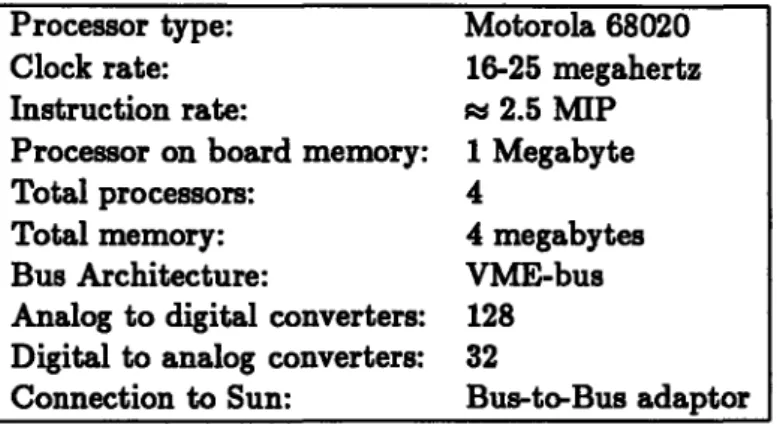
Table 3.3: Computational components of the hand controller. Processor type: Motorola 68020
Clock rate: 16-25 megahertz
Instruction rate: r 2.5 MIP
Processor on board memory: 1 Megabyte
Total processors: 4
Total memory: 4 megabytes
Bus Architecture: VME-bus
Analog to digital converters: 128 Digital to analog converters: 32
Software
This section will describe the software that has been developed for the CONDOR system. The version of the software described here runs on the MOTOROLA 68020 version of the system. Future ports to other architectures will adhere to the protocols described herein to a very large extent.
This section is intended primarily for other programmers of the CONDOR system for control applications; It presumes prior knowledge of the "C" Programming Language I and of the 4.2 BSD Unix environment; The subsections have been organized roughly in increasing order of detail and complexity.
4.1 Introduction and Motivation
The software system was designed to achieve the following goals:
(a) Provide a flexible environment to aid the development of real-time control programs. (b) Provide efficient, low-overhead support for commonly performed operations.
(c) Provide an extensible and portable basis for subsequent software development. These goals were often conflicting, but we hope that the system that we have developed strikes a reasonable balance between flexibility and efficiency. The goal of flexibility and portability at the software level partially dictated our choice of C and Unix as the basis of our development environment, and also led to a conscious effort to minimize machine specific assembly language coding. We have ported the system onto two different machines and each port has contributed to streamlining our design.
In this document we describe the modules and the programmer's interface to the real time development system. In a sense, this document specifies the interface or architec-ture for real-time program development on the CONDOR . By separating these modules and specifying exactly what this interface looks like, we hope to make the development environment into one that the control programmer can rely on.
Separating the control programs from the underlying system support required for them is also beneficial in another respect. By writing emulation libraries for the architecture, it will be possible to run the same higher level control programs on different architectures. This will make possible a degree of sharing and building on previous work that has been noticeably absent in robotics efforts in the past.
The system comprises of a large number of software libraries and a set of stand-alone programs. The development software is to a large extent independent of the hand control programs we have written.
The programmer's model we have been using relies on the following assumptions: 1see Kernighan B., and Ritchie, D., The C Programming Language -Reference Manual
* All control programs will be written in C on the development machine.
* These programs are intended to be run on one or more processors comprising the CONDOR hardware.
* The programs are compiled and downloaded to the individual microprocessors to be actually run.
* The programs are then run and debugged on the slave microprocessors.
The software system has therefore been designed to provide support for the following: (a) Provide C startup and runtime support on the bare machine.
(b) Provide facilities for interprocessor communication. (c) Provide support for debugging in this environment.
Besides the above, the system provides support for adding new hardware devices into the base sytem, for user level scheduling of real-time tasks and managing timers, for file system operations on the slave microprocessors and a host of other often needed system functions.
4.2 Roadmap
The following section is intended to provide a brief overview of what the various facilities are, and where the source for them can be located.
1. ./condor - The top level source directory.
2. ./bin - Directory for binary executables, utilities etc. 3. ./include - Directory for include files.
4. ./include/vme - Directory for include files specific to the VME port. 5. ./hand - Hand control programs.
6. ./lib - Directory where libraries are kept.
The source directory has the following subdirectories.
1. ./condor/boot - Source for creating boot proms. Not needed for Version II of the hardware.
2. ./condor/cmd - Source for standalone utilities.
3. ./condor/ddt - Source for the obsolete Stanford debugger system. 4. ./condor/diag - Various diagnostic programs.
§4.2 Roadmap
5. ./condor/doc - Documentation.
6. ./condor/libc/crt - C runtime support routines. 7. ./condor/libc/csu - C startup support.
8. ./condor/libc/dev - Device independent file descriptor routines. 9. ./condor/libc/ironics - Ironics port code.
10. ./condor/libc/libsun - Support code that runs on the Suns. 11. ./condor/libc/microbar - Microbar port code.
12. ./condor/libc/stdio - Stdio support code. 13. ./condor/libc/strings - Strings library.
14. ./condor/libc/sun - 020 specific code that is different from the sun supported library code.
15. ./condor/libc/test - Testing and validation programs. 16. ./condor/libc/unix - Miscellaneous Unix support routines. 17. ./condor/libc/vmedev - Device drivers for various VME boards. 18. ./condor/libutils/math - Utility math library source.
19. ./condor/libutils/parser - Command parser library source. 20. ./condor/libutils/xwindows - X window system support library.
Individual files, will be mentioned by name later on in the document, as and when required.
4.3 Level Zero software for the CONDOR
This section will summarize briefly, what software is currently available for doing real-time programming, on the CONDOR system, at the uni-processor level. In particular, this section covers information on the math, stdio and interrupt management library routines. These sections cover programmer libraries that are used often. The more complex facili-ties for message-passing based inter processor communication and the MOS (the Minimal Operating System) are deferred to the section which follows. Documentation is provided only for those functions that are completely new in our system or whose semantics deviate sufficiently from their normal interpretation in the Unix Programmer's manual. (For exam-ple, no documentation is provided here, on standard functions like printf, sin or malloc, besides mentioning their names to indicate that they are supported). This section, along with the standard I/O documentation commonly found in the Unix Programmer's manual, should provide the user with the capability of writing simple control programs that run on one processor of the CONDOR system.
The functions are documented in terms of the modules they appear in, in no particular order. A fully alphabetical index for all the functions appears at the end of this document to enable users to locate the documentation associated with a particular function more readily.
It should be also mentioned that in this document we do not provide any documentation on how to write hand control programs, or documentation on the hand control programs that are currently available. Such documentation will be deferred to another document that will be published in the future.
J4.3 Level Zero software for the CONDOR
4.3.1 A primer on interaction
In this section, we describe, how a simple program can be downloaded and run on the micros. It is provided primarily for illustration. The example does not use the sophisticated window based user interface program and hence will be quite easy to understand. By following the example, one can get a feel for what is involved in actually running a simple program on the slave microprocessor. We hope that the example helps a prospective user get on and use the system in an extremely short period of time.
1. Make sure that the hardware is plugged in, and everything is configured correctly. (Refer to Section B for details on configuration, if you haven't already).
2. Power the slave VME first before powering up the sun. This should cause the green led on the front panel of the Ironics processors to light up. Now power up and boot the Sun to run Unix as usual.
3. The program raw can be used to connect up directly to the Ironics's serial line, using the Serial port on the Sun. When you execute this program, with the serial line connecting the serial port on your sun to the ironics serial port, the Ironics boot prom monitor (called IMON) should appear on your terminal.
4. Prepare a file called test. c and include the following example program in it. (Of course you can replace it with the first program of your choice).
main()
{
int i; for(;;) { printf('"Type in a number: '); scanf('•d", ki);printf(' 'd's factorial is %d\n'', i. factorial(i));
}
factorial(i) int i;
{
if(i < 0) {
printf(''Can't take factorial of a negative numberl\n''); exit(O);
}
if(i -= 0) return(l);
5. Now cross-compile it for the slave microprocessor system using the icc program as given below.
icc -o test.68 test.c
Notice that this command takes arguments exactly like the cc command. 6. Download the program to the ironics processor. You can do this by typing
d168 -p 0 test.68
if you have the VME-VME connection in place. If you dont have such a connection in place yet, you can type
d168 -p - -sd /dev/ttyb test.68
For this to work, you must have the serial port 'B' on your Sun connected to the alternate serial port on the Ironics 3273 system controller board. Now if you type
LO ; "Downloading: "
at IMON the downloading will begin. Obviously, if you have two windows, one connected up to the processor via raw and the other running a simple shell the above procedure is quite simple to do, and its results will be easier to observe. Make sure that the alternate serial port is set up correctly before doing this. (Please see the IMON documentation on the IO command on how to do this).
7. After the downloading is done, you are ready to execute the program. The icc program links programs to start at Oxl0000 by default. Hence if one types
GO 10000
at IMON after the downloading is complete the program will begin executing, and you will be prompted with:
Type in a number:
After satisfying yourself that your program indeed is working, you can type ""
followed by 'q' (that is the tilde character followed by the 'q' character) to return from the raw program.
That concludes our first simple example. As an exercise, figure out how many bits are there in an integer as compiled by icc (Hint: Use the program that you just downloaded and ran).
The program mraw and the shell script arun can be used to run the above program on any other processor besides processor 0. Notice that the same program runs identically over the bus to bus adaptor using pty's and mraw as it does over the serial line using the tty driver and the raw program.
§4.3 Level Zero software for the CONDOR
4.3.2 Memory management routines
The memory management routines implemented provide standard Unix semantics for the functions given below. They provide the programmer with a way to do dynamic mem-ory management according to conventional C programming practice. The stack for a run-ning program is allocated to grow downwards from a previously decided point (defined in storage. h) offset from the end of the program and data. The stacksize for a running program is a compiled in constant, but can be changed if one needs to do so, by changing the constant and recompiling the system. The heap is implemented to grow upwards from the address in memory where the stack grows downward from. It is defined to grow until the end of local memory, but not anywhere beyond. Local memory size is computed when programs begin to execute. Although bounds checking is done while allocating storage dynamically, no such checking is done for stack allocation. This of course means, that stack overruns can mean global disaster. The current maximum size of the stack is set to be Ox20000 bytes.
malloc(bytes) Function
unsigned bytes;
Standard Unix semantics.2
free(ptr) Function
char *ptr;
Standard Unix semantics.
sbrk(incr) Function
int incr;
Gets a chunk of memory of size incr from the system. Returns nil if currently allocated memory size plus the increment asked for exceeds the maximum memory present on the machine. This function is used internally by malloc ().
realloc(ptr, bytes) Function
char *ptr; unsigned bytes;
Standard Unix semantics.
Examining memory:
The following routines that deal with memory are specific to the slave microprocessors (i.e. these cannot be used on the Sun).
memory peekc(address) Function
2
In all of the documentation, whenever we refer to standard Unix semantics, we are referring to 4.2BSD Unix as implemented by Sun's O.S. In particular, we mean that the man program on the Sun can be used to find out the exact documentation on the functions, which we omit repeating here.
unsigned int address;
This routine tries reading a byte from the given argument, address. It returns nil if it was able to read the address (which will probably mean that the address references a valid location), and one if it cannot read a byte from the address. This can be used to detect the presence of hardware devices in the system that respond to byte reads, in a reliable fashion.
memory-peekw(address) Function
unsigned int address;
This routine tries reading a short from the given argument, address. It returns nil if it was able to read the address and one if it cannot.
memorypeekl(address) Function
unsigned int address;
This routine tries reading a long (32 bits on the 020) from the given argument, address. It returns nil if it was able to read the address and one if it cannot.
memory.size() Function
This routine tries to compute what the size of memory is. This is used internally by the system upon startup. It returns the size of local memory on the slave processors.
printmemory.size() Function
This routine prints out a line indicating how much memory the system is operating with currently.
§4.3 Level Zero software for the CONDOR
4.3.3 Math routines
The math library for the 68000 resembles closely the standard math library under Unix (see Unix Programmer's Manuals volume 3m).
There are many versions of the math library. The first version is the one that uses VAX-G floating point format which was used in the CONDOR - Version I system. Since the Microbar board had no extra hardware for floating point, all floating point operations were performed entirely in software and was miserably slow. Most control programs that have been written thus far, therefore did their calculations with scaled integer arithmetic, and used table lookup for transcendental functions.
The second version of the library was designed to be used with the Sun-C compiler, and uses the now popular IEEE-standard format S for floating point numbers. This is the version used in CONDOR - Version II.
There is also a library of functions available for the programmer who desires to use vectors and matrices a lot in his code. These specialized libraries however, are considered part of the hand control libraries and documentation on these functions will be forthcoming shortly along with the rest of the documentation on how to write hand control programs.
When using functions in the floating point library:
* Always remember to include a line in your source file that says:
#include <math.h>
to get the appropriate type declarations for the various routines in the library, and * Link your programs with the -Im option as follows:
cc -o foo foo.e -Im Note:
There exists a fast version of the floating point library that uses the advanced capabilities of the Motorola 68881 floating point chip that is available on the IRONICS board.
End Note.
The following functions are available only on the floating point library on the Suns; They make use of the Motorola 68881 floating point chip and are faster than the versions supplied by Sun along with their current version of the "C" compiler.
sincos(theta, ptrco8, ptrain) Function
double theta; double *ptrcos; double *ptrsin;
This routine takes an angle theta, which is a double precision floating point number and uses the fast Fsincos instruction, to calculate both the sine and cosine of the angle in a single instruction. The resulting values are stored through the pointers supplied by the
second and third arguments ptrcos and ptrain. The argument convention is retained only for historical reasons.
Ssincos(theta, ptrcoa, ptrain) Function
float theta; float *ptrcos; float *ptrain;
This routine is very much like the one above, only that it is highly optimized for single precision floating point numbers. If you do not deal with double precision numbers, this function is the one you should be using. In fact, using Ssincos is faster than calling the single precision versions of sin or cos separately.
In addition to the usual math library routines of sin, cos, tan, and sqrt the following additional routines are provided.
asin(theta) Function
float theta;
Returns the arc sine of its argument theta.
acos(theta) Function
float theta;
Returns the arc cosine of its argument theta.
atan(theta) Function
float theta;
§4.3 Level Zero software for the CONDOR
4.3.4 The I/O Package
The I/O package and the basic support provided for devices forms the glue between the programmer and the lower level device drivers in the system. All communication is done via the so-called file descriptors.
File descriptors are typically integer objects that one gets as a result of opening a device. In our system we have redefined the semantics of Unix file descriptors somewhat, and hence the system calls that have Unix-sounding names behave in a fashion almost like their counterparts in a standard Unix system.
The differences between standard Unix semantics and our calls are mentioned below.
open(name, flaga, mode) Function
char *name; int flags; int mode;
This function opens a file named by name and returns an integer file descriptor object that can be used by the user later on in his program to refer to the opened device or file. All hardware devices' names begin with a ':' character. So, to open the terminal device connected to the Ironics 3273 system controller, one would need to do:
open(":tty", 0, 2);
The devices configured into a system, that a user can open and use, are given in
./condor/libc/ironics/conf.c.
Currently we support:
1. :tty - The Motorola 68681 serial chip on the Ironics 3273 system controller.
2. :pty - Pseudo terminal drivers. The flag argument to this device indicates which processor a pty should be opened to.
3. :ptysun - Pseudo terminal driver to the sun. Opening this device results in an id that is connected to a terminal window on the Sun. Reading and writing from this fd, will correspond to doing i/o with the corresponding window on the sun. Notice that for this to work, an appropriate program that provides the pty service must be running on the Sun end.
4. :magnon - The magnon stepper motor controller boards. 5. :mpp - The motorola parallel port boards. (MVME304). 6. :dtl401 - The data translation data acquisition boards. 7. :adc - The multibus a-d, d-a boards.
All other names are used to indicate files that the user wants opened on the Sun system. Such open calls will be mapped to their corresponding equivalents on the Server using the message passing system, transparent to the user (see Section 4.4.1.1 for details on the message passing system).
File descriptors 0, 1, and 2 are bound by default to the serial device (controlled by a Motorola 68681 chip) on the Ironics 3273 system controller. One can change this, so that these descriptors are opened to the pseudo terminal on the sun. On processors numbered 1 and above this is in fact what is done, even upon startup. This means that programs that interact with the terminal to do i/o will use the serial port on processor 0 but the memory mapped bus-to-bus adaptor when running on any other processor.
The mode argument is used to indicate the mode in which the file or device should be opened. (0 indicates that the device should be opened for reading, 1 for writing and 2 for both reading and writing).
The flags argument is device specific. For normal files, this argument has the standard 4.2 BSD Unix semantics. But for special devices this argument is used to indicate a variety of device specific information, (for example, in the case of the :pty device this argument is used to indicate the processor number to which the pty device must be opened, in the case of the :magnon device this argument is used to indicate the board number of the stepper motor controller).
The file descriptor object that is returned is to be used as the first argument to certain device specific functions. The alternative was to use a whole series of ioctlO('s to do the different operations and we think that our approach is cleaner than the normal Unix way of overloading the ioctl call. (Since there are a number of these devices that are presently supported, we do not document all the calls written for the various devices here. By convention we have placed the driver for a device called mpp in a file called app. c in the device directory. An examination of the device driver file should be sufficient for a programmer to find out about the functions that it makes available - please see also Appendix A for details on writing and using device drivers under the CONDOR system.)
dup(oldd) Function
int oldd;
This has the standard 4.2 Unix semantics of duplicating a file descriptor object.
creat(name, mode) Function
char *name; int mode;
Creat internally is implemented by open with the appropriate bits set for the flags argument. It does not make any sense to creat a device that already exists in the devsw or configuration table.
read(dev, buf, count) Function
int dev; char *buf;
§4.3 Level Zero software for the CONDOR
int count;
write(dev, buf, count) Function
int dev; char *buf;
int count;
Both the read, and write calls have semantics similar to 4.2 BSD. However, notice that since we do not support multitasking on the Ironics processors, the processes block while doing i/o. This does not mean however that all computation comes to a standstill. Device specific read and write operations must be written so that they are interruptible. It is not unreasonable to be writing a block of collected data to a file, when a timer interrupt has to be serviced as part of the next servo cycle.
For devices like the parallel port, it is wiser to use the device specific functions rather than these generic read and write routines since they often provide a finer granularity of control.
lseek(dev,
count, whence) Functionint dev;
long count; int whence;This routine is applicable only to files open on the sun, and resembles the standard Unix 1seek.
ioctl(dev, code, arg) Function
int dev; int code; int *arg;
A variety of device specific operations are implemented with ioctl's. The arguments have the same meaning as they do under 4.2 BSD Unix.
Built on top of the underlying device mechanism is the stdio package. The stdio pack-age provides the primary method of interaction between user programs and terminals (be they the serial tty line or the pty line associated with a window on the Sun). See Unix Programmers Manuals, Volume 3s, for details on the stdio library.
The differences from the 4.2 BSD version of stdio library functions are enumerated below:
* printf does not take the %11 option for double precision floating point numbers. * scant however needs a %lf option to read in double precision floating point numbers. * stdin and stdout default to Serial Port B, on processor 0. This means that printouts programmed with printi will occur on the terminal connected to the bottom-most of the two serial ports on the serial pack associated with the Ironics system controller board.
* The symbols porta, portb are reserved, and refer to predefined buffers. i.e. writing fprintf(portb, "Hello World.\n");
is equivalent to
printf("Hello World.\n");
porta, of course refers to the other serial port. This applies only to programs running on processor number 0.
The stdio calls supported in our system are mentioned below.
fopen(name, mode) Function
char *mode; char *name;
Open a buffered file with name name and mode mode, and returns a pointer to a FILE.
fclose(fp) Function
FILE *fp;
Close a buffered file.
fprintf(fp,
fmt,
args) FunctionFILE *fp; char *fmt; vararg args;
Prints out to a buffered stream given by fp instead of stdout.
fscanf(fp,
fmt,
arsa) FunctionFILE *fp; char *fmt; vararg args;
Reads from a buffered stream given by fp instead of stdin.
fseek(fp, offset, whence) Function
FILE *fp; long offset; int whence;
Seek to the specified location in the specified buffered file.
rewind(fp) Function
FILE *fp;
§4.3 Level Zero software for the CONDOR
getc(fp) Function
FILE *fp;
Reads and returns a character from the file given by fp;
putc(c,
fp)
Functionchar c; FILE *fp;
Write a character given by c to the file specified by fp.
fflush(fp) Function
FILE *fp;
Flushes the buffers on the buffered file specified by fp.
fgets(buf, count, fp) Function
char *buf; int count; FILE *fp;
Read a line from the specified buffered file.
fputs(buf,fp) Function
char *buf; FILE *fp;
Write a null terminated string given by buf to a buffered file specified by fp;
fdopen(fd, mode) Function
int fd; char *mode;
Creates a buffered file and returns a pointer to it, from the unbuffered descriptor given by
fd.
ungetc(c, fp) Function
char c; FILE *fp;
Push a character given by c back onto the buffered input stream specified by fp.
The following functions are specialized versions of the functions given above, wherein the pointer to the buffered file, has been replaced by stdin and. stdout which are globally defined to refer to the standard input and standard output streams.
getchar( Function
Reads and returns a character from stdin.
putchar(c) Function
Puts the character c onto stdout.
gets(bu]) Function
char *buf;
Gets a null terminated string into the character buffer specified by buf, from stdin.
puts(buh) Function
char *buf;
This function prints out on stdout the character buffer specified by buf.
printf(fmt, args) Function
char *fmt;
vararg args;
Except for the differences from the standard printf documented above, this function pro-vides all the functionality to do the conventional stream oriented print out that is commonly used by C programmers to interact with stdout.
scanf(fmt, args) Function
char *fmt; vararg args;
Except for the differences from the standard scanf documented above, this function pro-vides all the functionality to do the conventional stream oriented input from stdin that is commonly used by C programmers.
4.3.5 Strings Library
A large number of functions are available for operating on conventional C ascii strings. These will not be detailed here, since their semantics are exactly the same as that of their Unix counterparts (do a man string for details). The functions that we support are strcpy, strcpyn, strncpy, strlen, strcat, strncat, strcatn, strcmp, strncmp, strcmpn, strchr, strrchr, strpbrk, index, rindex. In addition to these bzero, bcopy and bcmp are also supported, as are atof, atoi, atol, atov, ecvt, fcvt, gcvt, modf and ldexp. The standard man page documentation available for these functions applies for their CONDOR versions too.
§4.3 Level Zero software for the CONDOR
4.3.6 Data Transfer routines
There are different versions of routines to manage different data transfer mechanisms, depending on the hardware device. The serial device, for example, relies on the normal read and write calls to provide buffered or non-buffered i/o operation. Devices like A/D and D/A converters and parallel ports however, require more flexible ways of operation. These operations are done by device specific routines, defined in the file corresponding to that device. All these routines must take as the first argument, an integer object that corresponds to the file descriptor object which is got by opening the device.
For example, here is a piece of code, that illustrates the usage:
int
parallel.port-startup(boardnumber)
int boardnumber; int id;
if((fd = open(" :mpp''", board-number, 2)) < 0){ printf(''Couldn't open device?\r\n');
exit(0);
}
/* Reset the board */ mpp.reset(fd);
/* Configure the board to be in raw 16-bit mode */ mpp.c onfig_16bit.raw(fd);
/* return the id, so that the user can use it later */
return(fd);
A/D and D/A converter routines
The following functions are provided for the converters that are supported in the system in addition to the standard i/o routines like open().
adc.set.gain(fd, gain) Function
int fd;
int gain;
This routine takes an integer gain value and sets up the board, previously opened, to operate
with that gain. This routine works only on those controllers that have a programmable
gain option.
adcread.channel(fd, channelnumber) Function
int fd;
This routines converts, reads and returns an int from an analog to digital converter's channel given by channelnumber.
adc.convert(fd, start, count, buj Function
int fd;
int start;
int count;
unsigned short *buf;
This routine takes the starting channel number start, a channel count count and a pointer to a buffer buf. It converts the analog to digital channels starting from channel number start to start + count and stores the resulting values in successive locations pointed to by
buf.
adc.fill.convert(fd, channelno, count, but Function
int fd;
int channelno;
int count;
unsigned short *buf;
Sometimes it is necessary to convert a single channel repeatedly. This routine provides the capability for converting a single channel repeatedly, and storing the consecutively converted values in successive locations pointed to by buf. The channel number is given by the second argument channelno and the number of times the conversion process is to be repeated is given by the third argument count.
adc repeat-convert(fd, channelno, count, but Function
int fd;
int channelno;
int count;
unsigned short *buf;
This routine takes a channel number, a repeat count and a pointer to a short. It converts the channel repeatedly count times and stores the converted value in the short pointed to by the last argument.
adc.poll convert(fd, start, count, but) Function
int fd;
int start; int count;
unsigned short *buf; This routine is identical in functionality to adc.convert, but uses polling instead of vectored interrupts to perform its task.
adcpollread_channel(fd, channel) Function
int fd; int channel;
§4.3 Level Zero software for the CONDOR 31
This converts a single channel given by channel using polling, and returns the resulting
short.
dac.write(fd, start, no, buJ Function