HAL Id: hal-01983758
https://hal.archives-ouvertes.fr/hal-01983758
Submitted on 16 Jan 2019
HAL is a multi-disciplinary open access
archive for the deposit and dissemination of
sci-entific research documents, whether they are
pub-lished or not. The documents may come from
teaching and research institutions in France or
abroad, or from public or private research centers.
L’archive ouverte pluridisciplinaire HAL, est
destinée au dépôt et à la diffusion de documents
scientifiques de niveau recherche, publiés ou non,
émanant des établissements d’enseignement et de
recherche français ou étrangers, des laboratoires
publics ou privés.
A new method to render virtual walls for haptic
systems: “Tracking wall”. Application to needle
insertion simulation
Ma de los Angeles Alamilla Daniel, Richard Moreau, Tanneguy Redarce
To cite this version:
Ma de los Angeles Alamilla Daniel, Richard Moreau, Tanneguy Redarce. A new method to render
virtual walls for haptic systems: “Tracking wall”. Application to needle insertion simulation. ICMCE,
Nov 2018, Amsterdam, Netherlands. 6 p., �10.1145/3332305.3332317�. �hal-01983758�
A new method to render virtual walls for haptic systems: “Tracking wall".
Application to needle insertion simulation
Ma de los Angeles Alamilla D.1,∗, Richard Moreau1,∗∗, and Tanneguy Redarce1,∗∗∗
1University of Lyon, INSA Lyon, CNRS, Ampère, F-69621, Villeurbanne, France
Abstract.For medical training, the use of haptic systems is a way to improve skills of novices, due to their capabilities to reproduce the natural gestures or replicate different environments. A simulator based on a haptic interface allows to reproduce the feeling of inserting a needle and render the different stiffness tissues while a needle is inserted. The majority of needle insertion simulators make use of prosthesis or limbs which limits the training procedures. Some simulators offer more realistic behavior using actual control laws based on active walls. However, problems occur with the speed estimation and the damping factor. To overcome this, an algorithm which can be used in a haptic simulator for the intraarticular punction procedure was developed. This algorithm allows rendering different tissues stiffness while a needle penetrates it avoiding speed estimation problems and rumbling phenomena caused by high damping factors.
1 INTRODUCTION
Haptic simulators are the most suitable solutions, as they allow to manipulate virtual environments with force feed-back to increase immersion.
To render forces, haptic simulators may use biome-chanical models based on finite element approaches, but due to the heavy resources needed, this can be a limit for further implementation and expansion. Also, the inflexi-bility to simulate different stiffness that are inherent to the anatomy: skin, fat, muscles and bone are ones of the main problems to overcome [1].
The restrictive movement of the needle is another issue to solve, as these simulators fix the insertion points, losing realism during the process [2].
In this paper, we focus on the intraarticular injection which is one of the most used methods to treat shoul-der pain. The insertion of the needle is carried on us-ing anatomical landmarks on the injection site [3]. The rheumatologists use these landmarks to guide their needle inside the shoulder (Fig.(1)).
As the needle is inserted into the body, the main di ffi-culty lies in the fact that it is a blind procedure. To train, doctors practice on corpses or manikins. It helps them to improve their skills before practicing on real patients. However, from an ethical point of view, it is desirable to "never make it first time on a patient" as it is stated by the French H.A.S. (Haute Autorité en Santé) [5], which is an authority in charge of healthcare issues in France. Moreover, this kind of training has limitations due to the fact that training is not repeatable and gesture evaluation is mostly not available. This paper explains and shows first
∗e-mail: [email protected]
∗∗e-mail: [email protected]
∗∗∗e-mail: [email protected]
Figure 1. Needle insertion in the shoulder ([4]).
results of a new algorithm, to render the exerted forces on the needle tip when it is inserted into any articulation (shoulder, knee, wrist, etc.), which is a classic procedure for rheumatologists. This method avoids the use of finite element models or methods that need resource consuming processor to render the desired forces on the needle tip.
1.1 State of art
Render real haptic feedback of medical procedures is the main objective of many researchers nowadays.
To help doctors to develop skills on how to perform a needle insertion (especially in joints) it is necessary to know what forces are involved and how to render them from the virtual environment to the haptic device.
Considering that the needle shaft rubs against the tis-sue while the needle cuts the skin, three forces are taken into account (Fig. 2):
Clamping force
Friction Force
Cutting Force
Figure 2. Interaction forces.
1. The cutting force, which acts on the tip of the needle in the axial direction. Its intensity differs according to the various tissue layers
2. The friction force, which acts along the side of the needle shaft in the axial direction.
3. The clamping force, which acts on the side of the needle shaft in the normal direction.
The main force to render via the haptic system is the cutting force when the needle pierces the tissue. This force is affected by the shape of the tip of the needle and the point of insertion as is explained in [6], due to the orienta-tion of the muscle fibers.
One method to render forces in the virtual environment is using the God-Object algorithm, which is implemented in several haptics simulators [7]. This algorithm begins with the assumption that it is not possible to avoid that the user overpasses the virtual location of a surface in the real world. This is due to the inexactitude of the human body to sensor small forces from the haptic device. To avoid the unreal behavior, the algorithm uses a virtual point called the God-Object, which is located at the edge of the virtual object. The forces are rendered using impedance control techniques based on the relative position of the god object against the real tool. This method is simple and useful for solid contact.
The use of advanced software and hardware imple-mentations is commonly found in the bibliography. These methods can be applied to render cutting and friction force, due to both forces are axial. One example of this is the method explained in [8], where the authors used a finite element approach to mesh a 3D model of a virtual liver for a laparoscopic procedure. The method is heavily hard-ware dependent as it uses GPU units to process the algo-rithm in parallel. The results show that the haptic training can be performed with a realistic behavior of the laparo-scopic procedure, and it is also possible to cut the model in real time as the algorithm introduces new elements into the mesh when this occurs, all of this with a maximum of 70 Fps (Frames per second) of real-time animation. However, as it has been established by the authors, the optimization is a difficult process and the high requirements of hard-ware limit the method implementation into more medical procedures.
A very common way to render forces for simulating real environments is using deformable surfaces. Using a surface made of elements, the authors of [9] create a de-formable mesh that gives the deformation feel feedback to haptic devices. This mesh uses MSM approaches
(Mass-spring model) and it is computed using the GPU unit pro-grammed by OpenGL Shading Language to take advan-tage of the processor calculation power. The results shown by the authors demonstrate that the method can be used in deformable scenarios, such as sphere glide with friction and frictionless environments or deformable sphere fall test. However, this method is very resource consuming, as depend heavily on GPU unit processor and the update is performed each 4 ms.
For underactuated haptic devices, the most used render algorithms are not suited for them. To solve this, a proxy-based haptic rendering is proposed in [10]. In this paper, the authors take a new approach were the haptic forces are rendered using proxy-based method that calculates the forces to render using a deviation in the actuated state from the devices. This leads in no linear equation systems. A linearization process is made to overcome this problem. The method uses the jacobian of the system to calculate the torque applied in the system and can be applied into 3 DoF (degree of freedom) or 6 DoF. However, the passivity and transparency of the system is not ensured, as the authors establish that in some cases, a passivity control much be used as well.
In the case of rendering clamping forces, the use of vir-tual fixture allows rendering the forces that surround the needle. Virtual fixtures are usefully and very common in the field of haptic simulators, as they offer virtual haptic boundaries that prevent the user going into forbidden ar-eas. Normally, virtual fixtures are set as a soft wall that limits the operation region where the student can perform the task. However, as it has been established by [11], vir-tual fixtures can also be implemented to set training paths. In their tests, the authors have implemented a path created by 110 points to train a laparoscopic procedure. Although this technique seems to be effective for path tracking, doc-tors ask for more liberty during training sessions, as each treatment is similar but not equal, as there are a wide vari-ety of factors to be considered.
1.2 Rendering Forces
The fundamental principle of haptic simulators is to iden-tify the position of the virtual element driven by the user, then link it up with the localization of virtual objects that are intended to work, by comparing the coordinates and calculate the possible collisions with virtual objects. The forces and torques are generated to give the sensation of interaction.
With haptic devices, it is possible to build different virtual environments like objects/wall collision scenario. This can be done by controlling the desired force applied by the device on the hand of the user. In theory, this so-lution can be the most suitable, but in practice, chattering problems will occur on the tip of the tool due to the sudden change of applied force [12].
A virtual spring is a possible solution to render the dif-ferent body stiffness as long as the stiffness is known [13]. Only one spring can be implemented to simulate the insertion of a needle through one layer. The force
deliv-ered by the spring is proportional to the displacement of the needle, as it is shown in (1).
fR= K(Xo − X) = K∆x (1)
where fRrepresents the cutting force exerted in the virtual
needle,∆x represents the thickness of each layer and K the stiffness of the involved layer of the body.
The value of the force fR can vary in function of the
penetrated body part and the distance travelled by the nee-dle [6].
To avoid the chattering problem, walls can be rendered using a virtual stiffness/damping coefficient, modelled in (2).
fR=
(
K(x(t) − xwall)+ B ˙x if x(t) ≥ xwall
0 if x(t) < xwall (2)
Where K is the stiffness coefficient of the spring, x(t) is the displacement of the haptic tool respect with time, xwall
is the position of the wall, B is the viscosity coefficient of the damper, ˙x is the velocity of the haptic interface.
As this method is based on Hook’s law, the results will demonstrate that as∆x is directly proportional to fR, and it
is necessary that the needle travel a given distance inside the body to get the desired force. Also, as the distance increases inside the body, the force exerted also increases, being at one point, greater than the desired force. This behavior is not realistic since, during needle insertion, the user must feel the desired force and this must be constant until the needle reaches another layer.
Also, this method does not allow to perform stops in-side the virtual body. If a stop occurs during the procedure, the spring will keep exerting force, trying to move the vir-tual needle out of the body if the user does not apply force anymore. To solve these problems, a different method has been developed to create a virtual wall and render the dif-ferent layers of the body.
2 Tracking wall
Tracking wall approach solves some of the aforemen-tioned problems by implementing a mobile spring (Fig3). Contrary to the last method, where the wall of the spring is fixed, this method allows to exert the same desired force for almost all the needle trajectory, and if a stop occurs the depth of the insertion is memorized. The doctor can retreat and re-insert the needle at the same insertion point and the cutting force exerted on the needle tip will be null. This al-gorithm allows stop without any dissipative element, also it permits to replicate the small movement of rejection that occurs when the needle stops in the body.
For the implementation of tracking wall, two parame-ters of wall position are necessary: ω0 and ωn. The
posi-tion ω0establishes the edge of the wall, this is fixed and it
cannot be updated as this is the set point of the virtual envi-ronment. So, when the needle is inserted for the first time ω0and ωnare equals. ωnis the position of the mobile wall
which follows the needle displacement. This position is
updated depending on tool displacement through the limb. To update ωn equation 3 is used, and this process is
de-clared as “Update with movement” in the flow diagram of Fig. 4. ωn= ( xt−∆new if xt> ω0 ω0 if xt≤ω0 (3) xt is the current position of the needle tip. ∆new is a
variable called “safety position”, that computes the maxi-mum distance required to reproduce the desired force, and the separation between the current point and ωnwhile the
tool is moving.
∆new= fR
Kt
(4) Where fRis the desired force to reproduce the cutting
force and Ktis a tuning parameter that allows stabilising
the value of the “safety position”. So, it should be calcu-lated for each layer according to the desired forces. As a first assumption, the desired forces are taken from force profiles previously obtained [6].
When the tool stops inside the body, the position ωn
must be computed at each iteration. To achieve this, a variable m is calculated by (5). It represents represent the slope of the line defined by the stop point and ωn.
m= xt−ωn
n (5)
Once m is defined, its value remains unchanged during the rest of the process. The update of ωn at each iteration is
given by (6). ωn= ( m ∗ i+ ωn−1 if i ≤ n ωn= ωn−1 if i > n (6) Where n is the total number of iterations to update ωn,
and i is the number of iteration computing to equal ωn
re-specting the position where the stop occurs. In the case of n, this value must be tuned as it depends on the controller performances. In our tests, if the value of n is greater than 10 · 106, when the tool stops, due to the number of
itera-tions the tool is rejected just a small distance as the system is not able to update ωnon time. This behavior is desired
as this is a phenomenon that also occurs when the needle is rejected by the muscles. This process, that involves the computation of m and the update of ωnis called in the flow
diagram “Update with stop”.
The purpose of this algorithm is to move the wall in front of the needle, so the next time the user moves the needle, he will face a wall as he found it when the virtual limb was penetrated the first time. The force exerted by the system ( fe) is calculated using (7):
fe= Kt(ωn− xt)= Kt(∆h) if xt≥ω0 0 if xt< ω0 0 if xt< xt0 (7)
where xt0 is the position where the tool stops inside the
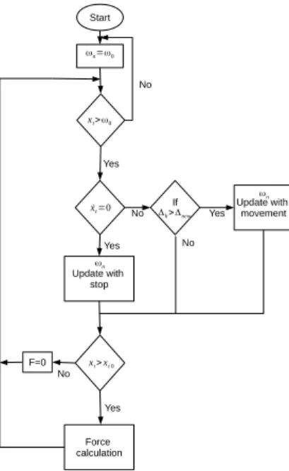
body. With these parameters, it is now possible to detail the operation of the tracking wall algorithm. Fig. 4 shows
Δh Δh =Δnew Δh new Δ new Δ x(t) x(t) x(t) Δh ωn ωn ωn 1) 2) 3) Δh Δh >Δnew Δh ωn x(t) x(t) ωn 4) 5) Δh Δh x(t) x(t) ωn ωn 6) 7) x(t) ωn 8) ω0 ω0 ω0 ω0 ω0 ω0 ω0 ω0
Figure 3. Evolution of a needle insertion, step by step, with the state of the virtual spring.
the flow diagram of the algorithm. The steps are as fol-lows:
1. Initial conditions: ωn= ω0.
2. When the tool overpassed ω0, the force exerted is
calculated using (7) and is updated in each iteration of the algorithm.
3. The tool continues its trajectory through the virtual body. The algorithm compares∆hagainst∆new.
4. If∆h > ∆new, it means that the tool has overpassed
the “safety position”, also the system is exerting the desired force for this layer
5. The tool continues its trajectory and now the value ωnis updated using (3).
6. When the system detects that the tool velocity is zero ( ˙xt = 0), meaning that the user stopped its
mo-tion. The position is saved as xt0, and the algorithm
computes ωnto update the wall using (6), while the
speed remains in null.
7. When the user moves again the tool, the algorithm compares the actual position xt with the value xt0
saved when the stop occurred. The value xt0 helps
to memorize the position of the needle.
8. if xt < xt0, the force exerted is null, that means
that the tool is retreated and then moved forward but not enough to start to cut new skin or muscle, but if xt> xt0the force is calculated and the process
restart from step 2.
Fig. 3 shows a graphical representation of the algo-rithm steps, where each number of the figure correspond to each number of the step described aforementioned.
If Update with movement ˙xt=0 xt>ω0 ωn=ω0 Δh>Δnew No ωn Yes Update with stop ωn Force calculation Yes Yes Start Yes xt>xt 0 F=0 No No No
Figure 4. Flow Diagram of Tracking Wall algorithm.
3 Experimental results
To validate this algorithm, a Virtuose™ 6D Desktop, is used. The algorithm is implemented in Matlab Simulink®, using the library developed by the provider.
3.1 Needle insertion
The force profile used to test tracking wall were obtained from the experiments made by [6]. In this paper authors, performed a needle insertion, and got the cutting force and the thickness between layers, obtaining a graphic of force and displacements. The parameters taken from this test which are applied on tracking wall method are, the cutting force 1 N and the thickness of the layer 12 mm. With these parameters it is possible to tune Ktto calculate∆new.
The stiffness value is Kt = 500 N/m (tuned value), the
desired force is 1 N and the∆new= 2 mm that is the value
calculated after applied (4) and the wall (virtual set point) is located in ωn= 0 mm.
Fig.5 shows the results obtained along 1-DoF using the values aforementioned. In this test the needle is in free motion from −50 mm to 0, therefore the value of ωnand
ω0remains null.
Once the needle gets into the pink zone (virtual shoul-der) the force is computed raising his value softly as long the needle is moving, reaching the desired force from t = 0.7s to t = 1.3s. This test helps to see how the al-gorithm updates the position of ωn.
3.2 Needle insertion with a stop
The second experiment concerns the response of the wall and the behavior of the force when a stop occurs inside the virtual limb. As can be seen in Fig. 6 this test uses the same parameter of Kt,∆newand the desired force, setting
Figure 5. First stage of needle insertion (1 dof)
Figure 6. Tracking wall in 1-DoF with stops inside the body
force begins to increase until the desired value which is reached t= 2.8s. At t = 4.5s the needle stops, and speed and force decreased to zero. Then at t= 5.3 s, the needle started again its movement and the force begins to increase gradually as well as the speed.
3.3 Stop and backward motion
Fig. 7 shows the behavior of the tool when a stop occurred inside the body. In the zoomed area one can observe the distance between the actual position and the ωn position,
that distance is the value of∆new= 2 mm, thus when the
user stops within the body, m is computed updating the value of ωnto equal the actual position and decrementing
the force value. However, in our case, we search to repli-cate the needle rejection motion when the user stops within the body. This is due to the muscles behavior. Therefore, mis computed using n > 10 · 106 in order to obtain the
desired behavior. Afterward, the tool is moved back and then moved forward. As the needle tip cut previously the same tissue, no force is applied until the tool position goes beyond the saved position.
3.4 Tracking wall in 3-DoF
A fourth test is performed in a 3-DoF case. For this test, a virtual shoulder is represented as a hemisphere with a ra-dius of 0.15m (Fig (8)). In this virtual shoulder, nine inner layers represent the different tissues and the limits of it. The desired forces for each layer are 1.5 N, 1 N, 1.8 N, 2 N, 3 N, 3.5N, 2.5 N, 4 N, and 4.5 N respectively. These values are arbitrarily chosen and are easily customized to reproduce different patients. The first layer represents the contact zone (pink shaded area Fig. 9) that helps the user
2 4 6 8 10 Time (s) 0 50 100 D isp la c e m e nt ( m m ) Px Wx 2 4 6 8 10 Time (s) 0 0.5 1 F o rc e ( N) Force 2.6 2.8 42 44 46 48 50 52 54
Figure 7. Illustration of the effect of stop and backward motions.
0 -0.2 0.05 0.1 Displacement "Y" (m) 0.15 0.4 Virtual shoulder 0.2 Displacement "x" (m) 0 0.3 Displacement "Z" (m) 0.2 0.2 0.1 End X: 0.05 Y: 0.275 Z: 0.1183 Start
Figure 8. Virtual shoulder and trajectory
0 0.5 1 1.5 2 2.5 3 3.5 4 4.5 5 Time (s) -0.1 0 0.1 0.2 0.3 P o sit io n / W a ll ( m ) Px Wx Py Wy Pz Wz 0 0.5 1 1.5 2 2.5 3 3.5 4 Time (s) -2 0 2 4 6 F o rc e ( N) Fx Fy Fz |F|
Figure 9. Tracking wall in 3-DoF: Positions and forces in axis X, Y and Z.
to feel the borders of it. The user must apply more force as the needle penetrates in each layer. When the user reaches the ninth layer the needle is pulled off from the virtual en-vironment following the same trajectory as it was inserted. To avoid any direction modification, a virtual fixture is implemented as proposes in [14]. It allows keeping the initial inclination in applying radial forces on the needle.
The results are shown in Fig. 9 where it can be ap-preciated the needle displacement in Px, Py, Pz with their corresponding tracking walls ωnx, ωnyωnzand the desired
forces in x,y, and z. As can be seen, the force magnitude is computed to corroborate the desired forces ( purple dot line).
In this test the user is able to feel the different stiffness within the shoulder, as long as his movement gets deeper, the forces change gradually allowing him to feel the be-havior of the force.
4 CONCLUSION
The proposed method, called Tracking Wall, helps to re-produce the desired cutting force that is exerted on the nee-dle tip. This method, avoid the use of any damper to dissi-pate the energy when the user stops his movement, instead of it, the parameter ωnis computed which is the position of
the wall that tracks the position of the virtual tool. Using this wall, the user can perform stops inside the limb and the rejection will be minimal, instead of the full trajectory as it happens with spring and dampers approaches. As fu-ture work, a campaign of measurement will be performed with the participation of experienced physicians and med-ical students. The objective is to measure how much this method is close to real life applications and evaluate how much it can help to improve their skills.
ACKNOWLEDGMENT
The authors would like to thank the ANR (French National Research Agency) for financing SAMSEI project (ANR-11-IDFI-0034) under the supervision of Pr. X. Martin.
References
[1] Y. Kurita, H. Ohtsuka, K. Nagata, T. Tsuji, Hap-tic rendering of a needle insertion by enhancing the real force response of a base object, in Haptics Sym-posium 2014, HAPTICS 2014(2014), pp. 357–360, ISBN 9781479931316, ISSN 23247355
[2] B. Gonenc, H. Gurocak, Haptic interface with hy-brid actuator for virtual needle insertion and tis-sue cutting, in Haptics Symposium 2012, HAPTICS 2012 - Proceedings (2012), pp. 451–455, ISBN 9781467308090
[3] E.K. Tveitå, R. Tariq, S. Sesseng, N.G.
Juel, E. Bautz-Holter, Hydrodilatation, cor-ticosteroids and adhesive capsulitis: A
ran-domized controlled trial, in BMC
Muscu-loskeletal Disorders (2008), Vol. 9, p. 53,
ISBN 1471-2474, ISSN 1471-2474, http:
//bmcmusculoskeletdisord.biomedcentral. com/articles/10.1186/1471-2474-9-53 [4] M. Martinez, G.R. Doulatram, Essentials of
Inter-ventional Techniques in Managing Chronic Pain pp. 471–479 (2018)
[5] J.C. Granry, M.C. Moll, Tech. rep., Haute Autorité de la Santé (HAS) (2012)
[6] H. Kataoka, T. Washio, K. Chinzei, K. Mizuhara, C. Simone, A.M. Okamura, Measurement of the Tip and Friction Force Acting on a Needle dur-ing Penetration, in Lecture Notes and Computer
Science (2002), pp. 216–223, ISBN 3540442243, ISSN 16113349, http://link.springer.com/ 10.1007/3-540-45786-0{\_}27
[7] C. Zilles, J. Salisbury, A constraint-based god-object method for haptic display, in Proceedings 1995 IEEE/RSJ International Conference on Intelligent Robots and Systems. Human Robot Interaction and Cooperative Robots (1995), Vol. 3, pp. 146–151, ISBN 0-8186-7108-4
[8] H. Courtecuisse, H. Jung, J. Allard, C. Duriez, Y. Lee, S. Cotin, GPU-based Real-Time Soft Tis-sue Deformation with Cutting and Haptic Feedback. GPU-based Real-Time Soft Tissue Deformation with Cutting and Haptic Feedback GPU-based Real-Time Soft Tissue Deformation with Cutting and Haptic Feedback, in Special Issue on Biomechanical Mod-elling of Soft Tissue Motion (Elsevier, 2010), Vol. 103, https://hal.inria.fr/hal-00686056 [9] D. Zerbato, P. Fiorini, A unified representation to
in-teract with simulated deformable objects in virtual environments, in Proceedings - IEEE International Conference on Robotics and Automation(2016), Vol. 2016-June, pp. 2710–2717, ISBN 9781467380263, ISSN 10504729
[10] D. Lobo, M. Sarac, M. Verschoor, M. Solazzi, A. Frisoli, M.A. Otaduy, Proxy-based haptic render-ing for underactuated haptic devices, in 2017 IEEE World Haptics Conference, WHC 2017 (2017), pp. 48–53, ISBN 9781509014255
[11] A. Hernansanz, D. Zerbato, L. Gasperotti, M. Scan-dola, P. Fiorini, A. Casals, Improving the develop-ment of surgical skills with virtual fixtures in simula-tion, in Lecture Notes in Computer Science (includ-ing subseries Lecture Notes in Artificial Intelligence and Lecture Notes in Bioinformatics) (2012), Vol. 7330 LNCS, pp. 157–166, ISBN 9783642306174, ISSN 03029743
[12] H. Li, K. Kawashima, Bilateral teleoperation with delayed force feedback using time domain passiv-ity controller, in Robotics and Computer-Integrated Manufacturing(2016), ISSN 07365845
[13] K.J. Kuchenbecker, J. Fiene, G. Niemeyer, Improv-ing contact realism through event-based haptic feed-back, in IEEE Transactions on Visualization and Computer Graphics (2006), Vol. 12, pp. 219–229, ISBN 1077-2626 VO - 12, ISSN 10772626
[14] R. Kikuuwe, N. Takesue, H. Fujimoto, Passive vir-tual fixtures based on simulated position-dependent anisotropic plasticity, in Proceedings - IEEE Inter-national Conference on Robotics and Automation (2007), pp. 3263–3268, ISBN 1424406021, ISSN 10504729
![Figure 1. Needle insertion in the shoulder ([4]).](https://thumb-eu.123doks.com/thumbv2/123doknet/14423878.513817/2.892.534.735.570.751/figure-needle-insertion-in-the-shoulder.webp)