HAL Id: cea-01695847
https://hal-cea.archives-ouvertes.fr/cea-01695847
Submitted on 4 Jan 2021HAL is a multi-disciplinary open access archive for the deposit and dissemination of sci-entific research documents, whether they are pub-lished or not. The documents may come from teaching and research institutions in France or abroad, or from public or private research centers.
L’archive ouverte pluridisciplinaire HAL, est destinée au dépôt et à la diffusion de documents scientifiques de niveau recherche, publiés ou non, émanant des établissements d’enseignement et de recherche français ou étrangers, des laboratoires publics ou privés.
by Assembly of Chitosan-Collagen Microspheres
Produced by Microfluidics
David Azria, Raluca Guermache, Sophie Raisin, Sébastien Blanquer, Frédéric
Gobeaux, Marie Morille, Emmanuel Belamie
To cite this version:
David Azria, Raluca Guermache, Sophie Raisin, Sébastien Blanquer, Frédéric Gobeaux, et al.. Elab-oration of Materials with Functionality Gradients by Assembly of Chitosan-Collagen Microspheres Produced by Microfluidics. Journal of Renewable Materials, Scrivener publishing, 2018, 6 (3), pp.314-324. �10.7569/JRM.2017.634186�. �cea-01695847�
DOI: 10.7569/JRM.2017.634186 DOI: 10.7569/JRM.2017.634186
*Corresponding author: emmanuel.belamie@enscm.fr
Assembly of Chitosan-Collagen Microspheres Produced by
Microfluidics
David Azria1,2, Raluca Guermache1,2, Sophie Raisin1, Sébastien Blanquer1, Frédéric Gobeaux3, Marie Morille1 and Emmanuel Belamie1,2,*
1ICGM-MACS, UMR 5253 CNRS-ENSCM-UM, Charles Gerhardt Institute Montpellier, 8 rue de l’Ecole normale, 34296 Montpellier cedex 5, France
2Ecole Pratique des Hautes Etudes, PSL Research University, 75014 Paris, France
3LIONS—NIMBE CEA, CNRS, University of Paris-Saclay, CEA Saclay, 91191 Gif-sur-Yvette, France
Received May 31, 2017; Accepted November 24, 2017
ABSTRACT: Biopolymers extracted from renewable resources like chitosan and collagen exhibit interesting properties
for the elaboration of materials designed for tissue engineering applications, among which are their
hydrophilicity, biocompatibility and biodegradability. In many cases, functional recovery of an injured tissue or organ requires oriented cell outgrowth, which is particularly critical for nerve regeneration. Therefore, there is a growing interest for the elaboration of materials exhibiting functionalization gradients able to guide cells. Here, we explore an original way of elaborating such gradients by assembling particles from a library of functionalized microspheres. We propose a simple process to prepare chitosan-collagen hybrid microspheres by micro- and milli-fluidics, with adaptable dimensions and narrow size distributions. The adhesion and survival rate of PC12 cells on hybrid microspheres were compared to those on pure chitosan ones. Finally, functionalized microspheres were assembled into membranes exhibiting a functionalization gradient.
KEYWORDS: Hybrid microspheres, biomaterials, chitosan, collagen, functionality gradient, nerve regeneration,
microfluidics
1 INTRODUCTION
Materials can be elaborated with physical (topology, dimensionality, rigidity), chemical and biochemical cues designed to orient the behavior of cells [1–4]. More specifically, the control of neural differentiation and the guidance of neurite outgrowth is a very active research field [5–10]. It has been shown in many previ-ous works that immobilized gradients of growth fac-tors can induce the differentiation of neural cells and orient the neuritic outgrowth along the growth factor gradient [6, 7, 11, 12]. The generation of growth factor gradients has been achieved by several approaches, including microfabrication [13], the surface modifica-tion of polymers [6] or microfluidic technologies [14], providing a whole range of materials well adapted for
in-vitro cellular studies. Fewer, however, are truly suited
for in-vivo use as implantable material to promote and
guide nerve tissue regeneration. Hydrogels composed of biopolymers like chitosan and collagen have the advantage of being hydrophilic, biocompatible and biodegradable. Chitosan is a derivative of chitin, a very abundant polysaccharide generated as an indus-trial waste in large fisheries. As an example, the annual production of crustacean shell processing wastes by the Indian seafood industry amounts to about 100,000 tons/year [15]. Chitosan, as well as its chemical deriv-atives [16], have long been demonstrated to be highly relevant candidates for biomedical applications [17]. Apart from showing excellent biocompatibility and being bioresorbable, chitosan also exhibits one main functional group (amine –NH2) highly suited for site-specific modification using EDC-based coupling techniques. Because the pKa of the amine group is roughly comprised between 6 and 7.5 depending on its degree of acetylation [18], chitosan is readily solu-ble at acidic pH and precipitates at neutral and basic pH. Collagen is a protein present in major extracellu-lar matrices (ECM) like skin, bone or tendon, in the form of fibrils. Most cells express specific collagen
receptors, called integrins, which are located at the cell membrane. Noncovalent interactions of the extra-cellular part of integrins with collagen fibrils provide anchoring points to the cells within the matrix, thus promoting cell adhesion. Collagen is often extracted from rat tail tendon for academic research purposes, but it is also available as an industrial product from bovine and porcine sources. Collagen is a triple heli-cal protein which can be dissolved in acidic aqueous solutions and precipitate in the form of striated fibrils over a wide pH range around neutrality (6–12) [19]. This pH-induced precipitation of fibrils is associated with the formation of elastic gels, provided the colla-gen concentration is high enough, ca. ~10 mg/ml. Like chitosan, it is largely used for biomedical applications [20, 21], among which is nerve regeneration [21, 22].
In the present work, our intent was to generate microspheres as a cell-supporting material through a microfluidic-based process. Collagen was success-fully used in a microfluidic device at a concentra-tion of 3.5 mg/ml to encapsulate cells [23]. However, collagen solutions at a concentration high enough to produce strong gels suitable for material assembly (~10 mg/ml) are strongly viscoelastic [24] and diffi-cult to handle in microfluidic devices. An alternative would be to use solutions at a much lower concentra-tion, hence less viscous, and to covalently crosslink the particles with chemical agents like glutaraldehyde. To avoid the use of potentially toxic chemicals for the for-mation of stable microspheres, we studied the possi-bility to process chitosan solutions into microspheres by microfluidics and incorporate small amounts of col-lagen. This hybrid composition is attractive because it combines the relatively low viscosity of chitosan solutions with the property of collagen to promote cell adhesion. Such a combination has already proven suitable to support cell adhesion and tissue regenera-tion [25, 26].
Hydrogels formulated as microparticles offer the advantages of high surface area and injectabil-ity. The assembly of microparticles also provides an opportunity to generate materials with multiple func-tionalities without the necessity of site-specific post-modifications. This approach can be an interesting alternative to microprocessing techniques, like bio-printing, when the sensibility of biopolymers to pro-cessing conditions (high temperature, electric fields, light irradiation…) can be an issue. Milli- and micro-fluidic devices can be used to generate emulsions with controlled and homogenous dimensions. The charac-teristics and properties of the resulting materials are influenced by both intrinsic properties of the poly-mers, like their viscosity and ability to form gels, as well as processing parameters like the chip geometry and flow rates [27].
Here we studied the formation of chitosan micro-spheres by solidification of an acidic emulsion by raising the pH. In this process, we used no cova-lent crosslinking agent to stabilize the microspheres. Collagen was added to the initial chitosan acidic solu-tion to elaborate hybrid particles and enhance cell adhesion by providing biochemical cues reminiscent of the extracellular matrix. We investigated the effect of mixing the two biopolymers on the processing condi-tions and resulting microspheres’ morphology, dimen-sions and the biopolymers repartition. Cell adhesion was qualitatively assessed for both kinds of micro-spheres with PC12 cells. Finally, micromicro-spheres were modified and assembled to elaborate materials exhib-iting a functionalization gradient. The proof of concept was demonstrated with a fluorescent dye covalently attached to the microspheres and then extended to a model protein.
2 EXPERIMENTAL
2.1 Biopolymers
• Chitosan powder (France Chitin, batch # 342) was solubilized in 0.1 M HCl, and the resulting solution successively filtrated on 8 µm, 0.8 µm, 0.45 µm and 0.22 µm membranes to remove insolubles. To regenerate the free amine form, chitosan was then precipitated by adding 10 M NaOH under stirring (1500 rpm) until pH 10 and the precipitate was retrieved by centrifu-gation at 3900 × g for 20 min. The pellets were rinsed twice with a large volume of Milli-Q water, frozen at –80 °C for 48 h, and finally freeze-dried. Sample solutions were prepared from ground chitosan powder solubilized in 0.5 M acetic acid. A molecular weight of 260 kDa was determined by SEC-MALLS (size exclusion chromatography coupled with mul-tiangle laser light scattering) using an UHPLC Thermo Scientific Dionex UltiMate 3000 with a Shimadzu RID-20A RI Detector and Wyatt miniDAWN TREOS MALLS instrument, GE Healthcare Superdex 200 10/300 GL column and an acetate buffer as the mobile phase (ace-tic acid 0.2 M, ammonium acetate 0.15 M, pH 4.5, 0.02 % NaN3). Intrinsic viscosity of 11.1 dl/g was calculated by measuring dynamic viscosity at increasing concentrations (from 0.1 to 0.7 g/dl) with an Anton Paar rheometer in the cone-plate geometry (mobile CP50-1: diameter of 49.966 mm, cone angle 0.990°, cone truncation 99 µm). The deacetylation degree was determined at around 80 % by 1H NMR according to the method presented in [28].
• Type I collagen was extracted and purified from young rat tail tendons following a proto-col previously published [19]. Briefly, tendons were excised from the tail by dislocating the vertebrae, extensively rinsed in sterile phos-phate-buffered saline (PBS) buffer to remove cells and traces of blood. Remaining cells were lysed by soaking the extracted tendons in NaCl 4 M followed by extensive washing with PBS before solubilization of the collagen in 0.5 M acetic acid. The resulting solution was clarified by centrifugation (21,000 × g for 2 h) to eliminate aggregates and collagen fur-ther purified from ofur-ther proteins by selective precipitation. An acidic solution was finally prepared at 9 mg/ml in 0.5 M acetic acid by reverse osmosis against 50 g/l PEG 20 kDa. Collagen concentration was determined from the acidic solution before fibrillogenesis by assessing the amount of hydroxyproline [29]. • Hybrid solutions were prepared with a
chitosan:collagen mass ratio of 9:1. Chitosan and collagen solutions were prepared in ace-tic acid 0.5 M, mixed under magneace-tic stirring (250 rpm, at least 24 hours) to obtain a solution with a total polymer concentration (chitosan + collagen) of 2.1 % w/v (pH 3.88). To assess the homogeneity of the final solution, chitosan was labeled with fluorescein isothiocyanate (FITC) fluorochrome (1 FITC/2000 chitosan amine groups), and collagen with tetramethylrho-damine isothiocyanate (TRITC) (1 FITC/5000 collagen amine groups). The resulting micro-spheres were imaged by confocal microscopy (Leica Confocal SPE) at a 1024 × 1024 pixels resolution with 41 slices in the Z-dimension (Z stack), corresponding to a voxel size of 179.2 × 179.2 × 4657.7 nm. 3D image reconstruction was done with ImageJ.
2.2 Milli- and Micro-Fluidics
• Microfluidic chips were prepared with Silicone (Sylgard 184 PDMS, Dow Corning) and 10 % hardening agent degassed by centrifugation (1000 rpm at ambient temperature), poured into a master mold and degassed again under vacuum for 10 min. The silicone was cured at 65 °C for 45 min, individual circuit chips were removed from the master mold before entrance and exit holes were punched. Individual chips were finally attached to a glass slide activated by plasma treatment (Dierner Plasma Femto 1). The emulsion was generated thanks to a flow-focusing geometry, and the lateral dimensions
of the junction were either 50 × 50 µm² or 100 × 100 µm² (respectively referred to as T50 and T100). Channel height was 76–80 µm, as determined by interferometry.
• T-junction:PEEK MicroTee (1/16 in) device (Upchurch) with a thru hole of 150 µm and cor-responding tubing (1/16 in) were alternatively used to generate the emulsion. Before use, the inner surfaces of all fluidic parts were washed with pure acetic acid, dried at 80 °C overnight, coated with Sigmacote (Sigma, France) cured for 40 min at 80 °C to prevent wetting by the polymer solution.
• Microspheres were produced with either a microfluidic chip or MicroTee device. Perfluorinated oil (3M™ Novec™ 7500 Engineered Fluid) was used as the oil phase with 1 wt% of a triblock copolymer surfactant synthesized in the lab according to a previously published protocol [30]. Unless otherwise stated, the flow rates were 0.02 ml/min for the oil phase and 0.002 ml/min for the aque-ous phase. Both solutions were pumped into the milli-/micro-fluidic devices with a push syringe (Harvard Apparatus). Emulsion drop-lets were collected in a plastic Petri dish, cov-ered with a layer of silicone oil. The Petri dish was then placed in an ammonia atmosphere to increase the pH and induce the precipitation of chitosan and the fibrillation of collagen. The solidified microspheres were then separated from the oil by cycles of centrifugation and washing with PBS.
• The dimensions and size distributions of emulsion droplets and microspheres were determined by measurements performed on microscope images obtained with a Leica inverted microscope equipped with a CCD camera. Mean diameter and standard devia-tion were calculated from at least 100 measure-ments for droplets and 50 for microspheres. • Functionalization procedures: To visualize
the formation of functionalization gradients, hybrid microspheres were labeled directly with a fluorescent probe (FITC) or with a model protein bovine serum albumin (BSA) itself modified with FITC (Sigma-Aldrich, A9771). Briefly, FITC was first dissolved in eth-anol at 10 mg/ml, then diluted at 0.1 mg/ml in morpholinoethanesulfonic acid (MES 10 mM, pH 6). The required amount of FITC (from 1 FITC/2000 chitosan amine groups to 1/40000) was mixed with 50,000 microspheres sus-pended in PBS (final ratio MES:PBS of 25:75) under rotative agitation (10 rpm) overnight,
protected from light. Microspheres were then rinsed 3 times with PBS to remove noncova-lently bound fluorescein. Similarly, BSA-FITC was grafted onto microspheres. In MES 10 mM, succinic acid was activated with EDC (N-(3-Dimethylaminopropyl)-N′-ethylcarbodiimide hydrochloride) and reacted with microspheres suspended in PBS (final ratio of MES:PBS was 25:75) and molar ratio BSA-FITC:succinic acid:EDC was 1:10:80.
• Assembly of scaffold with function gradient: Microspheres were assembled by sedimen-tation and chemically crosslinked in a mold composed of two glass slides separated by a 0.8 mm thick U-shape spacer. Reticulation agents used were glutaraldehyde (at a 0.25 % final concentration) or succinic acid (60 mM) activated with EDC (240 mM). The mold con-taining microspheres and reticulation agent was centrifuged at 1600 g for 5 min at ambi-ent temperature. After one hour of reaction, the assembled membranes were unmolded and extensively rinsed with PBS.
2.3 Cell Culture and Observations
• PC12 cells were cultured in DMEM completed with 10 % horse serum, 5 % fetal bovine serum, 1 % glutamine and 1 % penicillin/streptomy-cin. PC12 cell adhesion onto microspheres was assessed in DMEM 1 % glutamine and 1 % pen-icillin/streptomycin in Ultra-Low Adhesion 24-wells plates. The medium was removed and cells/microspheres were fixed with 1 ml
paraformaldehyde 3.7 % for 20 min, washed three times with PBS and transferred into 1.5 ml tubes. Cells/microspheres were stained with DAPI (1 ml at 1 µg/ml, 5 min) and washed three times with PBS. Observations of cell cul-ture and cell adhesion onto microspheres were assessed with a EVOS FL Cell Imaging System (Thermo Fisher Scientific).
3 RESULTS AND DISCUSSION
3.1 Elaboration of Microspheres by
Microfluidics
The microspheres were obtained by the initial for-mation of an emulsion with the biopolymers in the aqueous phase at acidic pH followed by solidifica-tion of the droplets. Both chitosan and collagen are soluble in acidic aqueous media but insoluble at neutral pH. The simplest way of solidifying the droplets was thus to induce a pH increase, which can be obtained by placing the acidic emulsion in the presence of ammonia vapors. This process allowed for the preparation of pure chitosan microspheres (Figure 2b) and of hybrid chitosan-collagen micro-spheres (Figure 2d) without chemical crosslinking agent, provided the initial biopolymers concentra-tion was high enough to produce solids (gels) upon precipitation [31].
With both chitosan and hybrid solutions, homo-geneous emulsions were produced (Figure 2a,e) with similar droplet size (Table 1). After precipitation by exposition to ammonia vapors, solid microspheres
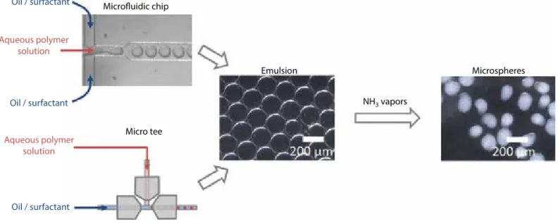
Figure 1 General scheme for formation of microspheres: The initial emulsion is obtained with an acidic polymer solution and
oil/surfactant mixture, with either a microfluidic chip or a MicroTee device. Microspheres are then obtained by solidifying the emulsion under ammonia vapors.
Microfluidic chip Emulsion NH3 vapors Microspheres Micro tee Oil / surfactant Oil / surfactant Oil / surfactant Aqueous polymer solution Aqueous polymer solution
were formed and could be separated from the oil phase by filtration and successive rinsing steps.
As the pH-induced sol-gel transition proceeds, the droplets clearly shrink and slightly deform as the bio-polymers precipitate forming hydrogel microparticles (Figure 2b,d). This shrinkage, reported in Table 1,
amounts to approximately 20–25 % of the initial drop-let size for chitosan microspheres. It mostly results from the reduction of repulsive interactions as the pH goes beyond the pKa of chitosan and solvent released, as largely described previously. Apparently, despite a slight deformation of the initial spherical morphology
Figure 2 Images of emulsion droplets and microspheres generated with the T-junction millifluidic device: (a) chitosan emulsion,
(b) chitosan microspheres after ammonia vapors, (c) chitosan-collagen hybrid emulsion, (d) hybrid microspheres after ammonia vapors. Micrographs (a–d) were taken under darkfield illumination. Scale bar: 500 µm.
(a) (b)
(c) (d)
Table 1 Emulsion droplet and microsphere size as a function of flow rates. Qc/Qd is the flow rate ratio between the oil
(continu-ous phase Qc) and chitosan or hybrid (chitosan:collagen, 9:1) aque(continu-ous phase (dispersed phase Qd). The emulsion was obtained with either a microfluidic chip, 100 × 100 µm2 (T 100) or 50×50 µm2 (T 50) or a MicroTee device.
Chitosan
Flow rates (ml.min–1) Diameter ± SD (µm) Size reduction / NH3 (%)
Qc Qd Qc/Qd Emulsion µ-Spheres Chip T 50 0.05 0.002 25 60.67 ± 0.26 49.99 ± 5.88 18 0.06 0.002 30 61.76 ± 3.01 52.29 ± 1.84 15 0.07 0.002 35 57.55 ± 1.77 49 ± 1.37 15 Chip T 100 0.01 0.002 5 103.96 ± 3.83 81.08 ± 7.85 22 0.02 0.002 10 95.24 ± 11.94 73.61 ± 11.48 23 0.02 0.002 10 94.55 ± 10.81 68.61 ± 7.84 27 0.02 0.003 6.67 101.44 ± 2.87 76 ± 7.09 25 0.02 0.004 5 173.12 ± 5.32 140.62 ± 11.4 19 0.03 0.002 15 81.96 ± 5.7 62.54 ± 6.49 24 0.04 0.002 20 91.17 ± 9.74 68.46 ± 6.83 25 MicroTee 0.02 0.002 10 175.26 ± 10.2 135.03 ± 23.4 23 Hybrid Chip T 100 0.02 0.002 10 152.44 ± 2.99 124.74 ± 3.27 18 0.04 0.002 20 130.22 ± 2.93 97.43 ± 26.96 25 0.06 0.002 30 95.81 ± 10.69 67.41 ± 31.8 30 MicroTee 0.02 0.002 10 173.56 ± 4.9 136.24 ± 15.1 21
of the droplets, the surface of the particles remains mostly smooth.
Emulsion droplet size and microspheres’ dimen-sions are reported in Table 1 and their variations stud-ied as a function of the respective flow rates of the chitosan solution and oil/surfactant mixture.
In the conditions investigated here, the micro-sphere diameter roughly ranges between 50 and 150 µm depending on the microfluidic chip geometry and respective phases flow rate. The overall trend is that for a fixed oil flow rate (“Qc”), increasing the chito-san flow rate (“Qd”) results in increased particle size (Figure 3a). Similarly, increasing the oil flow rate at fixed chitosan flow rate produces smaller droplets. Therefore, the ratio Qc/Qd is the relevant parameter, in agreement with previous works [32–35].
Hybrid chitosan-collagen microspheres were pre-pared following the same procedure but with a mixed solution of collagen and chitosan (9:1) as the aque-ous phase for the emulsion. The addition of a small proportion of collagen to the chitosan solution was intended to promote cell adhesion while keeping the viscosity relatively low. In fact, preliminary unpub-lished results suggested that cells (mesenchymal stem cells and PC12) did not readily adhere to pure chito-san microspheres. The dimensions of microspheres are also dependent upon the respective flow rates of the aqueous and oil phases (Figure 4). This effect is even stronger compared to pure chitosan solutions.
To assess the homogeneity of the mixtures at acidic pH, their turbidity was evaluated by measur-ing the intensity of light scattered at 90° as a func-tion of the total polymer concentrafunc-tion for a fixed chitosan:collagen ratio of 9:1. Scattered light inten-sity increases linearly with increasing polymer
concentration, suggesting that the mixed solutions remain homogeneous. Indeed, the formation of large aggregate would drastically increase the scattered light intensity, which is not observed here, notably at the concentration (2.1 wt%) used to prepare the hybrid microspheres. In fact, at this concentration, the scattered light intensity for the hybrid solution (3032 ± 54) was only slightly larger than the sum of intensities scattered by the corresponding individual solutions of 1.9 wt% chitosan (2102 ± 123) and 0.22 wt% collagen (518 ± 230). It should be noted that the pH of the mixture increased from approx. 3 to 4 over the entire concentration range (0.25–3 wt%). In this pH range, the net charge of both polymers, chi-tosan and collagen, remains mostly unchanged and
Figure 3 Size of emulsion droplets (open symbols) and microspheres after ammonia vapors (solid symbols): (a) as a function
of chitosan solution flow rate at constant oil flow rate (0.02 ml.min–1) and (b) as a function of oil flow rate at constant chitosan
solution flow rate (0.002 ml.min–1). The emulsion was obtained on a microfluidic chip with a 100 × 100 µm2 (a, b) or 50 × 50 µm2
(c) cross design.
(a)
Droplet diameter (100x100) Microspheres diameter
Droplet diameter (100x100) Droplet diameter 50x50
Microspheres diameter 50x50 Microspheres diameter 100x100 120 100 80 60 40 0.04 0.05 0.06 0.07
Oil rate (ml/min.)
0.01 0.02 0.03 0.04 0.05 0.06 0.07 180 160 140 120 100 80 60
Chitosan rate (ml/min)
0.002 0.003 0.004 Dr oplet diameter (100x100) (µ m) Diameter (µ m) (b) (c)
Figure 4 Size of hybrid chitosan-collagen emulsion droplets
(crossed open circle) and microspheres after ammonia vapors (solid circles) as a function of oil flow rate at constant chitosan solution flow rate (0.002 ml.min–1). Chip 100 × 100
µm2 cross design.
Hybrid droplet diameter Hybrid microspheres diameter 140 160 120 100 80 60 40
Oil rate (ml/min.)
Diameter
(µ
m)
no particular change in behavior is thus expected. However, this does not rule out the possibility of local association between the charged amino groups of chitosan and partly charged acidic side chains from collagen (aspartatic or glutamic acid), resulting in a slight increase in scattered light. The repartition of the two polymers after solidification of the droplets was assessed by confocal microscopy observations of hybrid microspheres with a dual fluorescence labeling of chitosan (green, FITC) and collagen (red, TRITC) with chitosan-FITC:collagen-TRITC ratio of 9:1. The separate channels and overlay clearly indi-cate a homogenous co-localization of chitosan and collagen at the micrometer level (Figure 5b).
3.2 Cell Adhesion
Because the materials (chitosan and hybrid chitosan-collagen) are intended to support the differentiation of neural cells, we investigated the adhesion and survival of model PC12 cells on the microspheres. It should be noted that in the absence of microspheres, the cell culture plates being treated to prevent adhe-sion, the cells tend to form aggregates that remain in suspension. In the presence of microspheres, part of the cells adheres to the biopolymers surface. Cells in excess either remain in the medium and aggre-gate into dense clusters or form bridges between the microspheres (Figure 6). The adhesion rate is clearly
Figure 5 (a) Homogeneity of chitosan-FITC:collagen-TRITC solutions assessed by light scattering measurements as a function of
total polymer concentration in wt%. (b) Maximum intensity projection of a Z-stack of 41 successive slices of a hybrid microsphere imaged by confocal microscopy, with collagen labeled in red (left), chitosan in green (center) and overlay (right). The bar is 50 µm.
(a) (b) 5000 4000 3000 2000 1000 0
Total polymer concentration (w%)
Sc
attered intensit
y (kcps)
0.0 0.5 1.0 1.5 2.0 2.5 3.0
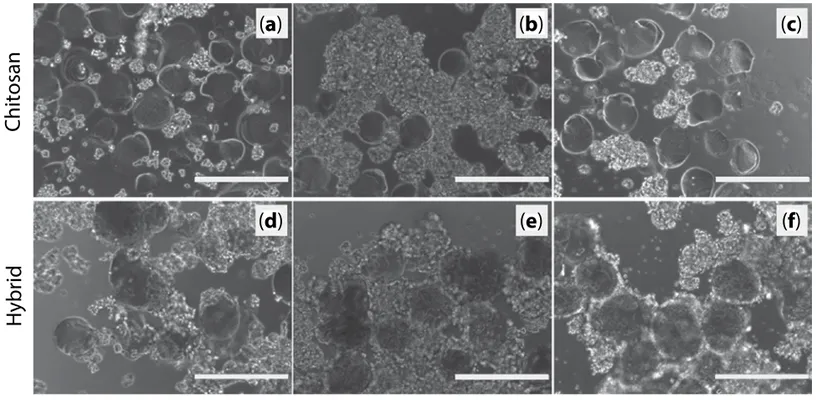
Figure 6 Optical micrographs of PC12 cells in the presence of microspheres made of either pure chitosan (a–c) or
chitosan-collagen mixtures (d–f) after 24 h (a, d), 48 h (b, e) and 74 h (c, f) of incubation.
Chitosan
(a)
(b)
(c)
(d)
(e)
(f)
higher with hybrid particles (containing collagen) compared to pure chitosan ones, which is quanti-tatively confirmed in Figure 7. Chitosan has been largely described as a suitable biopolymer to elabo-rate implantable scaffolds for tissue regeneration [16, 36–38]. However, several previous studies have pointed out a rather low cell adhesion rate on the sur-face of chitosan hydrogel [39], which was compen-sated, for instance, by grafting adhesion peptides [40, 41] or addition of ECM molecules like collagen [42] or gelatin [39]. Additionally, a CyQUANT cell-counting assay revealed that cell survival is promoted by the presence of microspheres, the cell count after 24 hours in low adhesion culture plates being 6.59 ± 1.17 × 10⁴ cells in the absence of microspheres, 8.53 ± 1.40 × 10⁴ with chitosan microspheres (×1.3) and 9.85 ± 1.28 × 10⁴ in the presence of hybrid microspheres (×1.5). Since the CyQUANT assay is based on total DNA content, the total cell count is a combination of cell survival and proliferation. The reported doubling time for PC12 being approximately 92 hours [43], proliferation cannot account for the differences in cell count after 24 hours. Globally, in agreement with previous studies, our data indicate higher adhesion and survival rate in the presence of collagen combined with the chitosan microspheres.
3.3 Assembly and Gradient Formation
The present study was aimed at demonstrating the possibility of generating materials exhibiting protein functionalization gradients by assembling hydro-gel microspheres. Such materials are intended to guide cells, in particular neural cells, by imposing a
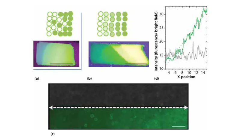
chemo-attractive effect inducing migration and/or differentiation along a preferred direction. More pre-cisely, the final objective was to elaborate tubular nerve guides. For practical reasons, we chose to first elabo-rate flat membranes that can be later rolled into tubular structures [36]. The membranes were obtained by the sedimentation of microspheres in a vertical flat mold and retrieved after crosslinking. To form gradients, we explored two routes: 1) mix gradually increasing proportions of functionalized microspheres with bare ones or 2) assemble successive layers of microspheres exhibiting an increasing level of functionalization (Figure 8a,b). We first optimized the assembly process with fluorescein-labeled microspheres (Figure 8a,b). Labeling with fluorescein was obtained by reacting the isothiocyanate moiety of FITC with the free amino groups of the biopolymers. The final objective being to functionalize the materials with active proteins such as growth factors, and in particular neurotrophins, using the same chemical approach. In the first instance, BSA was studied as a model protein to assess the efficiency of the coupling procedure. In this case, EDC was used to activate a diacid linker such as succinic acid. To graft the active protein onto the microspheres, one car-boxylic group of the diacid should react with a free amino group of BSA and the second carboxyl group with a free amino group from chitosan or collagen. Microspheres were prepared by this procedure with increasing functionalization levels and assembled into membranes (Figure 8c). The profile of fluorescence intensity measured along the microspheres deposition direction clearly exhibits a linear fluorescence gradient (Figure 8d). The fluorescence profile is clearly distinct from the profile of transmitted light intensity, which
Figure 7 Comparison of the number of PC12 cells adhered onto chitosan (solid bars) and chitosan-collagen hybrid (hatched
bars) microspheres after 4, 24 and 48 hours of culture.
Number of adhered cells / microspher
e Time (h) 0.0 0.5 1.0 1.5 2.0 2.5 4 24 48
appears noisy only because of variations in opacity at the micron scale due to the microspheres assembling.
4 CONCLUSIONS
Here we intended to demonstrate the possibility of elaborating materials exhibiting functionalization gra-dients by the assembly of microspheres of well-defined and adaptable dimensions. Contrary to bulk emulsion-based processes, the microspheres produced by micro- or milli-fluidic technologies show relatively narrow size distributions. In addition, the microsphere size could be varied by a factor of two by simply changing the flow rates of the solutions forming the emulsion. The solidification process, based on the precipitation of chitosan (with or without collagen added) by rais-ing the pH of the droplets by the diffusion of ammonia vapors, leaves amine functions available for further functionalization of the particles and assembly. Hybrid microspheres exhibit a uniform repartition of chitosan and collagen, owing to the homogeneity of the initial acidic mixed solutions. The presence of small collagen amounts does not strongly impact the microfluidic processing of the solutions, but largely improves cell adhesion. The resulting microspheres, labeled with a
fluorescent dye or conjugated to a protein, were suc-cessfully assembled into materials exhibiting function-alization gradients. This proof-of-concept study can be extended to the generation of materials exhibiting growth factor gradients suited for the elaboration of tubular structures intended to guide neural growth.
ACKNOWLEDGMENTS
The authors thank L. Vachoud (rheology) and P. Gonzalez (HPLC) For their help with chitosan charac-terization. AD acknowledges the EPHE for providing a PhD fellowship.
REFERENCES
1. M.P. Lutolf, P.M. Gilbert, and H.M. Blau, Designing materials to direct stem-cell fate. Nature 462, 433–441 (2009).
2. D. Seliktar, Designing cell-compatible hydrogels for biomedical applications. Science 336, 1124–1128 (2012). 3. M. Ventre, F. Causa, and P.A. Netti, Determinants of
cell–material crosstalk at the interface: Towards engi-neering of cell instructive materials. J. R. Soc. Interface
9, 2017–2032 (2012).
Figure 8 Formation of membranes with functionalization gradients either by mixing functionalized with non-functionalized
particles (a), or by varying the functionalization level (b–d). (a, b) Macroscopic images of the FITC-functionalized materials under UV illumination; (c) microscopic observations of a membrane from microspheres functionalized with increasing BSA-FITC levels (left to right) observed in transmitted light (upper panel) or fluorescence (lower panel, green) and corresponding fluorescence intensity profile (d, x-position unit is 10² µm) measured along the dashed white line in (c). Scale bars: a, b = 1 cm;
c = 400 µm. (a) (b) (d) X-position 10 15 20 25 30 4 6 8 10 12 14 In
tensity (flurescence/ bright field
)
4. X. Yao, R. Peng, and J. Ding, Cell–material interactions revealed via material techniques of surface patterning.
Adv. Mater. 25, 5257–5286 (2013).
5. S.L. Bechara, A. Judson, and K.C. Popat, Template syn-thesized poly(ε-caprolactone) nanowire surfaces for neural tissue engineering. Biomaterials 31, 3492–3501 (2010).
6. B. Delalat, A. Mierczynska, S.R. Ghaemi, A. Cavallaro, F.J. Harding, K. Vasilev, and N.H. Voelcker, Materials Displaying Neural Growth Factor Gradients and Applications in Neural Differentiation of Embryoid Body Cells. Adv. Funct. Mater. 25, 2737–2744 (2015). 7. N. Gomez, Y. Lu, S. Chen, and C. E. Schmidt,
Immobilized nerve growth factor and microtopogra-phy have distinct effects on polarization versus axon elongation in hippocampal cells in culture. Biomaterials
28, 271–284 (2007).
8. D.-H. Kim, H. Lee, Y.K. Lee, J.-M. Nam, and A. Levchenko, Biomimetic nanopatterns as enabling tools for analysis and control of live cells. Adv. Mater. 22, 4551–4566 (2010).
9. C.K. Yeung, L. Lauer, A. Offenhäusser, and W. Knoll, Modulation of the growth and guidance of rat brain stem neurons using patterned extracellular matrix pro-teins. Neurosci. Lett. 301, 147–150 (2001).
10. D. Santos, P. Wieringa, L. Moroni, X. Navarro, and J.D. Valle, PEOT/PBT guides enhance nerve regeneration in long gap defects. Adv. Healthc. Mater. 6(3), 1600298 (2017).
11. X. Cao and M.S. Shoichet, Defining the concentration gradient of nerve growth factor for guided neurite out-growth. Neuroscience 103, 831–840 (2001).
12. M.R. Wrobel and H.G. Sundararaghavan, Directed migration in neural tissue engineering. Tissue Eng. Part
B Rev. 20, 93–105 (2013).
13. W. Zhu, C. O’Brien, J.R. O’Brien, and L.G. Zhang, 3D nano/microfabrication techniques and nanobiomateri-als for neural tissue regeneration. Nanomed. 9, 859–875 (2014).
14. S. García, R. Sunyer, A. Olivares, J. Noailly, J. Atencia, and X. Trepat, Generation of stable orthogonal gra-dients of chemical concentration and substrate stiff-ness in a microfluidic device. Lab. Chip 15, 2606–2614 (2015).
15. M. H. Struszczyk, Chitin and chitosan. Part I. Properties and production. Polimery 47, 316–325 (2002).
16. I.-Y. Kim, S.-J. Seo, H.-S. Moon, M.-K. Yoo, I.-Y. Park, B.-C. Kim, and C.-S. Cho, Chitosan and its derivatives for tissue engineering applications. Biotechnol. Adv. 26, 1–21 (2008).
17. F. Croisier and C. Jérôme, Chitosan-based biomaterials for tissue engineering. Eur. Polym. J. 49, 780–792 (2013). 18. P. Sorlier, A. Denuzière, C. Viton, and A. Domard,
Relation between the degree of acetylation and the electrostatic properties of chitin and chitosan.
Biomacromolecules 2, 765–772 (2001).
19. F. Gobeaux, G. Mosser, A. Anglo, P. Panine, P. Davidson, M.-M. Giraud-Guille, and E. Belamie, Fibrillogenesis in dense collagen solutions: A physicochemical study. J.
Mol. Biol. 376, 1509–1522 (2008).
20. S.-T. Lee, F.-L. Mi, Y.-J. Shen, and S.-S. Shyu, Equilibrium and kinetic studies of copper(II) ion uptake by chi-tosan-tripolyphosphate chelating resin. Polymer 42, 1879–1892 (2001).
21. R. Parenteau-Bareil, R. Gauvin, and F. Berthod, Collagen-based biomaterials for tissue engineering applications. Materials 3, 1863–1887 (2010).
22. H. Fujimaki, K. Uchida, G. Inoue, M. Miyagi, N. Nemoto, T. Saku, Y. Isobe, K. Inage, O. Matsushita, S. Yagishita, J. Sato, S. Takano, Y. Sakuma, S. Ohtori, K. Takahashi, and M. Takaso, Oriented collagen tubes combined with basic fibroblast growth factor promote peripheral nerve regeneration in a 15 mm sciatic nerve defect rat model. J. Biomed. Mater. Res. A 105, 8–14 (2017).
23. S. Hong, H.-J. Hsu, R. Kaunas, and J. Kameoka, Collagen microsphere production on a chip. Lab Chip
12, 3277–3280 (2012).
24. F. Gobeaux, E. Belamie, G. Mosser, P. Davidson, and S. Asnacios, Power law rheology and strain-induced yielding in acidic solutions of type I-collagen. Soft
Matter 6, 3769–3777 (2010).
25. Z. Chen, X. Mo, and F. Qing, Electrospinning of col-lagen–chitosan complex. Mater. Lett. 61, 3490–3494 (2007).
26. L. Wang and J.P. Stegemann, Thermogelling chitosan and collagen composite hydrogels initiated with beta-glycerophosphate for bone tissue engineering.
Biomaterials 31, 3976–3985 (2010).
27. E. Rondeau and J.J. Cooper-White, Biopolymer micro-particle and nanomicro-particle formation within a microflu-idic device. Langmuir 24, 6937–6945 (2008).
28. M. Lavertu, Z. Xia, A.N. Serreqi, M. Berrada, A. Rodrigues, D. Wang, M.D. Buschmann, and A. Gupta, A validated 1H NMR method for the determination
of the degree of deacetylation of chitosan. J. Pharm.
Biomed. Anal. 32, 1149–1158 (2003).
29. I. Bergman and R. Loxley, Two Improved and Simplified Methods for the Spectrophotometric Determination of Hydroxyproline. Anal. Chem. 35, 1961–1965 (1963) 30. M. Mathieu, S. Vigier, M.N. Labour, C. Jorgensen, E.
Belamie, and D. Noël, Induction of mesenchymal stem cell differentiation and cartilage formation by cross-linker-free collagen microspheres. Eur. Cell. Mater. 28, 82–97 (2014).
31. A. Chenite, C. Chaput, D. Wang, C. Combes, M.D. Buschmann, C.D. Hoemann, J.C. Leroux, B.L. Atkinson, F. Binette, and A. Selmani, Novel injectable neutral solutions of chitosan form biodegradable gels in situ.
Biomaterials 21, 2155–2161 (2000).
32. S.L. Anna, N. Bontoux, and H.A. Stone, Formation of dispersions using “flow focusing” in microchannels.
Appl. Phys. Lett. 82, 364–366 (2003).
33. H. Zhang, E. Tumarkin, R. Peerani, Z. Nie, R.M.A. Sullan, G.C. Walker, and E. Kumacheva, Microfluidic produc-tion of biopolymer microcapsules with controlled mor-phology. J. Am. Chem. Soc. 128, 12205–12210 (2006). 34. T. Nisisako, T. Torii, and T. Higuchi, Novel
microreac-tors for functional polymer beads. Chem. Eng. J. 101, 23–29 (2004).
35. J.D. Wehking, M. Gabany, L. Chew, and R. Kumar, Effects of viscosity, interfacial tension, and flow geom-etry on droplet formation in a microfluidic T-junction.
Microfluid. Nanofluidics 16, 441–453 (2014).
36. V. Chiono and C. Tonda-Turo, Trends in the design of nerve guidance channels in peripheral nerve tissue engineering. Prog. Neurobiol. 131, 87–104 (2015).
37. W. Daly, L. Yao, D. Zeugolis, A. Windebank, and A. Pandit, A biomaterials approach to peripheral nerve regeneration: Bridging the peripheral nerve gap and enhancing functional recovery. J. R. Soc. Interface 9, 202–221 (2012).
38. A.R. Nectow, K.G. Marra, and D.L. Kaplan, Biomaterials for the development of peripheral nerve guidance con-duits. Tissue Eng. Part B Rev. 18, 40–50 (2012).
39. W. Xia, W. Liu, L. Cui, Y. Liu, W. Zhong, D. Liu, J. Wu, K. Chua, and Y. Cao, Tissue engineering of cartilage with the use of chitosan-gelatin complex scaffolds. J. Biomed.
Mater. Res. B Appl. Biomater. 71B, 373–380 (2004).
40. X. Liu, W. Peng, Y. Wang, M. Zhu, T. Sun, Q. Peng, Y. Zeng, B. Feng, X. Lu, J. Weng, and J. Wang, Synthesis of an RGD-grafted oxidized sodium alginate–N-succinyl chitosan hydrogel and an in vitro study of endothe-lial and osteogenic differentiation. J. Mater. Chem. B 1, 4484–4492 (2013).
41. L.M.Y. Yu, K. Kazazian, and M.S. Shoichet, Peptide surface modification of methacrylamide chitosan for neural tissue engineering applications. J. Biomed. Mater.
Res. A 82A, 243–255 (2007).
42. B. Choi, S. Kim, B. Lin, B.M. Wu, and M. Lee, Cartilaginous extracellular matrix-modified chitosan hydrogels for cartilage tissue engineering. ACS Appl.
Mater. Interfaces 6, 20110–20121 (2014).
43. L.A. Greene and A.S. Tischler, Establishment of a noradrenergic clonal line of rat adrenal pheochromocy-toma cells which respond to nerve growth factor. Proc.