HAL Id: cea-02442329
https://hal-cea.archives-ouvertes.fr/cea-02442329
Submitted on 16 Jan 2020
HAL is a multi-disciplinary open access
archive for the deposit and dissemination of
sci-entific research documents, whether they are
pub-lished or not. The documents may come from
teaching and research institutions in France or
abroad, or from public or private research centers.
L’archive ouverte pluridisciplinaire HAL, est
destinée au dépôt et à la diffusion de documents
scientifiques de niveau recherche, publiés ou non,
émanant des établissements d’enseignement et de
recherche français ou étrangers, des laboratoires
publics ou privés.
Effects of textured journal bearings on vibrations of
lightweight rotors
J. Rebufa, E. Le Guyadec, D. Mazuyer, F. Thouverez
To cite this version:
J. Rebufa, E. Le Guyadec, D. Mazuyer, F. Thouverez. Effects of textured journal bearings on
vi-brations of lightweight rotors. VIRM 11 - 11th International Conference on Vivi-brations in Rotating
Machinery, Sep 2016, Manchester, United Kingdom. �cea-02442329�
Effects of textured journal bearings on
vibrations of lightweight rotors
J. Rebufa1, 2, E. Le Guyadec1, D. Mazuyer2, F.Thouverez2
1CEA, Commissariat à l’énergie atomique et aux énergies alternatives, DEN - DTEC
30200 Bagnols sur Cèze, France
2LTDS, Laboratoire de Tribologie et de Dynamique des Systèmes, Ecole Centrale de
Lyon, 69130 Ecully, France
ABSTRACT
A dynamic model of a rotating shaft on two textured hydrodynamic bearings is presented. The hydrodynamic mean pressure is computed using multi-scale periodic homogenization and is projected on a flexible shaft with internal damping. The steady state solutions of an unbalance response are analysed with two sinusoidal texturing patterns. The stability zone and the amplitude of limit cycle are presented. The harmonic balance method applied to the monolithic resolution of the fluid structure coupling is efficient and allows parametric studies of stability.
Keywords: Textured bearings, Multi-scale homogenization, Non-linear rotor
dynamics
1 INTRODUCTION
Advanced rotating machineries, using small rotors or working at high rotating speeds, require a complete control of the vibration components. Lubrication systems, such as hydrodynamic journal bearings play a crucial role in the dynamical behaviour of the whole machinery and have a significant influence on structures vibrations. Predictions of the shaft vibrations are complex due to the nonlinear behaviour of the hydrodynamic bearing. Dynamic coefficients of bearings ([1]) are widely used for computing the stability of equilibrium points. Nevertheless, they do not take into account non-linear effects of the bearings, that may lead to unstable motion ([2], [3], [4]).
Furthermore, cavitation in the lubricant appears and changes drastically the pressure distribution. Several cavitation models could be retained leading in most cases to different behaviours. The recent adaptation of the Reynolds cavitation model ([4]) and the Jacobson-Floberg-Olsson ([5]) to a linear complementary problem is straightforward and efficient.
Besides, recent improvements in surface texturing have shown several enhancements in hydrodynamic lubrication such as friction reduction or improvement of drag force ([6]). One of the first study suggesting that micro irregularities could improve the lubrication has been made almost 50 years ago by Hamilton ([7]). Several studies have been following in order to model the surface state influence with its statistical properties ([8], [9]). Among them Patir and Cheng introduced the idea of averaging the Reynolds equation by introducing the flow factors method. Elrod has been one of the first to apply the perturbation method with multiple-scale analysis to Reynolds equation ([10]). The homogenization of Reynolds equation has been mathematically formalized by Bayada et al. with mass conservation model of cavitation ([11], [12]) and has also been developed recently in a transient form and a compressible form by Almqvist
be verified at the two different scales. Many works have been devoted to analyse the validity of the Reynolds equation in presence of surface texturing as reported De Kraker et al. in [15]. In their article they adapted the flow factor method with a local CFD computation. The improvement of the computing power also allowed several deterministic static study of the bearing ([16], [17]). However, to consider the surface effects in a numerical analysis a very fine mesh is needed leading to prohibitive computational time in a dynamic analysis. Homogenization techniques provide a rigorous way of averaging the influence of a periodic texturing pattern. One can study the influence of a micro scale texturing pattern on the macro scale with a relatively coarse mesh, and take into account the average pressure distribution and cavitation zone. Eventually, the mean pressure profile can be projected on the structure at each time step to study the dynamics of the shaft lubricated by two textured bearings.
Effects of the texturing pattern on the dynamic behaviour of the system are not well known and need to be properly analysed. So far, few works have been devoted on the stability and transient analysis of the journal bearing with roughness effect ([18],[19],[20]). The resulting dynamic system is complex and efficient motion studies must be used to allow parametric analysis of surface texturing influence. The Harmonic Balance Method (HBM) is an efficient tool for periodic solution research. To convert in the frequency domain complex nonlinearities such as hydrodynamic bearing resultant force the Alternate Frequency/Time domain method (AFT) is efficient and widely used in rotor dynamic systems ([21], [22], [23]). Moreover, the algebraic expression of the motion equation in the frequency domain allows substantial reduction of the problem to nonlinear degrees of freedom ([24]).
In this study we present a homogenized model taking into account a periodic texturing pattern on a rotating flexible shaft. A monolithic system is presented where mass conserving cavitation and surface texturing are taken into account in the finite hydrodynamic bearing model. The HBM/AFT method with interface reduction is used to study the vibration amplitude of the unbalance response and the stability of limit cycles. The particular cases of longitudinal and transverse sinusoidal texturing will be studied.
2 FLUID FILM FORCE COMPUTATION WITH HOMOGENIZATION
TECHNIQUE
The Reynolds equation with mass conservation algorithm is often used in hydrodynamic lubrication in its isoviscous and unstationary form ([13], [14]):
𝜕 𝜕𝑥( ℎ3 12 𝜇 𝜕𝑝 𝜕𝑥) + 𝜕 𝜕𝑦( ℎ3 12 𝜇 𝜕𝑝 𝜕𝑦) = 𝑅𝛺 2 𝜕𝜃ℎ 𝜕𝑥 + 𝜕𝜃ℎ 𝜕𝑡 𝑝r = 0 , 𝑝 ≥ 0 , r ≥ 0
In this equation 𝑝 is the pressure relative to the cavitation pressure, usually different from the ambient pressure, ℎ describes the film height, 𝜇 the lubricant viscosity, 𝑅 the shaft radius, 𝛺 the shaft rotating velocity. Like in the Elrod algorithm ([25]) the film is viewed as a mixture and 𝜃 represents the relative mixture density. The relative motion of the shaft is in the 𝑥 direction, and 𝑦 represents the transverse direction to the flow.
In order to take into account a small variation of amplitude, one can decompose the film height with the plain bearing height ℎ0 and the periodic local height due to
the texturing pattern ℎ𝜉𝜁
Coming from the idea of separating the two different scales, the film height can be expressed ℎ𝜖(𝑥, 𝑦) = ℎ (𝑥, 𝑦, 𝑥 𝜖, 𝑦 𝜖) (2)
The main idea of multiple scales method relies on the asymptotic expansion of the solution
𝑝 = 𝑝0+ 𝜖𝑝1+ 𝜖2𝑝2+ ⋯ (3)
With these assumptions the homogenized problem is to find the pressure 𝑝0
solution to the homogenized problem. The expressions of the coefficients 𝐴𝑖𝑗 and 𝐵𝑖
are available in the general case in several articles ([12], [13]). In this paper we make the assumptions that the film height can be decomposed in the following form:
ℎ(𝑥, 𝑦 , 𝑥𝜖, 𝑦𝜖) = ℎ1(𝜃, 𝑦, 𝜃𝜖) ℎ2(𝜃, 𝑦, 𝑦𝜖) (4)
With these assumptions the coefficient expressions are available in [12] :
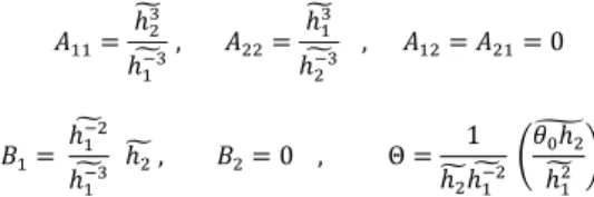
𝐴11= ℎ̃23 ℎ̃ , 𝐴1−3 22= ℎ̃13 ℎ̃ , 𝐴2−3 12= 𝐴21= 0 𝐵1= ℎ̃1−2 ℎ̃ ℎ1−3 2 ̃ , 𝐵2= 0 , Θ = 1 ℎ2 ̃ℎ̃ (1−2 𝜃̃0ℎ2 ℎ̃ ) 12
Where ⋅ ̃ represents the average operator. The homogenized Reynolds equation in that case is 𝜕 𝜕𝑥( 𝐴11 12𝜇 𝜕𝑝0 𝜕𝑥) + 𝜕 𝜕𝑦( 𝐴22 12𝜇 𝜕𝑝0 𝜕𝑦) = 𝑅Ω 2 𝜕Θ𝐵1 𝜕𝑥 + 𝜕Θℎ0 𝜕𝑡 (5)
Table 1 – Homogenized factors for transverse and longitudinal sinusoidal texturing Transverse Longitudinal ℎ_𝜖(𝑥, 𝑦, 𝑥𝜖, 𝑦𝜖) ℎ(𝑥, 𝑦) + ℎ𝑟sin(𝑥𝜖) ℎ(𝑥, 𝑦) + ℎ𝑟sin(𝑦𝜖) 𝐴11(𝑥, 𝑦) 2(ℎ(𝑥, 𝑦)2− ℎ𝑟2) 5 2 2 ℎ(𝑥, 𝑦)2+ ℎ𝑟2 ℎ(𝑥, 𝑦) 3+3 2ℎ(𝑥, 𝑦)ℎ𝑟2 𝐴22(𝑥, 𝑦) ℎ(𝑥, 𝑦)3+ 3 2ℎ(𝑥, 𝑦)ℎ𝑟2 2 (ℎ(𝑥, 𝑦)2− ℎ 𝑟 2)52 2 ℎ(𝑥, 𝑦)2+ ℎ𝑟2 𝐵1(𝑥, 𝑦) 2ℎ(𝑥, 𝑦)(ℎ(𝑥, 𝑦)2− ℎ 𝑟 2) 2ℎ(𝑥, 𝑦)2+ ℎ𝑟2 ℎ(𝑥, 𝑦)
In the case when only one surface is textured it is possible to simplify the problem to a stationary problem ([13]). The film height is also independent of which side is textured due to Reynolds hypothesis. In order to compute the mean pressure distribution the finite element method can be used ([5]). Moreover the problem can be written as a linear complementary problem ([4], [5]). The discretized problem can be written then
{ ℍ(𝐱) 𝐩̅ + ℚ 𝐫̅ = 𝐟f(𝐱)
𝐩̅T 𝐫̅ = 0 , 𝐩̅ ≥ 0 , 𝐫̅ ≥ 0 (6)
where 𝐩̅ represents the dimensionless discrete pressure vector and 𝐱 the shaft displacements vector.
The dimensionless pressure is obtained with the following formula: 𝑝̅ = 𝑝
12𝜇Ω (𝑅𝐶)2
The boundary conditions in this study are only the atmospheric value of pressure at the bearing edge. As there is no supply groove, the rotating frame is even easier to program for the bearing pressure computation because the fluid grid is moving. Depending of the choice of the cavitation model (Reynolds or JFO), the matrix ℚ can be either the identity matrix ([4]) or the mass conservation matrix ([5]). The matrix ℍ and the vector ff are expressed:
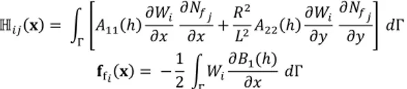
ℍ𝑖𝑗(𝐱) = ∫ [𝐴11(ℎ) 𝜕𝑊𝑖 𝜕𝑥 𝜕𝑁𝑓𝑗 𝜕𝑥 + 𝑅2 𝐿2𝐴22(ℎ) 𝜕𝑊𝑖 𝜕𝑦 𝜕𝑁𝑓𝑗 𝜕𝑦 ] Γ 𝑑Γ 𝐟f𝑖(𝐱) = −12 ∫ 𝑊𝑖 Γ 𝜕𝐵1(ℎ) 𝜕𝑥 𝑑Γ
𝑊𝑖 and 𝑁𝑓𝑗 state for the test function and the interpolation function of the finite
element method, respectively. However, the ℍ matrix and 𝐟f vector are non-linearly
dependent of the shaft position. For each new position of the journal the matrix coefficient must be computed with the integration of the flow factors. In order to compute efficiently the matrix ℍ(𝐱) and the vector ff(𝐱) for each time step of the
solver method, a polynomial development of the homogenized factor is used. The algorithm allows also the tilt of the shaft in the bearing. For example, one can write the average film height with a misaligned shaft in the pure squeeze rotating coordinates ([26]):
ℎ = 1 + 𝑒1𝑦 cos(2𝜋𝑥) + 𝑒2(1 − 𝑦)cos (2𝜋𝑥)
where 𝑒1 and 𝑒2 are the eccentricity of the two bearing edges.
Figure 1 – Homogenized pressure profile with sinusoidal longitudinal pattern with 𝒉𝒓= 𝟎. 𝟒 𝑪𝒓 with the bearing parameter of table 2 with tilted
shaft the relative eccentricity 𝒆𝟏= 𝟎. 𝟒, 𝒆𝟐= 𝟎. 𝟏
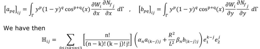
A polynomial approximation of 𝐴11(ℎ) at the order 3 is taken: 𝐴11(ℎ) = ∑3𝑛=0𝛼𝑛ℎ𝑛 and
𝐴22(ℎ) = ∑3𝑛=0𝛽𝑛ℎ𝑛.
From the trinomial expansion we obtain: (1 + 𝜖1𝑦 cos(𝑥) + 𝜖2(1 − 𝑦)cos (𝑥))n= ∑ [
n!
(n − k)! (k − j)! j!] 𝑒1𝑘−𝑗𝑦𝑘−𝑗𝑒2𝑗(1 − 𝑦)𝑗 cos𝑘(𝑥) 0≤𝑗≤𝑘≤𝑛
[𝑎𝑝𝑞]𝑖𝑗= ∫ 𝑦𝑝(1 − 𝑦)𝑞cosp+q(𝑥) 𝜕𝑊𝑖 𝜕𝑥 𝜕𝑁𝑓𝑗 𝜕𝑥 Γ 𝑑Γ , [𝑏𝑝𝑞]𝑖𝑗= ∫ 𝑦𝑝(1 − 𝑦)𝑞cosp+q(𝑥)𝜕𝑊𝑖 𝜕𝑦 𝜕𝑁𝑓𝑗 𝜕𝑦 Γ 𝑑Γ We have then ℍ𝑖𝑗= ∑ [ n! (n − k)! (k − j)! j!] (𝛼𝑛𝑎(𝑘−𝑗)𝑗+ 𝑅2 𝐿2𝛽𝑛𝑏(𝑘−𝑗)𝑗) 0≤𝑗≤𝑘≤𝑛≤3 𝑒1𝑘−𝑗𝑒 2𝑗
As the 10 matrices 𝑏𝑝𝑞 and 𝑑𝑝𝑞 are computed at the program initialization the
assembly of the matrix ℍ𝑖𝑗 is efficient. The same idea is easily applied to assemble
𝐟f.
Figure 2 - Polynomial interpolation of flow factors for transverse texturing pattern
3 A MONOLITHIC PROBLEM
3.1 A Rotordynamic system of a shaft on two bearings
The journal is modelled by a Timoshenko beam. A viscoelastic constitutive equation is taken ([27]):
𝜎 = 𝐸(𝜖 + 𝜂𝜖̇) (7) Where 𝜎 and 𝜖 are the main component of the stress tensor and the strain tensor in the beam neutral axis direction, respectively. Only the viscous damping is modelled, the hysteretic damping is taken equal to zero. The dynamic equation of a rotor with internal damping at constant rotating velocity is:
𝕄𝐱̈ + [𝕂𝑏+ Ω𝔾]𝐱̇ + [𝕂 + Ω𝕂𝑐]𝐱 = 𝐟d(Ω) + 𝐟s+ 𝐟b (8)
where 𝕄, 𝔾, 𝕂, 𝕂𝑏, 𝕂𝑐, 𝐟s, and 𝐟d, are the mass matrix, gyroscopic matrix, stiffness
matrix, structural damping matrix, circulatory matrix, static load force vector, and unbalance force vector, respectively. The gyroscopic matrix 𝔾 arises from the rotating movement of the Timoshenko beam. The circulatory matrix comes from the elastic deformation of the rotating beam with the viscoelastic law ([27]). With the constitutive law (7) the damping matrix is directly related to the stiffness matrix: 𝕂𝑏= 𝜂𝕂 . The discretised displacement vector 𝐱 is made of 4 degrees of
freedom per node ([27]). In order to project the fluid pressure on the structure one can express the virtual work of the bearings pressure on the shaft:
𝛿𝑊 = ∫ ∫ (cos(𝜃) 𝛿𝑢 + sin(𝜃) 𝛿𝑤)2 𝜋 0 𝑝 𝑅 𝑑𝜃 𝐿 0 𝑑𝑦 (9) As the inertia forces are neglected in Reynolds equation the choice of the pressure grid can be made in the rotating frame ([26]).
After discretization:
𝛿𝑊 = 𝛿𝐱Tℙ𝐩 (10)
The matrix ℙ is constructed directly from the fluid interpolation functions and the structure test functions.
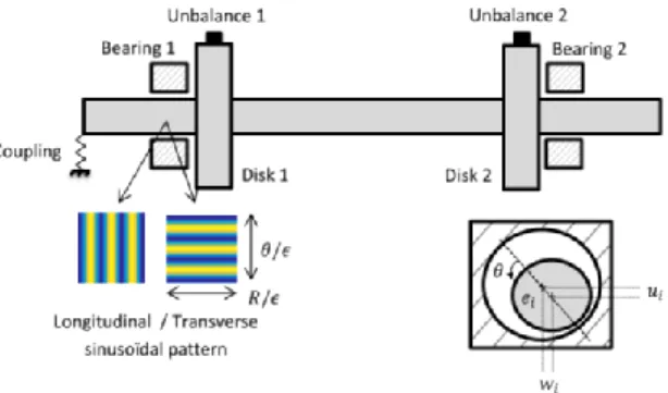
Figure 3 - Rotor - bearing system configuration
This allows taking into account the tilt of the shaft in the bearing. Hence, the dynamic system of equation of the system becomes
{ 𝕄𝐱̈ + [𝕂𝑏+ Ω𝔾]𝐱̇ + [𝕂 + Ω𝕂𝑐]𝐱 = 𝐟d(Ω) + 𝐟s+ ℙ𝐩̅ ℍ(𝐱) 𝐩̅ + ℚ 𝐫̅ = 𝐟f(𝐱) 𝐩̅T 𝐫̅ = 0 , 𝐩̅ ≥ 0 , 𝐫̅ ≥ 0 (11)
3.2 Application of the Harmonic Balance Method
The HBM consists in a search of solution of the form of a truncated Fourier series:
𝑥 = 𝑋0+ ∑ Xnccos(𝑛𝜔𝑡) + 𝑋𝑛𝑠sin (𝑛𝜔𝑡) 𝑁ℎ
𝑛=1
(12)
Introducing the following notations
𝑋 = [𝑋0 Xnc Xnc… Xnc XNhc]
𝑇
𝑇 = [𝐼 cos(𝜔𝑡) 𝐼 sin(𝜔𝑡) 𝐼 … cos(𝑛𝜔𝑡) 𝐼 sin(𝑛𝜔𝑡) 𝐼 ]𝑇
∇ = 𝑑𝑖𝑎𝑔(0𝑛×𝑛 ∇1… ∇Nh) with ∇k= 𝑘 [ 0 𝐼 −𝐼 0]
(13)
leads to the expression of the displacement, velocity and acceleration with the frequency domain unknowns vector:
𝑥 = 𝑇𝑋 𝑥̇ = 𝜔 𝑇𝛻𝑋 𝑥̈ = 𝜔𝑇𝛻2𝑋 (14)
By replacing these expressions in (11) and after a projection on the trigonometric functions basis one obtain a new nonlinear system without any time dependence:
(𝜔2𝑁
𝑀+ 𝜔𝑁𝐶+ 𝑁𝑘)𝑋 = 𝐹 + 𝐹𝑁𝐿(𝑋) (15)
with 𝑁𝑀= 𝑑𝑖𝑎𝑔(𝑀, … , 𝑀) a block diagonal matrix of 2𝑁ℎ+ 1 blocks, 𝑁𝐶 and 𝑁𝐾 are
The force F is composed by the static and dynamics load on their respective trigonometric projection.
The 𝐹𝑁𝐿 represents the non-linear projection in the frequency domain. To compute
this vector, the Alternate Frequency/Time domain has been used ([21]). From the frequency unknown vector 𝑋 , the position and velocity are constructed from equation (14). Then the fluid model allows us to compute the resulting force in the time domain from solving equation (8) and projecting the pressure with the projection matrix in (10). A Discrete Fourier Transform (DFT) of the resulting discrete time vector leads to the contribution of the non-linear force on each harmonic. This method can be resumed by the following scheme:
𝑋 → (𝑥, 𝑥̇) → 𝑓𝑛𝑙(Ω, 𝑥, 𝑥̇) → 𝐹𝑛𝑙(𝑋)
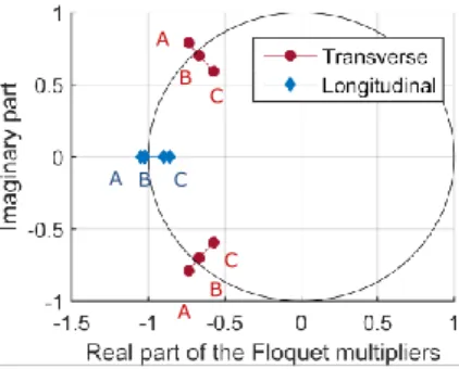
A basic Newton-Raphson algorithm is used to solve the system (15). Once the solution 𝑋 the system (15) is found the velocity and displacement in the time domain are reconstructed with equations (14). Then, a stability analysis is performed. There are many ways to perform such an analysis with the HBM ([28]). In this paper we used the exponentials method to compute the monodromy matrix. The Floquet multipliers, i.e. the eigenvalue of the monodromy matrix are then used to analyse stability of the synchronous motion. An unstable limit cycle is characterized by at one Floquet multiplier with a complex modulus greater than 1 ([29]).
Figure 4 - Neimark-Sacker and period-doubling bifurcation of limit cycles with shaft rotating speed variation for transverse texturing and period
doubling bifurcation for longitudinal texturing pattern 𝒉𝒓= 𝟎. 𝟓 𝑪𝒓
4 NON-LINEAR RESPONSE TO MASS UNBALANCE
For a given rotating speed one can consider the stability zone of the unbalance response. The parameters of the study are given in table 2. The only static load applied to the horizontal rotor is its weight. In that case a study of a perfectly balanced shaft leads to highly unstable motions. Van de Vorst et al. showed that for lightweight rotors the mass unbalance can achieve stability of the motion ([3]). Besides in the case where the cavitation pressure is sub-ambient, the full film lubrication can happen when the pressure is not low enough for the fluid to vaporize in the bearing. The Sommerfeld pressure profile is thus obtained and leads to highly unstable motions. Adding mass unbalance can solve the problem by forcing cavitation. Although the mass unbalance distribution stabilizes the system, it also increases the amplitude of stable vibration. The aim of this paper is to analyse the impact of surface texturing on the minimum mass unbalance to achieve stability. A C B C B A A B C 𝐹𝐹𝑇 𝑇
Table 2 - Rotor-bearing parameters
Shaft parameters Hydrodynamic bearings parameters
Radius 𝑅 = 2.5 𝑚𝑚 Bearing length 𝐿𝑝= 5 𝑚𝑚
Young Modulus 𝐸 = 211 𝐺𝑃𝑎 Radial clearance 𝐶𝑟= 10 𝜇𝑚
Poisson coefficient 𝜈 = 0.3 Oil viscosity 𝜇 = 0.002 𝑃𝑎. 𝑠 Density 𝜌𝑠= 7800 𝑘𝑔/𝑚3 Cavitation pressure 𝑝𝑐𝑎𝑣= − 1 𝑏𝑎𝑟
Shaft length 𝐿𝑎= 130 𝑚𝑚 Disks parameters
Internal damping coef. 𝜂 = 2.10−7 Density 𝜌
𝑑= 2700 𝑘𝑔/𝑚3
Coupling radial stiffness 8400 𝑁/𝑚 Radius 𝑅 = 7.5 𝑚𝑚 Coupling angular stiffness 0.014 𝑁/° Length 𝐿𝐷= 5 𝑚𝑚
Rotating velocity range 2.500 − 3.000 𝑟𝑎𝑑/𝑠 ~23.900 − 28.600 𝑟𝑝𝑚
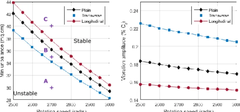
We also focus on the minimum stable vibration amplitude that can be obtained with a certain texturing pattern. Numerical integration shows that the Neimark-Sacker and the flip bifurcation point seem to be subcritical. The minimum mass unbalance to achieve stability for a certain shaft rotating velocity is plotted on the figure 5. For computational time purpose, the Reynolds cavitation hypothesis has been used to solve Reynolds equation in that example. A straightforward dichotomy method has been used to find the Neimark-Sacker bifurcation point.
The computation of Floquet multipliers shows that varying the mass unbalance parameter give rise to a generalized Hopf bifurcation or Neimark-Sacker bifurcation (figure 4) in the case of sinusoidal transverse texturing. In the case of sinusoidal longitudinal texturing as well as for plain bearings the parameters of the study give rise to a flip bifurcation.
Figure 5 - Minimum mass unbalance for stable motion and vibration amplitude of the corresponding boundary stable system 𝒉𝒓= 𝟎. 𝟓 𝑪𝒓 for each
rotating speed
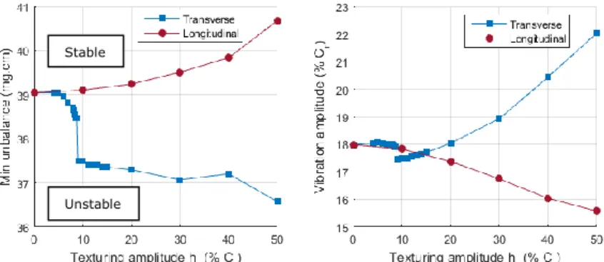
For both systems the minimum unbalance decreases while the rotating speed increases. This means that the system can be unstable during the start-up and stabilise himself after a certain threshold speed. On the diagram we can notice that the minimum unbalance mass is slightly lower for transverse texturing. For example at 2500 rad/s the mass unbalance needed to stabilize the system with sinusoidal transverse texturing (hr = 0.5) is 10% lower than with the sinusoidal longitudinal texturing (hr = 0.5). However, if we pay attention to the vibration amplitude obtained with the boundary stable system we notice that the amplitude value with transverse texturing is 30% higher than with longitudinal texturing. Figure 6 shows the vibration amplitude with the limit unbalance for stable motion, for different amplitude of sinusoidal texturing patterns. The shaft rotating speed is 2500 rad/s for all the simulation points. The diagram clearly shows the decrease of
Unstable Stable A + C + B +
vibration amplitude with longitudinal texturing patterns, while with transverse texturing patterns it significantly increases for ℎ𝑟≥ 0.1 𝐶𝑟 . Below this value we
notice a significant variation of the minimum unbalance. For transverse sinusoidal texturing pattern with ℎ𝑟≈ 0.1 𝐶𝑟 , both the decrease of the minimum unbalance and
the vibration amplitude are achieved.
Figure 6 – Vibration amplitude as a function of texturing pattern amplitude for transverse and longitudinal sinusoidal texturing at 2500 rad/s
5 CONCLUSIONS
This study is focused on the impact of textured bearing on small rotating shafts vibration. We have presented a powerful method to study the stability of the unbalance response on the system based on multi-scale homogenization of Reynolds equation. The monolithic resolution of the coupled system of equation is performed. The harmonic balance method gives fast and accurate results to study unbalance response and stability of limit cycles.
We noticed that transverse texturing patterns lower the minimum mass unbalance needed for stability although it increases the vibration amplitude. On the opposite the longitudinal texturing pattern allows substantial reduction of the vibration amplitude. However it increases the minimum unbalance needed for stable motion. This study has been performed for one dimensional sinusoidal texturing of finite bearing. However, homogenized flow factor for arbitrary textured bearing could be computed and approximated by polynomials separately and added to the algorithm. Furthermore, the algorithm can be adapted for the averaged flow factors of De Kraker ([15]) to take into account recirculation of lubricant in the asperities.
BIBLIOGRAPHY
[1] J. W. Lund, “Review of the Concept of Dynamic Coefficients for Fluid Film Journal Bearings,” J. Tribol., vol. 109, no. 1, pp. 37–41, Jan. 1987.
[2] C. J. Myers, “Bifurcation Theory Applied to Oil Whirl in Plain Cylindrical Journal Bearings,”
J. Appl. Mech., vol. 51, no. 2, pp. 244–250, Jun. 1984.
[3] E. L. B. V. D. Vorst, R. H. B. Fey, A. D. Kraker, and D. H. V. Campen, “Steady-state behaviour of flexible rotordynamic systems with oil journal bearings,” Nonlinear Dyn., vol. 11, no. 3, pp. 295–313, Nov. 1996.
[4] T. Zheng and N. Hasebe, “Nonlinear Dynamic Behaviors of a Complex Rotor-Bearing System,” J. Appl. Mech., vol. 67, no. 3, pp. 485–495, Nov. 1999.
[5] M. Giacopini, M. T. Fowell, D. Dini, and A. Strozzi, “A Mass-Conserving Complementarity Formulation to Study Lubricant Films in the Presence of Cavitation,” J. Tribol., vol. 132, no. 4, pp. 041702–041702, Sep. 2010.
[6] I. Etsion, “State of the Art in Laser Surface Texturing,” J. Tribol., vol. 127, no. 1, p. 248, 2005.
Unstable Stable
[7] D. B. Hamilton, J. A. Walowit, and C. M. Allen, “A Theory of Lubrication by Microirregularities,” J. Basic Eng., vol. 88, no. 1, pp. 177–185, Mar. 1966.
[8] S. T. Tzeng and E. Saibel, “Surface Roughness Effect on Slider Bearing Lubrication,” E
Trans., vol. 10, no. 3, pp. 334–348, Jan. 1967.
[9] N. Patir and H. S. Cheng, “An Average Flow Model for Determining Effects of Three-Dimensional Roughness on Partial Hydrodynamic Lubrication,” J. Tribol., vol. 100, no. 1, pp. 12–17, Jan. 1978.
[10] H. G. Elrod, “A General Theory for Laminar Lubrication With Reynolds Roughness,” J.
Tribol., vol. 101, no. 1, pp. 8–14, Jan. 1979.
[11] G. Bayada and J. B. Faure, “A Double Scale Analysis Approach of the Reynolds Roughness Comments and Application to the Journal Bearing,” J. Tribol., vol. 111, no. 2, pp. 323– 330, Apr. 1989.
[12] G. Bayada, S. Martin, and C. Vázquez, “An Average Flow Model of the Reynolds
Roughness Including a Mass-Flow Preserving Cavitation Model,” J. Tribol., vol. 127, no. 4, pp. 793–802, May 2005.
[13] A. Almqvist, E. K. Essel, L.-E. Persson, and P. Wall, “Homogenization of the unstationary incompressible Reynolds equation,” Tribol. Int., vol. 40, no. 9, pp. 1344–1350, Sep. 2007. [14] A. Almqvist, J. Fabricius, and P. Wall, “Homogenization of a Reynolds equation describing
compressible flow,” J. Math. Anal. Appl., vol. 390, no. 2, pp. 456–471, 2012.
[15] A. de Kraker, R. A. J. van Ostayen, and D. J. Rixen, “Development of a texture averaged Reynolds equation,” Tribol. Int., vol. 43, no. 11, pp. 2100–2109, Nov. 2010.
[16] N. Tala-Ighil, M. Fillon, and P. Maspeyrot, “Effect of textured area on the performances of a hydrodynamic journal bearing,” Tribol. Int., vol. 44, no. 3, pp. 211–219, Mar. 2011. [17] V. Brizmer and Y. Kligerman, “A Laser Surface Textured Journal Bearing,” J. Tribol., vol.
134, no. 3, pp. 031702–031702, Jun. 2012.
[18] J. Ramesh and B. C. Majumdar, “Stability of Rough Journal Bearings Using Nonlinear Transient Method,” J. Tribol., vol. 117, no. 4, pp. 691–695, Oct. 1995.
[19] R. Turaga, A. S. Sekhar, and B. C. Majumdar, “Non-Linear Transient Stability Analysis of a Rigid Rotor Supported on Hydrodynamic Journal Bearings with Rough Surfaces,” Tribol.
Trans., vol. 43, no. 3, pp. 447–452, Jan. 2000.
[20] J.-R. Lin, “Application of the Hopf bifurcation theory to limit cycle prediction of short journal bearings with isotropic roughness effects,” Proc. Inst. Mech. Eng. Part J J. Eng.
Tribol., vol. 221, no. 8, pp. 869–879, 2007.
[21] T. M. Cameron and J. H. Griffin, “An Alternating Frequency/Time Domain Method for Calculating the Steady-State Response of Nonlinear Dynamic Systems,” J. Appl. Mech., vol. 56, no. 1, pp. 149–154, Mar. 1989.
[22] E. Sarrouy and F. Thouverez, “Global search of non-linear systems periodic solutions: A rotordynamics application,” Mech. Syst. Signal Process., vol. 24, no. 6, pp. 1799–1813, Aug. 2010.
[23] A. Grolet and F. Thouverez, “Computing multiple periodic solutions of nonlinear vibration problems using the harmonic balance method and Groebner bases,” Mech. Syst. Signal
Process., vol. 52–53, pp. 529–547, Feb. 2015.
[24] S. Nacivet, C. Pierre, F. Thouverez, and L. Jezequel, “A dynamic Lagrangian frequency– time method for the vibration of dry-friction-damped systems,” J. Sound Vib., vol. 265, no. 1, pp. 201–219, Jul. 2003.
[25] H. G. Elrod, “A Cavitation Algorithm,” J. Tribol., vol. 103, no. 3, pp. 350–354, Jul. 1981. [26] D. Childs, H. Moes, and H. van Leeuwen, “Journal Bearing Impedance Descriptions for
Rotordynamic Applications,” J. Lubr. Technol., vol. 99, no. 2, pp. 198–210, Apr. 1977. [27] E. S. Zorzi and H. D. Nelson, “Finite Element Simulation of Rotor-Bearing Systems With
Internal Damping,” J. Eng. Power, vol. 99, no. 1, pp. 71–76, Jan. 1977.
[28] L. Peletan, S. Baguet, M. Torkhani, and G. Jacquet-Richardet, “A comparison of stability computational methods for periodic solution of nonlinear problems with application to rotordynamics,” Nonlinear Dyn., vol. 72, no. 3, pp. 671–682, Jan. 2013.
[29] A. H. Nayfeh, Applied nonlinear dynamics: analytical, computational, and experimental