HAL Id: tel-02418445
https://hal.inria.fr/tel-02418445v2
Submitted on 25 Jun 2020HAL is a multi-disciplinary open access archive for the deposit and dissemination of sci-entific research documents, whether they are pub-lished or not. The documents may come from teaching and research institutions in France or abroad, or from public or private research centers.
L’archive ouverte pluridisciplinaire HAL, est destinée au dépôt et à la diffusion de documents scientifiques de niveau recherche, publiés ou non, émanant des établissements d’enseignement et de recherche français ou étrangers, des laboratoires publics ou privés.
Valentin Deschaintre
To cite this version:
Valentin Deschaintre. Lightweight material acquisition using deep learning. Image Processing [eess.IV]. COMUE Université Côte d’Azur (2015 - 2019), 2019. English. �NNT : 2019AZUR4078�. �tel-02418445v2�
profond
Valentin Deschaintre
Inria Sophia Antipolis-M´editerann´ee, Optis an Ansys affiliate
Pr´esent´ee en vue de l’obtention du grade de docteur en Informatique d’Universit´e Cˆote d’Azur
Dirig´ee par : Adrien Bousseau, George Drettakis
Soutenue le : 25 Novembre 2019
Devant le jury compos´e de :
Pr. Holly Rushmeier, Professor, Yale University Pr. Niloy Mitra, Professor, University College London
Pr. Matthias Nießner, Professor, Technical Univer-sity of Munich
Pr. Xavier Granier, Professeur, Institut d’Optique Dr. Abhijeet Ghosh, Associate Professor, Imperial College London
Dr. Adrien Bousseau, Charg´e de Recherche, Univer-sit´e Cˆote d’Azur, Inria
Dr. George Drettakis, Directeur de Recherche, Universit´e Cˆote d’Azur, Inria
Dr. Anthony Jouanin, Hardware & Measure man-ager, Ansys
profond
Lightweight material acquisition using deep
learning
Jury:
Pr´esident du jury / President of the jury Pr. Holly Rushmeier, Professor, Yale University Rapporteurs / Reviewers
Pr. Holly Rushmeier, Professor, Yale University Pr. Niloy Mitra, Professor, University College London Examinateurs / Examiners
Pr. Matthias Nießner, Professor, Technical University of Munich Pr. Xavier Granier, Professeur, Institut d’Optique
Dr. Abhijeet Ghosh, Associate Professor, Imperial College London Invit´es / Invited
Dr. Anthony Jouanin, Hardware & Measure manager, Ansys Dr. Vincent Hourdin, Research engineer, Ansys
Directeurs de th`ese / Thesis supervisors
Dr. Adrien Bousseau, Charg´e de Recherche, Universit´e Cˆote d’Azur, Inria Dr. George Drettakis, Directeur de Recherche, Universit´e Cˆote d’Azur, Inria
I would first like to express how grateful I am to my family for encouraging me to be curious and expanding my horizon throughout my youth. It is the support and education you provided me that made this whole adventure possible.
Of course, I would like to deeply thank Adrien Bousseau and George Drettakis, my advi-sors, for their support, encouragements and guidance during my PhD. I am also grateful to you for the freedom to explore the directions I was curious about, for introducing me into an incredible community and for the opportunities you made possible that I would never have hoped for.
One of these opportunities was to collaborate with MIT, and I thank Fredo Durand and his whole group very much for welcoming me during my visits there!
My thesis was funded through the French CIFRE system and I am grateful to Optis, Inria and ANRT for making this possible. Especially Vincent Hourdin for being there for me from the first moment I drafted the idea of this thesis and Anthony Jouanin for supervising the industrial aspect of my work.
But these years would have been lonely if not for the Graphdeco group members, I thank you all for our debates and laughs during lunches, coffee breaks and events, the technical discussions and philosophical research conversations.
In particular, I would like to mention Simon Rodriguez with whom I shared not only the office but also the ups and downs inherent to research, and many jokes! I also thank Yulia Gryaditskaya very much for her support, her kindness and our discussions which helped me to better understand the academic world and encouraged me to explore it further. I am also grateful to Miika Aittala for his help in building my knowledge, for teaching me some Finnish, but most importantly for our never ending chats around MIT’s couches. I met too many great people during these years to list exhaustively, but if we exchanged ideas, had dinner, drank a beer or simply shared tea, these acknowledgements are also meant for you!
Que ce soit pour le divertissement ou le design industriel, l’infographie est de plus en plus pr´esente dans notre vie quotidienne. Cependant, reproduire une sc`ene r´eelle dans un environnement virtuel reste une tˆache complexe, n´ecessitant de nombreuses heures de travail. L’acquisition de g´eom´etries et de mat´eriaux `a partir d’exemples r´eels est une solution, mais c’est souvent au prix de processus d’acquisitions et de calibrations com-plexes. Dans cette th`ese, nous nous concentrons sur la capture l´eg`ere de mat´eriaux afin de simplifier et d’acc´el´erer le processus d’acquisition et de r´esoudre les d´efis industriels tels que la calibration des r´esultats. Les textures et les ombres sont quelques-uns des nombreux indices visuels qui permettent aux humains de comprendre l’apparence d’un mat´eriau `a partir d’une seule image. La conception d’algorithmes capables de tirer parti de ces indices pour r´ecup´erer des fonctions de distribution de r´eflectance bidirection-nelles (SVBRDF) variant dans l’espace `a partir de quelques images pose un d´efi aux cher-cheurs en infographie depuis des d´ecennies. Nous explorons l’utilisation de l’apprentis-sage profond pour la capture l´eg`ere de mat´eriaux et analyser ces indices visuels. Une fois entraˆın´es, nos r´eseaux sont capables d’´evaluer, par pixel, les normales, les albedos dif-fus et sp´eculaires et une rugosit´e `a partir d’une seule image d’une surface plane ´eclair´ee par l’environnement ou un flash tenu `a la main. Nous montrons ´egalement comment notre m´ethode am´eliore ses pr´edictions avec le nombre d’images en entr´ee et permet des reconstructions de haute qualit´e en utilisant jusqu’`a 10 images d’entr´ees — un bon compromis entre les approches existantes.
Whether it is used for entertainment or industrial design, computer graphics is ever more present in our everyday life. Yet, reproducing a real scene appearance in a virtual envi-ronment remains a challenging task, requiring long hours from trained artists. A good solution is the acquisition of geometries and materials directly from real world examples, but this often comes at the cost of complex hardware and calibration processes. In this thesis, we focus on lightweight material appearance capture to simplify and accelerate the acquisition process and solve industrial challenges such as result image resolution or calibration. Texture, highlights, and shading are some of many visual cues that al-low humans to perceive material appearance in pictures. Designing algorithms able to leverage these cues to recover spatially-varying bi-directional reflectance distribution functions (SVBRDFs) from a few images has challenged computer graphics researchers for decades. We explore the use of deep learning to tackle lightweight appearance cap-ture and make sense of these visual cues. Once trained, our networks are capable of recovering per-pixel normals, diffuse albedo, specular albedo and specular roughness from as little as one picture of a flat surface lit by the environment or a hand-held flash. We show how our method improves its prediction with the number of input pictures to reach high quality reconstructions with up to 10 images — a sweet spot between existing single-image and complex multi-image approaches — and allows to capture large scale, HD materials. We achieve this goal by introducing several innovations on training data acquisition and network design, bringing clear improvement over the state of the art for lightweight material capture.
Contents vii
1 Introduction 1
1.1 Motivation . . . 1
1.2 Challenges and contributions . . . 4
1.3 Thesis Context . . . 7
2 Related Work 9 2.1 Materials and rendering . . . 9
2.2 Deep learning . . . 17
2.3 Deep learning for material acquisition . . . 23
3 Single-Image SVBRDF Capture with a Rendering-Aware Deep Network 29 3.1 Network Architecture . . . 30
3.2 Procedural Synthesis of Training Data . . . 39
3.3 Evaluation . . . 45
3.4 Conclusion . . . 53
4 Flexible SVBRDF Capture with a Multi-Image Deep Network 57 4.1 Capture Setup . . . 59
4.2 Multi-Image Material Inference . . . 59
4.3 Online Generation of Training Data . . . 62
4.4 Results and Evaluation . . . 63
4.5 Conclusion . . . 76
5 By-Example Capture of Large-Scale SVBRDFs 77 5.1 Method . . . 79
5.2 Evaluation . . . 83
5.3 Conclusion . . . 92
6 Industrial challenges 93 6.1 Research transfer . . . 93
6.2 Evaluation against gonioreflectometer . . . 97
7 Conclusion 105 7.1 Future work . . . 107
A Appendix 111 A.1 Rendering loss pseudo-code . . . 111
Introduction
In this section I provide a brief introduction to the topic of this thesis, I then summarize the main challenges and our key contributions. I conclude this chapter with the overview of how the research conducted over my PhD is supplemented with a contribution to industrial challenges.
1.1
Motivation
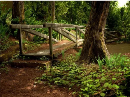
Photo-realism has been pursued in Computer Graphics for decades. With better algo-rithms and more computing power, it is now possible to render scenes that are virtually impossible to distinguish from a photograph (Figure1.1).
Nevertheless, creating realistic virtual scenes or characters takes hours for trained artists. We ask the following questions in this thesis, and attempt to provide first answers: can we facilitate this process? Can we provide the tools which would allow non-expert users to create their own virtual content?
In this thesis we make an important step towards achieving this goal. We build on the idea that real scenes are a rich source of information that can be exploited for virtual scene creation. This will not only reduce the workload in the movie and games indus-tries, but also facilitate every-day use of virtual content. For instance, one might be interested in recreating their living space in order to experiment with lighting, wallpa-pers, furniture, other design elements, or integrate familiar elements in larger scenes. Real scene reproduction in a virtual environment is one of the big challenges at the intersection between computer vision and computer graphics. To ensure an immersive and convincing experience, the appearance of a scene has to be re-created accurately. This is a challenging task, as the appearance of real-world objects results from complex interactions between light, material reflectance, and geometry. While scene geometry can be obtained with techniques such as multiview stereo algorithms or depth scanners, recovering a numerical representation of materials from photographs or measurements
Figure 1.1: A photo-realistic rendering which won the 2012 blenderGuru Photorealism Competition.Author: Major4z
of a surface is at the heart of appearance capture algorithms, that is the focus of this thesis.
The visual appearance and an accurate physical representation of materials are impor-tant in multiple industries. In industrial design, for example, it reduces the need for physical prototypes by allowing to quickly and efficiently test different appearances and to observe materials behavior under different lighting conditions. For instance, accurate reproduction of materials is crucial for the car industry, where reflectance properties of the materials have to be carefully taken into consideration before production (as illus-trated in Figure1.2).
Virtual content is also widely used in movie making, since it not only allows to create entirely virtual environment, but also to reduce the shooting costs in difficult environ-ments, or conditions in terms of teams and equipment. Furthermore, it allows to create multiple versions of the content and facilitates its editing. Figure1.3illustrates how such techniques are used in recent movies. Visually consistent integration of characters, ob-jects and visual effects is key to engaging users and maintaining their attention. This cannot be achieved without convincing material appearance.
Figure 1.2: An example of virtual prototyping with Ansys software. Image source: www.3dprintingmedia.network
Figure 1.3: The top part shows the scene capture by cameras, in contrast with the bottom part, showing the addition of Godzilla and the bridge.Image credit: Godzilla, ©Warner Bros, 2014
1.2
Challenges and contributions
Traditionally, accurate material appearance capture requires dense sampling of light and view directions in a controlled acquisition enviroment [SSW+14, XNY+16]. Such an
approach has been used in production for movie making for example. Expensive light stages based on the design by Debevec et al. [DHT+00] were used for movies like Avatar
(2009) or Superman Returns (2006).
Such advanced capture setups are needed because many different reflectances, geome-tries or lighting can yield the same observed image. For example, any single photograph can be reproduced by a diffuse albedo map, where highlights are “painted” over the surface. Nevertheless, even given a single image, human observers can immediately understand the material in many cases thanks to our prior knowledge.
Designing a priori assumptions about the space of plausible material solutions to guide simpler acquisition processes has challenged researchers for decades [GGG+16].
Re-cently, Deep Learning has emerged as a powerful method to automatically learn effective priors from data.
In this thesis, we focus on the challenges of lightweight material capture and propose supervised deep learning approaches. We train neural networks to solve the ill-posed inverse problem of estimating a spatially-varying bi-directional reflectance distribution function (SVBRDF) from a limited number of pictures. SVBRDFs represent the behavior of materials, depending on the incoming light and the view direction. We use the Cook-Torrance [CT82] analytical material model, allowing to represent each pixel of a SVBRDF with just a few parameters. We chose this model for its capacity to represent many classes of materials and its wide use in industry.
To achieve high performance with Deep Learning approaches, one has to build a tailored network architecture and loss function. Moreover, supervised learning requires a large amount of representative training data. Acquiring such data is a common challenge of deep-learning based approaches. I summarize below our solutions to these challenges and detail them in the following chapters.
Architecture design
The task of our deep networks is to predict four maps corresponding to per-pixel Cook-Torrance [CT82] parameters representing the material appearance. Importantly, this model distinguishes the Diffuse albedo, representing the light that is reflected in all di-rections by the material, and the Specular albedo, representing the light reflected around the mirror direction.
In this thesis I present a number of novel algorithms allowing the capture of a plausible material representation using different lightweight acquisition setups. Our algorithms adapt to the available input, whether it is a single flash picture, multiple ones, or a large scale image.
Single-image acquisition. In Chapter3 we propose an algorithm that requires one single near-field flash-lit photograph as input. Flash photographs are easy to acquire, and have been shown to contain a lot of information that can be leveraged in inferring the material properties from one [AP07, AWL15, AAL16] or multiple images [RPG16,
HSL+17]. In such images, the pixels showing the highlight provide strong cues about specularity, whereas the outer pixels show diffuse and normal variations more promi-nently. To arrive at a consistent solution across the image, these regions need to share information about their respective observations.
Our experiments reveal that existing deep learning architectures struggle to aggregate distant information in an image. To address this limitation, we develop a secondary network that extracts global features and propagates it through the main network, fa-cilitating back-and-forth exchange of information across distant image regions.
Multiple-image acquisition. Our methods allow to retrieve a SVBRDF representa-tion from just a single flash picture, but in many cases a single photograph simply does not contain enough information to completely acquire a material. In Chapter4, we pro-pose a method that is capable of aggregating the cues provided by additional pictures, while retaining a lightweight capture procedure. With this method, we are able to im-prove the results with more pictures until the user is satisfied with the result. We discuss both the quantitative and qualitative improvement of the results as they get closer to ground truth with more inputs photographs.
Acquisition scale, user control and high resolution. The solutions proposed in Chapters3 and4 —and concurrent work [LSC18, GLD+19] are nonetheless limited in terms of resolution, scale of acquisition and user control. Indeed, near-field flash light-ing greatly restricts the scale at which materials can be captured – typically around twenty centimeters wide using a cell phone held at a similar distance. Another common limitation of the above methods is that they rely on black-box optimization or deep learn-ing to infer SVBRDF parameters from few measurements, offerlearn-ing little user control on their output. We address these two challenges in Chapter5by proposing a by-example, multi-scale appearance capture method, which recovers SVBRDF parameter maps over large-scale environmentally lit surfaces by propagating information from a few small-scale exemplar SVBRDF patches.
An added benefit of using environmental lighting is that we can split the large-scale image into smaller tiles processed independently by our deep network, using the same exemplars to promote coherence. This mechanism allows us to treat high-resolution images as collections of tiles that we stitch seamlessly in a post-process, resulting in SVBRDF maps of up to 4K pixels wide. In contrast, existing deep learning methods need to process the input images in their entirety to exploit the complementary visual cues given by the spatially-varying flash lighting, which limits these methods to small resolutions to fit in GPU memory [DAD+18,LSC18,DAD+19,GLD+19].
Through our work, we show that our deep learning based SVBRDF acquisition methods are able to produce convincing results for complex spatially varying materials made from multiple elements.
Data generation
To predict material models, we use supervised learning, which comes with the challenge of finding enough training data. We solve the lack of large real-world material datasets by leveraging artist-created, procedural SVBRDFs [All19b], which we sample and render under multiple lighting directions to create training images. We further augment the data by randomly mixing these SVBRDFs together (Chapter3) and introducing an in-line rendering pipein-line (Chapter4), allowing for virtually infinite material variation.
Loss design
To train a network a suitable loss function must be defined, which evaluates the quality of the output model parameters against the ground truth. A naive optimization function (loss) would be to directly minimize the pixel-wise difference between predicted and ground truth material model. But this approach is suboptimal, as it does not consider the interactions between the different material parameter maps. Intuitively, while a pre-dicted map may look plausible when observed in isolation, it may yield an image far from the ground truth when combined with the other parameter maps when evaluating the BRDF function.
Furthermore, the numerical differences in the parameter maps might not consistently correlate with differences in the material’s appearance, causing the naive loss to weight the importance of different features arbitrarily. We mitigate these shortcomings by for-mulating a differentiable SVBRDF similarity metric that compares the renderings of the predicted maps against renderings of the ground truth from several lighting and viewing directions.
1.3
Thesis Context
This thesis was funded by a CIFRE (Academic/Industrial) collaboration between the French government (ANRT), Inria and Optis, an ANSYS affiliate. We therefore took in-dustrial challenges into account during the definition of our research axes. We describe the experiments we conducted to address some of these challenges, while respecting the required industrial confidentiality.
Optis is a software development company specialized in physics based lighting simula-tion. More specifically, Optis proposes solutions for optical simulation, physics-based rendering, virtual reality and physics-based sensor simulation for industry. This allows engineers and artists to prototype in a virtual environment and quickly iterate to not only improve visual design, but also the assembly process, potential visual discomfort or usability. This process limits the need for costly physical prototypes and reduces de-velopment time.
To physically simulate light behavior, Optis identified a need in accurately measuring materials. The Hardware & Measure team is responsible for the evolution of the two Gonioreflectometers developed at Optis. The OMS2 is portable and capable of measuring
a BRDF in around a minute, while the OMS4 measure bench focuses on higher precision and volumetric measurements. Both devices only provide one BRDF per material and do not measure their spatial variations.
With lightweight acquisition, this thesis complements Optis’ expertise in material acqui-sition. Our results simplify the process for artists to evaluate multiple materials during the design phase or to recreate a familiar environment. With this, the heavy and long measurement with specialized tools can be postponed to a phase where the product is better defined.
In addition, my responsibilities during this thesis included knowledge transfer and adap-tation of the academic research to industrial needs. In Chapter6, I describe some of the work done to answer to some of the issues encountered, such as inferring a different material model or evaluating our method against real measurements.
Finally, in the conclusion of this thesis, I discuss our methods, results and provide inter-esting directions to explore for future work.
Related Work
2.1
Materials and rendering
2.1.1 Rendering
The goal of a rendering pipeline is to simulate the appearance of a 3D scene, given in-formation about camera positions, scene geometry, surface materials and lighting con-ditions. For the purpose of this thesis, I focus on realistic rendering systems aiming to reproduce real world appearance. A rendering is obtained by simulating light interaction with objects in a 3D environment, as defined by the rendering equation [Kaj86]:
Lo(x, ωo, λ, t) = Le(x, ωo, λ, t) +
R
ωfr(x, ωi, ωo, λ, t)Li(x, ωi, λ, t)(ωi· n)dωi
Lorepresents the radiance depending on the wavelengthλ, the location in space x, the
outgoing light directionωoand timet. Ledefines the emitted radiance, while the integral
overω represents the interaction between the surface material and the incoming light contributions over the hemisphere centered around the normaln to the surface. More specifically, fr represents the material reflective properties, function of the incoming
light direction ωi, ωo, x, t and λ . Li represents the incoming light as a function of
positionx, ωi,t and λ. Finally (ωi· n) represents the attenuation factor of influence of a
light source due to incident angle. Intuitively, this equation represents how the occlusion of light, orientation and distance of different objects drives the shading and how the different materials in the scene drive light reflection, refraction or transmission. Multiple rendering methods simulate the light behavior with various degrees of accuracy and computational power required to produce a frame. This thesis focuses on the acquisition of the material reflective propertiesfrfrom few images.
2.1.2 Materials
During the rendering process, light interacts with different surfaces, each made of dif-ferent materials. For each interaction, the renderer needs to resolve which part of the
Figure 2.1: Light effects represented by a BRDF and a BTDF. The BRDF represents the reflected part of light, while the BTDF represents the transmitted part.Credit: Wikipedia User:Jurohi
light is absorbed, transmitted and reflected. Bartel et al. [FEW81] define the Bidirectional scattering distribution function (BSDF) to represent both the transmittance (BTDF) and the reflectance (BRDF) of a material —frin Kajiya rendering equation— , see Figure2.1.
2.1.3 Material representation
In this thesis we focus on the reflection and absorption properties of materials. The most common representation is the Bidirectional Reflectance Distribution Function (BRDF) which defines for each incident lighting angle (θi,φi) and outgoing view angle (θo,φo)
the amount of energy that is absorbed or reflected for each considered wavelengthλ. The BRDF is an approximation of the Bidirectional Subsurface Scattering Reflectance Distri-bution Function (BSSRDF) described by Nicodemus et al. [NRH+77]. With a BRDF, it
is assumed that all light enters and leave from the same point, while BSSRDFs allow to model light behavior below material surfaces -such as in human skin. The Spatially
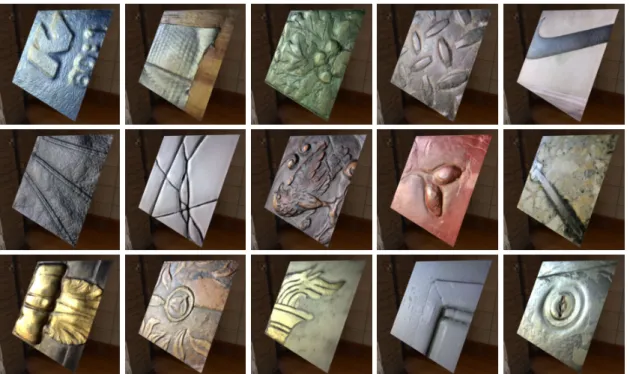
Figure 2.2: Examples of SVBRDFs rendered using a parametric model and a virtual en-vironment.
Varying BRDF (SVBRDF) adds two spatial dimensions, allowing to define maps of vary-ing appearance (e.g. for multi-material objects). Figure2.2shows renderings generated using SVBRDFs and a virtual environment.
A different approach to material appearance representation was introduced by Dana et al. [DVGNK99] in the form of Bidirectional Texture Function (BTF). This represen-tation consists of hundreds to thousands of different pictures of a texture from differ-ent light/view angle. The rendering process samples for each differdiffer-ent pixel the closest view/light configurations available in the pictures, matching the rendering condition. Unlike the BRDF, this representation includes meso-structures —small geometric de-tails on the surface—, shading, sub-surface scattering, cast shadows and other subtle effects visible on the material as they are present in the acquired pictures. This cap-ture of a wide variety of effects comes with the cost of a complex acquisition setup -see Figure2.3), a challenging interpolation between pictures for novel views and a signif-icant amount of data for each material. This representation is therefore not suited for our lightweight acquisition problematic. Nevertheless, these challenges are addressed
Figure 2.3: The Dome II, a BTF acquisition device developped by the University of Bonn [SSW+14].
in work such as Rainer et al. [RJGW19], Wu et al. [WDR11], Havran et al. [HFM10] or Ruiters et al. [RK09].
While we use BTFs for comparison and evaluation of our work, our main material rep-resentation in this thesis are SVBRDF.
2.1.4 Material models
Measured BRDFs are usually acquired in a tabulated representation. The percentage of reflected light is stored for each θi, φi, θo, φo and wavelength λ. This results in
pre-cise depiction of material interaction with light, but leads to large amounts of data and therefore limits the edition possibilities —as five dimensional arrays can prove difficult to navigate. For more compact representations, material models approximate real world
material behavior using mathematical functions. These models are separated in two main categories, empirical -also called phenomenological- and physically-based models. The empirical models represent the appearance of a material with arbitrary parameters; they do not rely on the underlying physics of light behavior. Empirical material models include Phong [Pho75] or Ward [War92] for example. The Phong model uses 3 param-eters: diffuse, specular power and specular exponent. It is a simple model allowing to efficiently compute the appearance of simple diffuse or specular materials. As an empir-ical model it does not aim at physempir-ical realism, for example, it does not respect energy conservation and reciprocity. In 1992, the Ward [War92] model was proposed to be an intermediate between theoretical models, too complex to efficiently render, and fully empirical model such as Phong [Pho75]. The proposed model is ”physically plausible”, satisfying energy conservation at most angles and reciprocity, while still being based on empirical data.
On the opposite end of the spectrum, physically based models attempt to derive a mean-ingful set of parameters from physical theory. Examples of such models are Beckmann [BS87], Torrance-Sparrow [TS67] or Cook-Torrance [CT82]. The Beckmann model is based on electromagnetic laws and rough surface modelling. On the other hand the Torrance-Sparrow and Cook-Torrance are base on geometric optics and use a micro-facets surface model. Each surface is composed of microscopic surfaces, oriented with respect to the general surface normal. The orientations are defined by a probability dis-tribution function, varying between the different methods. In our work, we use the GGX distribution[WMLT07] of the Cook-Torrance model.
The GGX model is driven by three parameters. The first and second are diffuse and specular albedos which control the color and intensity of the light of the diffuse and specular behaviors at the interface with the material. The third is the roughness, which defines how glossy a material is by acting on the micro-facets orientation distribution. Examples of materials parametrized with this model and their renderings is available in Figure2.4. The exact equations we use in this thesis are described in the form of pseudo-code in AppendixA.1. Figure2.4shows examples of parameter maps and their associated renderings.
More details on the many different material representations and models are discussed in the extensive survey by Guarnera et al. [GGG+16].
Renderings Normal Diffuse Roughness Specular
Figure 2.4: Materials represented by their parametrization in the GGX [WMLT07] model and the associated renderings. More details on the meaning of parameters are available in section2.1.4.
2.1.5 Material synthesis
Given the complex interaction between parameters during rendering, the generation of a material with the desired appearance is a complex process. One option is to use special-ized software such as Substance Designer [All19a] or Quixel [Qui19] for artistic design of a material. This solution allows for flexible creation and edition, but requires hours of work from a highly trained artist to achieve the desired appearance. Figure2.5shows a typical graph-based nodal representation for the creation of a procedural material. In this context, the reproduction of a real world material appearance is complex, as it requires a careful evaluation of its appearance and physical properties.
2.1.6 Material Acquisition
A solution to reproduce a real-world material in a more systematic way is acquisition. Many different methods have been proposed with various degrees of complexity and precision.
Figure 2.5: Screenshot from the nodal interface of Substance Designer [All19a]. Design-ing a material requires the creation of a complex graph of nodes.
2.1.6.1 Complex material acquisition
Early acquisition systems are aimed at exhaustively measuring a material in all possi-ble configurations of light and view directions. Gonioreflectometer designs were pro-posed by Nicodemus et al. [NRH+77], Hsia and Richmond [HR76], Murray-Coleman
and Smith [MCS90] or Ward [War92] among others. Further efforts focused on cap-turing appearance under controlled view and lighting conditions, first using motorized point lights and cameras [Mca02,DVGNK99] and later using complex light patterns such as linear light sources [GTHD03], spherical gradients [GCP+09], Fourier basis [AWL13],
or deep-learned patterns [KCW+18].
Specialized hardware are developed for joint recovery of the SVBRDF and geometry [HLZ10] and simpler compact BRDF acquisition device combined with higher scale ac-quisition of diffuse appearance [DWT+10].
More conveniently, the work of Riviere et al. [RPG16] uses semi-controlled, hand held consumer grade hardware. While simplifying the acquisition process, the method still requires a couple of hundred pictures to achieve good results.
These methods provide high-quality capture of complex material effects —including anisotropy— , but they require tens to hundreds of measurements acquired, often using dedicated
hardware.
2.1.6.2 Lightweight material acquisition
While complex acquisition hardware is reserved to a small, professional elite, lightweight material acquisition aims at providing simpler methods, using consumer level hardware, often at the cost of some precision. A good example is the work by Ren et al [RWS+11], simplifying the use of a linear light source as proposed by Gardner et al. [GTHD03]. This method is based on a simple smartphone and hand held linear light source in combina-tion with a set of known BRDF arranged in a chart visible in the pictures (Figure2.6). This illustrates the aforementioned trade-off of convenience against precision, simpli-fying the acquisition setup and process while making the assumption that the acquired SVBRDF is a combination of these provided set of references. Indeed, with less input information the problem becomes ill-posed and requires priors about the acquired ma-terial, the acquisition setup or environment.
In the case where only a few measurements of the material are available, a number of as-sumptions have been proposed to reduce ambiguity. Common priors include spatial and angular homogeneity [ZREB06] to exchange spatial resolution of pictures for higher an-gular resolution, repetitive or random texture-like behavior [WSM11,AWL15,AAL16] to leverage the lighting gradient, sparse environment lighting [LN16,DCP+14]
allow-ing for better lightallow-ing condition reconstruction, polarization of sky lightallow-ing [RRFG17] to separate diffuse and specular behaviors, mixture of basis BRDFs [RWS+11,HSL+17] for
material matching, optimal sampling directions [XNY+16] to maximize the information
available in the measurements, and user-provided constraints such as rough global shad-ing or reflectance information [DTPG11]. However, many of these assumptions restrict the family of materials that can be captured. For example, while the method by Aittala et al. [AAL16] takes a single flash image as input, it cannot deal with non-repetitive material samples.
A more detailed description of the materials acquisition methods up to 2015 is available in the Guarnera et al.[GGG+16] survey.
Figure 2.6: Capture setup of the method presented by Ren et al. [RWS+11] using a linear
source and a set of known BRDF.
limiting the scope and applicability of our method. We use deep learning to train a network, automatically building priors directly from data.
2.2
Deep learning
Deep learning is a Machine learning technique, based on neural networks, designed to learn how to solve complex tasks from large amounts of data. Computational Neural networks were introduced by McCulloch & Pitts [MP43] proposing a model based on the idea that neural events can be treated by means of propositional logic. By combining multiple simple ”logical” units, it is possible to represent complex expressions. Later on, the perceptron was introduced by Rosenblatt [Ros58] as a binary classifier neuron. Given inputs(x1...xn), weights w1...wnand a bias b, the perceptron output is defined by
Figure 2.7: Single layer perceptron network. All inputs are directly connected to the output.
its activation function and will traditionally return 1 if
n
i=1
wixi+ b >= 0
, 0 otherwise. Originally organized in a single layer, see Figure2.7, with inputs directly connected to the output, a multi-layer version -Figure2.8, using the chain rule to define a back propagation protocol was introduced by Rumelhart et al. [RHW86].
The processing of the input through the network is called a forward pass. The inverse, going from the output to the inputs of the network is defined as the backward pass. The back propagation of error uses the chain rule to define the gradient for each neu-ron during this backward pass with respect to the previous forward pass output. An optimization process such as gradient descent then uses these gradients to adjust the weights and bias associated to each neuron based on a differentiable optimization func-tion —also called ”loss”. This loss funcfunc-tion is central to the success of the optimizafunc-tion process. In this thesis, I show how problem specific knowledge is essential to designing
Figure 2.8: Multi layer network. Hidden layers are inserted between the inputs and the outputs, allowing for more complexity in the inference process. With more neu-rons comes the need to fine tune each of their weights and bias, this is where the back-propagation of error is crucial.
a loss capable of guiding the optimization process to the best solution space, leading to significantly improved results compared to generic L1 function for example.
Based on the multi-layer networks, Lecun et al. [LBD+90] introduced the convolutional
neural network. With this new architecture, the neurons, which were previously all in-ter connected from a layer to another, are only connected to a sub-part of the previous layer in a sliding window fashion. With this improvement, it became possible to drasti-cally reduce the number of parameters and connections between neurons, allowing the technology to scale better to higher resolution input data. The use of a sliding window approach also made the features extracted by the deep network spatially invariant as each “window” of the input to a layer of neurons will be treated similarly.
Recent deep networks are therefore composed of a combination of convolutional and fully connected layers with millions of interconnected neurons. The training process is
based on large datasets providing sufficient information for the optimization process to tune the weights and bias of the network through many iterations of back propagation. At inference time, we use the trained weights and architecture to quickly process new inputs.
2.2.1 Classical architectures
In recent years, deep learning has proven to be an efficient solution for a variety of prob-lems such as image processing [KSH12], translation [SVL14], speech recognition [HDY+12]
or geometry processing [QSMG16]. In 2012 Krizhevsky et al [KSH12] published AlexNet and won the ImageNet [DDS+09] contest by an important margin. Since then, many
ar-chitectures were proposed opening new applications for deep learning, I will now briefly describe a few that strongly influenced the domain.
AlexNet is a classification network made of an encoder. The input picture is passed through multiple layers, gradually reducing the resolution, creating an internal repre-sentation -also called latent vector. In the case of classification, the last network layers transforms the internal representation in a probability distribution over all the possible classifications.
He et al. [HZRS16] introduced ResNet to expand the depth of deep networks, tackling the vanishing/exploding gradient [BSF94, GB10] problem by facilitating information flow between co-located features on different layers through ”skip connection”, which makes the training better behaved.
Adding to the encoder used to process and encode multiple scale information, the U-Net [RPB15] architecture uses a decoder to expand the results back to the original image resolution, allowing to solve image to image transformation problems such as image segmentation. Skip connections are used to propagate high frequency details through the architecture by directly connecting layers with the same resolution in the encoder and decoder. Figure2.9describes the architecture in more details.
Generative Adversarial Nets(GANs) were proposed by Goodfellow et al.[GPAM+14],
al-lowing to generate new data through an adversarial network, judging the likelihood that the generator network output is real or generated. A combination of U-Net and GAN architecture was proposed by Isola et al. [IZZE17]. While this architecture shows good result on many image to image translation problems, we didn’t find the GAN component
Figure 2.9: The U-Net architecture as described by Ronneberger et al. [RPB15]. We see the encoder decoder structure with skip-connections between them.
to help on our challenges while reducing the stability of the training.
In this thesis, we therefore base our network designs around the U-Net architecture. 2.2.2 Non local information combination
The need for combining local and global information appears in multiple image trans-formation tasks. In particular, Iizuka et al. [ISSI16] observe that colors in a photograph depend both on local features, such as an object’s texture, and global context, such as being indoor or outdoor. Based on this insight, they propose a convolutional network that colorizes a gray-level picture by separately extracting global semantic features and local image features, which are later combined and processed to produce a color image. Contextual information also plays an important role in semantic segmentation, which motivates Zhao et al. [ZSQ+17] to aggregate the last layer feature maps of a
classifica-tion network in a multi-scale fashion. While we also extract local and global features separately, we exchange information between these two tracks after every layer, allow-ing the network to repeatedly transmit information across all image regions. Wang et al. [WGGH18] introduced a related non-local layer that mixes features between all pix-els, and can be inserted at multiple points in the network to provide opportunities for non-local information exchange. While they apply more complex nonlinear mixing op-erations, they do not maintain an evolving global state across layers. The architecture we present in Chapter3 has a complementary goal of aiding efficient global coordination between non-co-located points. Our scheme also opens up novel pathways, allowing information to be directly transmitted between distant image regions.
2.2.3 Multi-inputs networks
Many computer vision tasks become better posed as the number of observations in-creases, which calls for methods capable of handling a variable number of input images. For example, classical optimization approaches assign a data fitting error to each obser-vation and minimize their sum. However, implementing an analogous strategy in a deep learning context remains a challenge because most neural network architectures, such as the popular U-Net used in this thesis and prior work [LDPT17,LSC18], require inputs of a fixed size and treat these inputs in an ordered manner. These architectures thus cannot simultaneously benefit from powerful learned priors as well as multiple unstructured observations. Choy et al. [CXG+16] faced this challenge in the context of multi-view 3D
reconstruction and proposed a recurrent architecture that processes a sequence of im-ages to progressively refine its prediction. However, the drawback of such an approach is that the solution still depends on the order in which the images are provided to the method – the first image has a great impact on the overall solution, while subsequent images tend to only modify details. This observation motivated Wiles et al. [WZ17] to process each image of a multi-view set through separate encoders before combining their features through max-pooling, an order-agnostic operation. Aittala et al. [AD18] and Chen et al. [CHW18] apply a similar strategy to the problems of burst image de-blurring and photometric stereo, respectively. In the field of geometry processing, Qi et al. [QSMG17] also apply a pooling scheme for deep learning on point sets, and show that such an architecture is an universal approximator for functions whose inputs are set-valued. Zaheer et al. [ZKR+17] further analyze the theoretical properties of
pool-ing architectures and demonstrate superior performance over recurrent architectures on multiple tasks involving loosely-structured set-valued input data. We build on this family of work to offer a method, described in Chapter4, that processes images captured in an arbitrary order, and that can handle un-calibrated viewing and lighting conditions.
2.3
Deep learning for material acquisition
2.3.1 Learning priors
Dror et al. [DAW01] were among the first to show that a machine learning algorithm can be trained to classify materials from low-level image features. Since then, deep learning emerged as an effective solution to related problems such as intrinsic image decomposi-tion [NMY15,IRWM17] and reflectance and illumination estimation [RGR+17].
Given these successes, we adapt deep learning to the material acquisition problem. We use a data-driven approach to learn prior required by lightweights acquisition meth-ods from the training data, leading to better results, simplified acquisition process and increased flexibility.
Most related to our approach is the work by Li et al. [LDPT17], who adopted an encoder-decoder architecture similar to ours to estimate diffuse reflectance and normal maps. However, their method only recovers uniform specular parameters over the material sample. In contrast, we seek to recover per-pixel specular albedo and roughness by using the cues provided by the flash in the input picture. Furthermore, they trained separate networks for different types of materials, such as wood and plastic. Rather than imposing such a hard manual clustering (which is ambiguous: consider the common case of plastic imitation of wood), we train a single all-purpose network and follow the philosophy of letting it learn by itself any special internal treatment of classes that it might find useful. 2.3.2 Rendering loss
Since our goal is to best reproduce the appearance of the captured material, we evaluate the quality of a prediction using a differentiable rendering loss, which compares render-ings of the predicted material with renderrender-ings of the ground truth given for training and allows end to end back propagation. Rendering losses have been used by Tewari et al. [TZK+17] and Liu et al. [LCY+17] for facial capture and material editing respectively.
in an unsupervised manner, while Liu et al. use it to evaluate their reconstruction with respect to both the input image and a ground-truth edited image.
For material acquisition, Aittala et al. [AAL16] also use a differentiable renderer to com-pare the texture statistics of their material estimates with those of an input photograph. However, they use this loss function within a standard inverse-rendering optimization rather than to train a neural network. Using deep learning, Li et al. [LDPT17] choose a L1 comparison between the predicted and ground truth BRDF parameters, which does not account for the intricate interactions between them for the final appearance of the material.
In a concurrent work to this thesis, Li et al. [LSC18] develop a method for single-image acquisition with a similar rendering loss idea. Most material acquisition methods as-sume a near planar surface to acquire. In further work, Li et al. [LXR+18] introduced a
method for non planar surface acquisition, extending the rendering loss idea through an rendering approximation generated by a specialized deep network.
2.3.3 Multiple images acquisition
While impressive in many cases, the solutions produced by these single-image methods [DAD+18,LSC18] are largely guided by the learned priors, and often fail to reproduce
important material effects simply because they are not observed in the image provided as input, or are too ambiguous to be accurately identified without additional observa-tions. We address this limitation by designing an architecture that supports an arbitrary number of input images. In a concurrent work, Gao et al. [GLD+19] propose a solution
to combine multiple picture by optimizing a deep latent vector, initializing the solution with the result of our one image network presented in Chapter3. Their method exploits known view position and light power as well as collocated light source to correct the perspective on images and run a classical optimization comparing outputs and input pictures.
2.3.4 Synthetic data & augmentation
Training a network in a supervised manner requires a large dataset of paired input and ground truth to guide the training process. In the case of material acquisition, real world picture and SVBRDF parameters pair dataset are extremely sparse. Because the
contri-butions of shape, material and lighting are conflated in the colors of real-world pictures, many deep-learning methods for inverse rendering rely on synthetic training data to ob-tain the necessary supervision on these separate components [RGR+17,LDPT17,LSC18,
LXR+18,LCY+17]. Given the success on previous work, we also use an entirely synthetic
training dataset. While in theory image synthesis offers the means to generate an ar-bitrary large amount of training data, the cost of image rendering, storage and transfer limits the size of the datasets used in practice. For example, Li et al. [LSC18] report train-ing datasets of150,000 images and for our project described in Chapter3, we generated a dataset of200,000 images. Given the mentioned constrains, for our following project, described in Chapter 4, we develop an online data generation allowing us to provide the network with a new image at each iteration of the training, yielding up to millions of training images in practice. Our online data generation also greatly simplifies testing with different data distributions, a property that we exploit to compare multiple versions of our approach.
To augment the diversity in the training dataset, multiple techniques exist, among which most common are to apply rotation, cropping or resize during the training, to reduce the number of times the network will see the same image. A more specialized approach to materials is introduced by Li et al.[LDPT17] called self-augmentation to expand a small synthetic training set with semi-synthetic data based on the network’s own predictions for real-world photographs. This strategy is complementary to our massive procedural data generation. In this thesis we develop an augmentation scheme for material mixing using linear combination and our online rendering process to generate a virtually infinite number of inputs pairs from a 2000 SVBRDFs dataset.
2.3.5 Resolution and scale of acquisition
Many of the methods for material acquisition based on deep learning [DAD+18,LSC18,
DAD+19,GLD+19] succeed in the task by targeting flash pictures captured at a small dis-tance from the material sample. In such configurations, the flash produces a highlight at the center of the image as well as diffuse shading on its boundary, providing infor-mation about the specular and diffuse behavior of the surface respectively, as well as complementary cues about normal variations. However, the use of a flash imposes two limitations on this family of methods. First, capturing large-scale surfaces would require the use of large, powerful flash, defeating the purpose of these lightweight methods.
Sec-ond, because flash lighting yields different visual cues in different places of the image, existing methods need to process the image in its entirety, which is problematic for deep learning methods as the networks resolution is limited by the GPU memory – related methods were typically using images of256 × 256 pixel resolution. While we build on such methods to obtain our close-up SVBRDF patches, we complement them in Chap-ter5by introducing a large scale guidance image, which can be captured several meters away from the surface of interest. In addition, we assume that this large-scale image is captured under ambient lighting that varies little across the surface, so that it can be decomposed into independent tiles to fit in memory.
Our use of guidance and exemplar images makes our problem akin to image analogies [HJO+01], where the goal is to copy the appearance of the exemplars onto the guidance,
based on a notion of similarity between exemplar and guidance pixels. The image analo-gies framework has been applied to a variety of problems, such as image colorization [WAM02], style transfer [FJL+16], texture transfer [DBP+15]. All these methods share
the strength of providing high-level control on their output thanks to the exemplar, a feature that we now provide in the context of SVBRDF capture. Closer to our applica-tion domain is the work by Melendez et al. [MGSJW12], who used patch-based texture synthesis to transfer diffuse albedo and depth variations from small material exemplars to large fac¸ade images. However, this approach assumes that every pixel of the guid-ance can be put in correspondence to similar pixels of the exemplar, which yields visual artefacts when the exemplars do not contain all the material variations of the guidance image. Our deep learning approach alleviates this issue by complementing the exemplars with priors on material appearance learned from a large dataset of SVBRDFs.
Deep learning has recently been applied to several of the above image analogies prob-lems, which inspired the design of our deep network architecture. In particular, style transfer with Adaptive Instance Normalization (AdaIN) [HB17] processes the content and style images with two separate encoders, and then transfers information about the style feature maps to the content feature maps, which are subsequently decoded to form the output. The main difference between the two approaches is that AdaIN only trans-fers global statistics of the feature maps from one encoder to the other, while we concate-nate the feature maps of the two encoders to maximize information sharing. In addition, AdaIN relies on a pre-trained encoder (VGG-19), while we use dedicated encoders for the image and SVBRDF branches of our network. We show that our approach better
cap-tures the appearance of SVBRDF exemplars compared to generic style transfer. Another source of inspiration is the colorization method by Zhang et al. [ZZI+17], that allows users to provide a color histogram along with the grayscale input to control which colors should appear in the output.
The method of Chapter5also relates to guided super-resolution algorithms, which rely on a high-resolution guidance image to super-resolve low resolution depth or normal maps [dLDWS19, HLT16]. In particular, our deep network architecture shares ideas with the one by Hui et al. [HLT16], where features computed by the guidance encoder are concatenated to features computed by the depth map decoder. However, our prob-lem differs since our prime goal is to augment the spatial extent of the SVBRDF ex-emplars rather than their resolution. As a consequence, our SVBRDF exex-emplars are not aligned with the guidance image, while guided super-resolution algorithms require such an alignment. In addition, we designed our method to take as input an arbitrary number of SVBRDF exemplars rather than a single depth map.
A wider overview of recent work on material acquisition methods based on deep learn-ing from both Computer graphics and machine learnlearn-ing perspectives is available in the Dong [Don19] survey.
Single-Image SVBRDF Capture with a
Rendering-Aware Deep Network
The work presented in this chapter was done in collaboration with Miika Aittala, Fredo Durand, George Drettakis and Adrien Bousseau and published at Siggraph 2018 [DAD+18].
Figure 3.1: From a single flash photograph of a material sample (insets), our deep learning approach predicts a spatially-varying BRDF. See supplemental materials for animations with a moving light.
In this chapter, we introduce a deep learning method to recover spatially-varying diffuse, specular and normal maps from a single image captured under flash lighting. We achieve this goal by introducing several innovations on training data acquisition and network design.
For training, we leverage a large dataset of artist-created, procedural SVBRDFs1which
we sample and render under multiple lighting directions. We further amplify the data by material mixing to cover a wide diversity of shading effects, which allows our network to work across many material classes.
Motivated by the observation that distant regions of a material sample often offer com-plementary visual cues, we design a network that combines an encoder-decoder convo-lutional track for local feature extraction with a fully-connected track for global feature
1Our dataset is available here: https://team.inria.fr/graphdeco/projects/ deep-materials/
Training
Data Generation
Procedural SVBRDFs (Fig. 7) Data Augmentation: random perturbations,map mixing (Fig. 8)
GT SVBRDF
Rendered Flash Image
Rendering Loss (Fig. 5) Predicted Deep Network (Fig. 3) SVBRDF
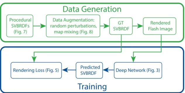
Figure 3.2: Overview of our method: we use procedural SVBRDFs to generate our ground truth (GT) training data, which we augment by random perturbations of the procedural parameters and mixing of the SVBRDF maps (Figures3.7and3.8, Section3.2). We then use physically-based rendering to synthesize the corresponding flash images. These are used to train our Deep Network (Figure3.3, Sections 3.1.1 and3.1.2) which compares predicted SVBRDFs and ground truth using a rendering loss (Figure3.5, Section3.1.3).
extraction and propagation.
Many important material effects are view-dependent, and as such ambiguous when ob-served in a single image. We tackle this challenge by defining the loss as a differentiable SVBRDF similarity metric that compares the renderings of the predicted maps against renderings of the ground truth from several lighting and viewing directions.
Combined together, these novel ingredients bring clear improvement over state of the art methods for single-shot capture of spatially varying BRDFs.
3.1
Network Architecture
Our problem boils down to translating a photograph of a material into a coinciding SVBRDF map representation, which is essentially a multi-channel image. The U-Net architecture [RPB15] has proven to be well suited for a wide range of similar image-to-image translation tasks [ZZI+17,IZZE17]. However, our early experiments revealed that
... ... Input 256 x 256 x 3 256 x 256 x 9 output Global features U-Net IN + lrelu conv FC concat FC selu IN conv selu Mean
Figure 3.3: Architecture of our deep convolutional network, which takes as input a single flash-lit image (left) and predicts four maps corresponding to per-pixel normal, diffuse albedo, specular albedo and specular roughness (right). Our network follows the popu-lar U-Net encoder-decoder architecture (black), which we complement with a new global features track (green) that processes vectors instead of feature maps. Taken together, the full network consists of repeating “modules”, which are detailed in the bottom part of the figure. At every stage of the network, the feature means subtracted by the instance normalization after the convolutional layer are concatenated with the global feature vec-tor, which is then processed by a fully connected layer and a non-linearity before being added to the feature maps of the next stage. IN and FC denote instance normalizations and fully connected layers respectively. We use SELU [KUMH17] and leaky ReLu acti-vation functions. In the decoder, the set of layers also includes a skip-connection con-catenation and a second convolution, which we omit for clarity. We provide the code of our network to allow reproduction.
despite its multi-scale design, this architecture remains challenged by tasks requiring the fusion of distant visual information. We address this limitation by complementing the U-Net with a parallel global features network tailored to capture and propagate global information.
3.1.1 U-Net Image-to-Image Network
We adopt the U-Net architecture as the basis of our network design, and follow Isola et al. [IZZE17] for most implementation details. Note however that we do not use their discriminator network, as we did not find it to yield a discernible benefit in our problem.
We now briefly describe the network design. We provide the code of our network and its learned weights to allow reproduction of our results2.
As illustrated in Figure 3.3, our base network takes a3-channel photograph as input and outputs a9-channel image of SVBRDF parameters – 3 channels for the RGB diffuse albedo,3 channels for the RGB specular albedo, 2 channels for the x and y components of the normal vector in tangent plane parameterization, and1 channel for the specular roughness. We use low dynamic range images as input photographs due to the ease of acquisition, and let the network learn how to interpret the saturated highlight regions. Regardless, the dynamic range of flash photographs can still be large. We flatten the dynamic range by transforming the input image into logarithmic space and compacting it to the range[0, 1] via the formula log(x+0.01)−log 0.01log(1.01)−log(0.01) .
The input image is processed through a sequence of8 convolutional layers that perform downsampling (the encoder), followed by a sequence of8 upsampling and convolutional layers (the decoder). Such a hourglass-shaped network gradually reduces the resolu-tion of the image while increasing the feature size, forcing the encoder to compress the relevant information into a concise, global feature vector. The task of the decoder is to expand these global features back into a full-sized image that matches the training target. However, while the bottleneck is critical to aggregate spatially-distant informa-tion, it hinders the reproduction of fine details in the output. Following Ronneberger et al. [RPB15], we mitigate this issue by introducing skip connections between same-sized layers of the encoder and decoder, helping the decoder to synthesize details aligned with the input at each spatial scale.
Prior to the decoder, we insert a single convolutional layer with 64 output feature chan-nels. The feature counts in the encoder downscaling layers are 128, 256, 512, 512, 512, 512, 512 and 512. The downsampling is implemented by using a stride of2 in the con-volutions. In the decoder, the same feature counts are used in reverse order. At each scale, a nearest-neighbor upsampling is followed by concatenation of encoder features, and two convolutions. We use the filter size[4, 4] across all layers. For nonlinearities we use the leaky ReLu activation function with a weight0.2 for the negative part. The final output is mapped through a sigmoid to enforce output values in the range[0, 1].
Following each convolution layer (or pair thereof), we apply instance normalization,
which stabilizes training on image generation tasks [UVL17,IZZE17]. Finally, we regu-larize by applying dropout at50% probability on the three coarsest layers of the decoder. 3.1.2 Global Features Network
Distant regions of a material sample often offer complementary information to each other for SVBRDF recovery. This observation is at the heart of many past methods for material capture, such as the work of Lensch et al. [LKG+03] where the SVBRDF is as-sumed to be spanned by a small set of basis BRDFs, or the more recent work of Aittala et al. [AWL15,AAL16] where spatial repetitions in the material sample are seen as mul-tiple observations of a similar SVBRDF patch. Taking inspiration from these successful heuristics, we aim for a network architecture capable of leveraging redundancies present in the data.
The hourglass shape of the U-Net results in large footprints of the convolution kernels at coarse spatial scales, which in theory provide long-distance dependencies between output pixels. Unfortunately, we found that this multi-scale design is not sufficient to properly fuse information for our problem. We first illustrate this issue on a toy example, where we trained a network to output an image of the average color of the input, as shown in Figure3.4(top row). Surprisingly, the vanilla U-Net performs poorly on this simple task, failing to output a constant-valued image. A similar behavior occurs on our more complex task, where visible residuals of the specular highlight and other fine details pollute the output maps where they should be uniform (Figure3.4, 2nd to 4th row).
In addition, we hypothesize that the ability of the network to compute global infor-mation is partly hindered by instance (or batch) normalization, which standardizes the learned features after every convolutional layer by enforcing a mean and standard devi-ation learned from training data. In other words, while the normalizdevi-ation is necessary to stabilize training, it actively counters the network’s efforts to maintain non-local in-formation about the input image. In fact, instance normalization has been reported to improve artistic style transfer because it eliminates the output’s dependence on the in-put image contrast [UVL17]. This is the opposite of what we want. Unfortunately, while we tried to train a U-Net without normalization, or with a variant of instance normal-ization without mean subtraction, these networks yielded significant residual shading in all maps.
(a) Input (b) GT Average (c) U-Net (d) Ours Normal Diffuse alb edo Roughness Sp ecular alb edo
(e) GT SVBRDF (f) U-Net (g) Ours
Figure 3.4: We trained a U-Net convolutional network to predict an image of the aver-age color of the input (top row). Surprisingly, the basic U-Net fails to produce a constant image (c). Similar artifacts appear when using the U-Net for SVBRDF prediction (f). We address this issue by complementing the U-Net with a parallel network that explic-itly computes and propagates global features. This approach succeeds in computing the average image (d) and reduces artifacts in SVBRDF maps (g).
We propose a network architecture that simultaneously addresses both of these short-comings. We add a parallel network track alongside the U-Net, which deals with global feature vectors instead of 2D feature maps. The structure of this global track mirrors that of the main convolutional track, with convolutions changed to fully connected lay-ers and skip connections dropped, and with identical numblay-ers of features. See Figure3.3
for an illustration and details of this architecture. The global and convolutional tracks exchange information after every layer as follows:
• Information from the convolutional track flows to the global track via the instance normalization layers. Whereas the standard procedure is to discard the means that are subtracted off the feature maps by instance normalization, we instead incorporate them into the global feature vector using concatenation followed by a fully connected layer and a nonlinearity. For the nonlinearity, we use the Scaled Exponential Linear Unit (SELU) activation function, which is designed to stabilize training for fully connected networks [KUMH17].
• Information from the global track is injected back into the local track after every convolution, but before the nonlinearity. To do so, we first transform the global features by a fully connected layer, and add them onto each feature map like biases. Our global feature network does not merely preserve the mean signal of a given fea-ture map – it concatenates the means to form a global feafea-ture vector that is processed by fully connected layers before being re-injected in the U-Net at multiple scales. Each pair of these information exchanges forms a nonlinear dependency between every pixel, providing the network with means to arrive at a consistent solution by repeatedly trans-mitting local findings between different regions. In particular, the common case of near-constant reflectance maps becomes easier for the network to express, as it can source the constant base level from the global features and the fine details from the convolutional maps (Figure3.4).
3.1.3 Rendering Loss
Our network outputs a set of maps that describe BRDF parameters, such as specular roughness and albedo, at every surface point. The choice of parameterization is arbitrary, as it merely acts as a convenient proxy for the actual object of interest: the spatio-angular
CNN
R
ender
er
Input
R
ender
er
Prediction
Ground truth
Figure 3.5: Our rendering loss compares the appearance of the predicted SVBRDF and ground truth by rendering both under the same random lighting and viewing configu-rations.
appearance of the SVBRDF. In fact, the parameterizations of popular BRDF models arise from a combination of mathematical convenience and relative intuitiveness for artists, and the numerical difference between the parameter values of two (SV)BRDFs is only weakly indicative of their visual similarity.
We propose a loss function that is independent of the parameterization of either the pre-dicted or the target SVBRDF, and instead compares their rendered appearance. Specifi-cally, any time the loss is evaluated, both the ground truth SVBRDF and the predicted SVBRDF are rendered under identical illumination and viewing conditions, and the re-sulting images are compared pixel-wise. We use the same Cook-Torrance BRDF model [CT82] for the ground truth and prediction, but our loss function could equally be used with representations that differ between these two quantities.
We implement the rendering loss using an in-network renderer, similarly to Aittala et al. [AAL16]. This strategy has the benefits of seamless integration with the neural network training, automatically-computed derivatives, and automatic GPU acceleration. Even complicated shading models are easily expressed in modern deep learning frameworks
Normal Diffuse alb edo Roughness Sp ecular alb edo Re-r endering
(a) GT SVBRDF (b) l1loss (c) Rendering loss
Figure 3.6: When trained with thel1 loss (b), the SVBRDF predicted by the network for
a test input image does not accurately reproduce the appearance of the target material when rendered. A network trained using the rendering loss (c) produces an SVBRDF that, while not necessarily identical in terms of the parameter values, reproduces the

![Figure 2.3: The Dome II, a BTF acquisition device developped by the University of Bonn [SSW + 14].](https://thumb-eu.123doks.com/thumbv2/123doknet/13091547.385405/24.892.130.766.160.602/figure-dome-btf-acquisition-device-developped-university-bonn.webp)
![Figure 2.4: Materials represented by their parametrization in the GGX [WMLT07] model and the associated renderings](https://thumb-eu.123doks.com/thumbv2/123doknet/13091547.385405/26.892.132.755.166.544/figure-materials-represented-parametrization-wmlt-model-associated-renderings.webp)
![Figure 2.5: Screenshot from the nodal interface of Substance Designer [All19a]. Design- Design-ing a material requires the creation of a complex graph of nodes.](https://thumb-eu.123doks.com/thumbv2/123doknet/13091547.385405/27.892.138.762.166.491/figure-screenshot-interface-substance-designer-material-requires-creation.webp)
![Figure 2.6: Capture setup of the method presented by Ren et al. [RWS + 11] using a linear source and a set of known BRDF.](https://thumb-eu.123doks.com/thumbv2/123doknet/13091547.385405/29.892.128.765.165.620/figure-capture-setup-method-presented-using-linear-source.webp)

![Figure 2.9: The U-Net architecture as described by Ronneberger et al. [RPB15]. We see the encoder decoder structure with skip-connections between them.](https://thumb-eu.123doks.com/thumbv2/123doknet/13091547.385405/33.892.132.762.163.589/figure-architecture-described-ronneberger-encoder-decoder-structure-connections.webp)