Design and Validation of a
Decentralized Biomass Torrefaction System
by
Kevin S. Kung
A.B., Physics, Princeton University (2008)
M.Phil., Physics, University of Cambridge (2009)
S.M., Biological Engineering, MIT (2013)
Submitted to the Department of Biological Engineering
in partial fulfillment of the requirements for the degree of
Doctor of Philosophy
at the
Massachusetts Institute of Technology
May 2017
Massachusetts Institute of Technology 2017. All rights reserved.
AuhrSignature
redacted
A u th o r ,. ... .. . .... .. . ... .. .. . ... .. .. .. .. . ..
Department of Biological Engineering
May 26, 2017
Certified by
...
Signature redacted
Adimed F. Ghonieni
Ronald C. Crane (1972) Professor
Thesis Supervisor
Accepted by...Signature
redacted
Mark Bathe
ARCHIVES
Chair, Graduate Program
M L i UTE
T N OGY
77 Massachusetts Avenue Cambridge, MA 02139
http://Iibraries.mit.edu/ask
MITLibraries
DISCLAIMER NOTICE
Due to the condition of the original material, there are unavoidable flaws in this reproduction. We have made every effort possible to provide you with the best copy available.
Thank you.
The images contained in this document are of the best quality available.
Design and Validation of a
Decentralized Biomass Torrefaction System
by
Kevin S. Kung
Submitted to the Department of Biological Engineering on May 26, 2017 in partial fulfillment of the
requirements for the degree of
Doctor of Philosophy in the Field of Biofuels and Renewable Energy
Abstract
To date, there has been limited usage of biomass and agricultural residues in rural areas as a form of renewable energv, mainly due to the expensive costs involved in collecting and transporting raw biomass. A decentralized biomass torrefaction system has the potential to upgrade the quality and transportability of distributed biomass residues in situ, thereby creating additional localized economic values and mitigating the environmental
consequences associated with open burning of the excess biomass residues. Nonetheless, most existing biomass torrefaction systems so far have been designed for large-scale, centralized deployment, and are unsuitable to be scaled down in decentralized applications due to their high level of sophistication and capital cost.
We propose a biomass torrefaction system based on the concept of torrefaction in a low-oxygen environment. By eliminating the stringent requirements of an inert torrefaction environment, we demonstrated that we can greatly simplify the reactor design and derive a laboratory-scale system that is also scalable. We proceeded to build and validate this
torrefaction system with respect to different operating conditions and types of biomass. Using a quantitative definition for torrefaction severity, we were also able to relate the various fuel user requirements in real life back to the fundamental reactor operations. By
quantifying in detail the overall energy performance, pressure requirements, and transient timescales, we also demonstrated how such a reactor system can be operated at scale, as well as the various design improvements that can further boost the performance of a scaled-up system. Therefore, this work builds the foundation towards the development of a low-cost, small-scale, and portable torrefaction system that can potentially be widely deployed in rural areas.
Thesis Committee:
Ahmed F. Ghoniem
Ronald C. Crane (1972) Professor of Mechanical Engineering, MIT
Alexander H. Slocum
Pappalardo Professor of Mechanical Engineering
Robert J. Stoner
Director, MIT Tata Center for Technology and Design
Scott R. Manalis
Acknowledgements
On many levels, this PhD thesis passes beyond just an intellectual journey into a spiritual one, and involves a host of people who have helped me and rooted for me during my time at MIT. The list below is my best attempt at digging through years of fading memories, and is, sadly, by no means comprehensive, but rather just a screenshot.
Coming from a physics background, many people had some difficulty relating why I wanted to move into engineering for graduate studies. I would like to thank the MIT Department of Biological Engineering for offering me a chance to study and make use of all the resources at this institute, and in particular, Professor Douglas Lauffenburger, for being flexible and letting me defer my graduate studies for one year while I study abroad. I would also like to acknowledge the members of BE Class of 2009-Rebecca Adams, John Casey Jr., Issac Chaim, Seymour De Picciotto, Jing Ge, Melissa Hanson, Kara Huang, Watthanachi
Jumpathong, Aaron Meyer, Deepak Mishra, Shengyong Ng, Nirmala Paudel, Miriam Sefta, Josephine Shaw, Adrian Slusarczyk, and Carrie Thompson-for supporting each other and studying together during the first year in the BE curriculum. Occasionally, especially during my latter years, often with a pang of panic, I am reminded that I am the last one in the Class of 2009 still remaining in the program, but I have no regrets whatsoever with the
somewhat extended detour that I took and all the rewards that I have reaped as a result.
At my time at MIT, I was first exposed to engineering and design in the context of resource-constrained considerations through my volunteer work with the MIT Engineers Without
Borders (EWB). I would like to acknowledge my MIT-EWB colleagues Helen D'Couto, Marisa Simmons, Rebecca Gianotti, Gajan Sivandran, Stephen Pennybaker, Rebecca
Heywood, Grace Teo, Chris Arsenault, Michael Zanchi, as well as the local Engeye team (John Kalule and Joseph). Dr. Alison Hynd was instrumental in supporting this project through a MIT Public Service Center fellowship and providing weekly feedback.
My exposure in engineering and design was further broadened through my engagement
with the D-Lab curriculum. I went to Ghana with Amy Smith, Kofi Taha, Mette Andersen, Raghu Mahajan, Mary Xu, Anita Lin, Elaina Present, Kellie Courtney, and Catherine Johnson. Also thanks to Pastor George Fuachie, Timothy Kyiu, Asante Johnson, Crossman Hormenoo, Master Stone and their communities in Kumasi, Swami Magazine, and New Longoro, for being such generous hosts and allowing me to learn. Following the D-Lab: Development class, I learned more about design with Nathan Cooke, Gwyn Jones, and Jack Whipple, and it was a pleasure to work with the Coriolis Centrifuge team, Daisy Chang, Kwami Williams, Melvin Salinas, and Roberto Melendez. Finally, I took the Development Ventures class with Joost Bonsen, and met wonderful colleagues who worked with me in developing the first development venture concept: Maria Davydenko, Ali Kamil, Mohit Kansal, David Lee, Rishi Trivedi, Coralie Vergez, and Nicole Yap.
It was in the Global Health Delivery Lab that I first encountered the seedling of the biomass torrefaction concept. This experience was made possible by Anjali Sastry, as well as my fellow student-consultants Alexandra Geertz, Sydney Atkins, and Nirav Patel. More
importantly, our local host in Carolina for Kibera opened the doors of their community to me, thanks to Hillary Omala, Ben Haggai, Jeffrey Okoro, Moses Ojwang, Erick Omondi, Erick Owour, Judy Mien, Norbert Aluku, Medina Abakar, Botul Sebit, the Jitunze Youth Group, as well as the Kibera Waste Recyclers.
As I developed the initial organic waste conversion concept further, it was Laura Sampath who was instrumental in helping me formulate this into a team and a project with a self-sustaining and self-growing prospect. It was during the Trash Talk at the IDEAS Global Challenge that Libby McDonald introduced me to Amy Banzaert and Kendra Leith, and gave me sharper project definition. Alison Hynd from the MIT Public Service Center, together with Laura Sampath from the former MIT International Development Initiative, Saida Benhayoune from the new D-Lab Scale-Ups program, and the Legatum Center provided the seed funding to help me explore this project more in depth. In addition to the formerly mentioned partners from Carolina for Kibera, I also had the pleasure of working with Will Ruddick, Jack Menya, Kenfield Griffith, Kenneth Owade, Dickson Kamau, Dr. Kamau Gachigi, and all the households and charcoal vendors we interviewed. This work forms the early section of the Takachar blog (takachar.blogspot.com). Thanks also to the following MIT students for being a part of this early journey: Jacob Young, Marie Burkland, Sophie Ni, Ala'a Siam, Yannan Zheng, Ya Lin, Vincent Liu, Yafei Han, Lyndsy Muri, Daisy Chang, and Viveka Mishra. Asanteni sana!
At this point, as I made a somewhat scary transition in my research focus from cancer research to renewable energy, several of my colleagues and mentors played a key role in supporting me and being flexible. This included Sandy Klemm, Ya Lin, Monica Wolf, Miaoqing Fang, Christoph Engert, Professors Terry Orlando, Douglas Lauffenburger, Scott Manalis, Forrest White, Alexander van Oudenaarden, and Carlo Ratti.
It was during a haphazardly arranged meeting with Prof. Alexander Slocum that the idea of doing a PhD thesis in biowaste conversion entered my mind. Dr. Robert Stoner and Prof. Sanjay Sarma instigated the possibility of carrying out such a project under the formative MIT-Tata Center, and introduced me to Prof. Ahmed Ghoniem, who, when I was about to give up on this pursuit, encouraged me to stay optimistic, and ultimately became my thesis advisor.
Having found support in the MIT-Tata Center, I traveled for the first time to India with Randy Kirchain, Rich Roth, Angi Acocella, Emmanuel Lim, Rachel Perlman, Caroline Howe, Devin Currie, and Jeremy Gregory. I am grateful to my local hosts in Hyderabad (Dr. Reddy and his colleagues at the WALAMTARI), Bangalore (Kamal Raj, Siddarth Kumar, Kuldeep Dantewadia, Almitra Patel, Mohini Acharya, Omer Kaiser), Pune (Dr. Anand Karve and Dr. Priyadarshini Karve), Chennai (Prof. Vinu and Deepak Ojha), Islampur (Shantilal Jakite, Mukund Deogaonkar, and Arkajit Mandal), Patna (Col. Baljit Singh and Manoj Sinha), Faisabad (Ambarish Singh), Delhi (Siddhartha Bountra), and Coimbatore/Ooty (Balram Warner, Mr. Aditya, and Mr. Annamalai). Thanks to the extremely competent staff at the MIT-Tata Center and the Tata Trusts-Wendy Duan, Jazy Ma, Darayes Shaw, Dickie
schedules. And thank you, of course, Sir Ratan Tata, for your personal support of this project and all Tata projects. ETIEIR!
I would like to thank all the students that have tolerated my mentoring over the past few
years and that have contributed in different ways to this project. This includes a master's student (Megan O'Brien), two S.B. thesis students (K.K. Wopat and Jonathan Rea), as well as a handful of UROPs (Meredith Barr, Ali Daher, Dheekshita Kumar, Tamanna Urmi, Abu Saleh, Jennifer Otiono, Gal Zeidman, Nikita Kodali, Marie Moudio, Neil Aggarwal, Aaron Gonzalez, and Tim Manganello).
I would like to thank my colleagues in the Reacting Gas Dynamics group (including Addison
Stark, Richard Bates, George Dimitrakopoulos, Akhilesh Bakshi, Xiaoyu Wu, Ashwin
Raghavan, Nadim Chakroun, Lorraine Rabb, Christos Altantzis, Gaurav Kewlani, Ray Speth, Cristina Botero, and Rajesh Sridhar), the Precision Engineering Research Group (including Dr. Nevan Hanumara, Sandy Campbell, and Kevin Simon), the MIT Energy Initiative
(including Randy Field and Navid Seifkar), Hobby Shop (Hayami Arakawa and Ken Stone), as well as my laboratory neighbors in NW14 as well as colleagues from the Environmental Health and Safety (EHS) for bearing with dusty and often foul-smelling experiments (Jim Doughty, Matt Orosz, Karen Cote, Dan Herrick, and Matt Fulton). Of course, thank you, Dean Maria Zuber, for letting us use the empty lab room in NW14, without which the
instrumentation would have been much more difficult to set up.
T wou~1ld] ll to rik thnk myr ,-i-lLab-rat-e-rcs t IIT-BPnmbay (Prnfesscnr Sanjay Mahajani, Dr. Son1 I VV LFUIL 0 111~A 1XL . .J 1ILLIIIIn toi 1AJiL&J3.i iJ rVX IE 11,1 _y %1AL%1 (AL IT_ n 1%u (P n ac n AL7 JILILJLL V Mn ni n Dr(L 1X%_L **qnnn]I A A - J-IT
Thengane, Ankita Gupta, and Ramesh Naidu) for assisting with the elemental analysis of the fuel samples, as well as at D-Lab (Dr. Dan Sweeney) for lending me the emission and
cookstove measurement equipment and set-up. Thank you, Jack Whipple, also for helping me weld the secondary oxidation device at moment's notice.
I would like to thank my family for their unconditional support, as well as Florina Feng,
with whom I have had the honor of being a life partner, both in the up times and the down
times. r- MG-f4 Tig
I would like to thank the funding sources that made this research possible. This included
the Dolores Zohrab Liebmann Fellowship for supporting my tuition and a large part of my stipend for three years, the Legatum Fellowship for supporting my stipend for the first two years, as well as the MIT-Tata Fellowship for supporting all the remaining expenses,
including my trips to India, the laboratory supplies, as well as all the capital equipment.
Last of all, thank you, Dr. Santosh Shanbhogue, for being a critical scientific mentor in my project. Thank you also once again, Dr. Robert Stoner, Professors Scott Manalis, Alex Slocum, and Ahmed Ghoniem for being on my thesis committee and being part of my journey for the past few years. You continuously challenged me to reach new heights, to
question my own assumptions as well as yours, and to achieve what had seemed to me four years ago only achievable by some form of miracle or magic. Thank you, in other words, for
Table of Contents
CHAPTER 1 CASE FOR DECENTRALIZED TORREFACTION ... 13
1.1 FATE OF UNUSED BIOMASS ENERGY AND ITS ENVIRONMENTAL IMPACTS...13
1.2 BIOMASS TORREFACTION AND ITS FUNCTIONAL EFFECTS... 19
1.3 OVERVIEW OF TORREFACTION REACTOR DESIGNS... 21
1.3.1 M O VIN G BED... 22
1.3.2 FLUID IZED BED ... 23
1.3.3 RO TA R Y DRUM ... 24
1.3.4 SCRE W CON VEYOR ... 25
1.3.5 M ICRO W A VE ... 26
1.4 NEED FOR A SMALL-SCALE, DECENTRALIZED TORREFACTION REACTOR DESIGN...27
CHAPTER 2 A LOW-OXYGEN TORREFACTION REACTOR DESIGN... 33
2.1 TORREFACTION IN A LOW-OXYGEN ENVIRONMENT... 33
2.2 PROPOSED REACTOR DESIGN CONCEPT ... 37
2.3 COARSE-GRAINED MODEL ... 38
2.3.1 MODELING DESCRIPTION ... 39
2.3.2 ANALYSIS OF HEAT TRANSFER PATHWAYS ... 43
2.3.3 IMPLICATIONS FOR REACTOR SIZING ... 44
2.4 FINE-GRAINED M ODEL ... 45
2.4.1 KINETICS AND THERMOCHEMISTRY SUBMODEL ... 46
2.4.2 GOVERNING EQUATIONS ... 47
2.4.3 PARTICLE SHRINKAGE ... 48
2.4.4 IMPLEMENTATION AND VALIDATION ... 49
2.4.5 RESULTS ... 49
2.5 DETAILED REACTOR DESIGN... 51
2.5.1 BIOMASS FEED COMPONENT ... 53
2.5.2 UPPER GAS SAMPLING PORT COMPONENT ... 53
2.5.3 MOVING BED COMPONENT ... 55
2.5.4 LOWER GAS SAMPLING PORT COMPONENT ... 55
2.5.5 OXIDATIVE ZONE COMPONENT ... 56
2.5.6 CHAR-COOLING SEGMENT ... 57
2.6 SUMMARY AND PERSPECTIVES ... 59
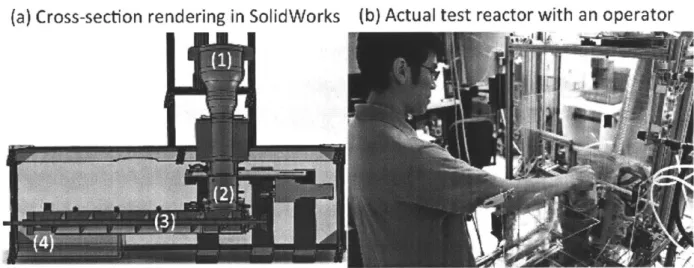
CHAPTER 3 VALIDATION OF A SCALABLE BIOMASS TORREFACTION REACTOR AND ITS PERFORMANCE METRICS ... 61
3.1 NEED FOR A SCALABLE TORREFACTION TEST REACTOR... 62
3.2 EXPERIMENTAL SET-UP AND DESIGN ... 63
3.2.1 CONTROL OF SOLID RESIDENCE TIME ... 63
3.2.2 CONTROL OF TORREFACTION SEVERITY ... 65
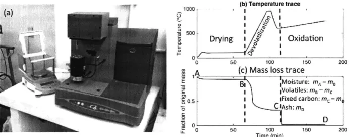
3.3 READOUT PROTOCOLS... 67
3.3.1 SOLID M A SS FLO W ... 68
3.3.2 PROXIMATE ANALYSIS ... 68
3.3.3 UL TIMA TE A NA L YSIS ... 69
3.3.4 HIGHER HEATING VALUE ... 69
3.4 VALIDATION OF STABLE OPERATING CONDITIONS... 70
3.5 REACTOR PERFORMANCE ANALYSIS... 76
3.5.1 ENERGY DENSIFICATION ... 76
3.5.2 SOLID M A SS YIELD ... 77
3.5.3 SOLID ENERGY YIELD ... 78
3.5.4 SOL ID PR OXIMA TE A NA L YSIS ... ... 79
3.5.5 SOLID ELEMENTAL ANALYSIS ... 80
3.5.6 VOLATILE ELEMENTAL ANALYSIS ... 81
3.5.7 NA TURE OF PRIMAR Y OXIDA TION ... 85
3.5.8 COMPOSITION OF REACTOR EXHAUST... 86
3.6 CHARACTERIZATION OF UNCERTAINTIES...89
3.6.1 INTRINSIC UNCERTAINTIES ... 90
3.6.2 EXTRINSIC UNCERTAINTIES ... 90
3.7 COMPARISON OF PERFORMANCE METRICS WITH EXISTING LAB-SCALE REACTORS...93
3.8 GENERAL APPROACH FOR RAPID REACTOR VALIDATION AND SCALING... 98
CHAPTER 4 A DESIGN-ORIENTED INDEX OF TORREFACTION...101
4.1 THE NEED FOR AN INDEX OF TORREFACTION ... 101
4.2 DEFINITION OF THE INDEX OF TORREFACTION...103
4.3 A MOTIVATING DESIGN CASE STUDY USING THE INDEX OF TORREFACTION ... 104
4.4.1 PROXIMATE ANALYSIS ... 107
4.4.2 ELEMENTAL (ULTIMATE) ANALYSIS...108
4.4.3 FUEL GRINDABILITY ... 109
4.4.4 SELECTED COOKING CHARACTERISTICS ... 118
4.5 GENERAL APPROACH FOR RAPID REACTOR VALIDATION AND SCALING...126
CHAPTER 5 ANALYSIS AND MITIGATION OF ENERGY LOSS MECHANISMS IN A TORREFACTION REACTOR ... 129
5.1 NEED FOR AN ENERGY-BASED METHOD FOR REACTOR IMPROVEMENT ... 130
5.2 TOTAL BIOMASS ENERGY FLUXES FROM THE REACTOR SYSTEM ... 131
5.3 CHARACTERIZING AND MITIGATION LOSSES FROM REACTOR SIDE WALLS...132
5.3.1 MEASUREMENT METHODOLOGY ... 133
53.2 RESUL TSAND DISCUSSION... ... 135
5.3.3 SCALING THE SIDE WALL THERMAL LOSS...136
5.3.4 OPTIMIZATION OF THERMAL INSULATION ... 137
5.4 CHARACTERIZING AND MITIGATING LOSSES FROM THE CHAR-COOLING SEGMENT ... 141
5.4.1 MEASUREMENT METHODOLOGY ... 141
E" A ) IV'CTTT 'PC' A A Tfl 1- VVy'rgIC n/f IT I A2 .J..p AF ) Li1 ) A D /UJL.~l 1 ...1... . .
5.4.3 PROPOSED AIR-PREHEA TING MECHANISM AND VALIDA TION STRA TEGY ... 144
5.4.4 AIR-PREHEA TING VALIDATION RESULTS ... 148
5.5 CHARACTERIZING AND MITIGATION LOSSES AND EMISSIONS FROM THE EXHAUST...153
5.5.1 MEASURING THE SENSIBLE ENTHALPY LOSS ... 154
5.5.2 MEASURING THE CHEMICAL ENTHALPYA VAILABILITY ... 154
5.5.3 EMISSION PROFILES AND COMPLETENESS OF SECONDARY COMBUSTION ... 160
5.5.4 CHARACTERIZATION OF UNCERTAINTY RANGES ... 165
5.5.5 DISCUSSION ON ENERGY LOSSES IN THE EXHA UST STREAM ... 167
5.6 SUMMARY AND PERSPECTIVES FOR IMPROVEMENT ... 169
CHAPTER 6 BULK HYDRODYNAMIC CHARACTERISTICS IN A BIOMASS MOVING BED AND THEIR EFFECTS ON SCALING ... 171
6.1 IMPORTANCE OF HYDRODYNAMIC DATA IN BIOMASS MOVING BED ... 171
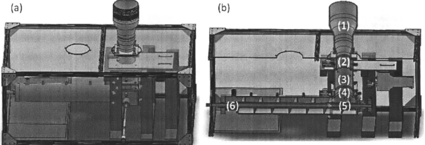
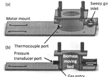
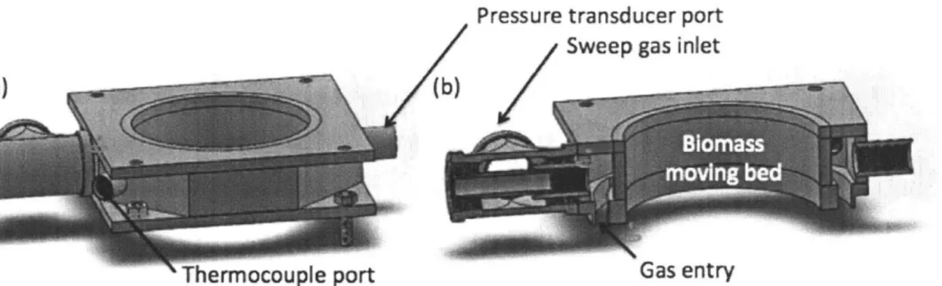
6.2 EXPERIMENTAL SET-UP ... 173
6.3 VALIDATION OF DARCY'S LAW IN BIOMASS MOVING BED...177
6.4 COMPARISON WITH EXISTING PERMEABILITY CORRELATIONS...179
6.6 DISCUSSION ... 189
CHAPTER 7 CHARACTERIZATION OF TRANSITION TIMESCALES IN SCALING BIOMASS REACTOR OPERATIONS...193
7.1 TRANSIENT RESPONSE OF THE REACTOR SYSTEM ... 193
7.2 ANALYSIS OF REACTOR THERMAL MASS ... 194
7.3 STARTING A REACTOR FROM COLD STATE ... 197
7.4 TW O METHODS FOR SHUTTING DOW N THE REACTOR ... 206
7.4.1 KEEPING THE REACTOR WARM ... 207
7.4.2 COOLING THE REACTOR QUICKLY ... 209
7.4.3 PERSPECTIVES IN COOLING THE REACTOR ... 214
7.5 TRANSITIONING BETW EEN TW O REACTION CONDITIONS...215
7.6 DISCUSSION ... 217
CHAPTER 8 PERSPECTIVES AND FUTURE W ORK ... 219
Chapter 1
Case for Decentralized Torrefaction
Biomass-such as post-harvest agricultural residues-represents a vast untapped value for energy and other applications. However, most of the world's biomass resources are located in remote distributed locations, which make the logistics of conversion and
utilization expensive. In this Chapter, the goal is to present a case for decentralized biomass torrefaction as a strategy to locally densify and process the excess biomass resources, so that they can be stored longer in solid form and more easily consumed locally and/or transported and processed. A review of the existing biomass torrefaction technologies
reveals that they tend to be too large-scale and complex to be compatible with
decentralized biomass torrefaction. We therefore define the functional requirements for enabling the design of such a system, and propose a simplified but scalable low-oxygen moving bed reactor design concept that we will study and quantify further for the rest of this thesis.
1.1 Fate of Unused Biomass Energy and Its Environmental Impacts
Biomass, as loosely defined, consists of organic materials produced by the photosynthetic activities of plants. These can include trees, grass, agricultural products, and their residues. The term lignocellulosic biomass gives the term more specificity, by referring to the three
main constituent components of biomass: cellulose, hemicellulose, and lignin. Indeed, many studies in the literature have assumed that the diverse types of biomass can all be broken down into different combinations of cellulose, hemicellulose, and lignin (Perez et al., 2002; Yang et aL., 2006). Because biomass is very diverse, as summarized in Table 1, in the
remainder of this Chapter, in order to motivate the discussion and design goals, we will be focusing only on a specific sub-type of biomass: agricultural residues, especially those agricultural residues in India. However, the work done in this thesis is applicable to all types of biomass throughout the world, including those that are non-agricultural in origin.
Table 1 - Classification of different types of biomass, and examples of each (adopted from
Nhuchhen et aL., 2014). Our discussion will be primarily on agricultural residues.
Class Type Examples
Forestry Dedicated forestry Short rotation plantations (willow, eucalyptus, etc.)
Forestry products Wood blocks and chips
Agriculture Crops and residues Oil seeds, sugar crops, starch crops, straws, pruning
Livestock Wet and dry manure
Industry Sawdust, paper industry waste
Others Garden waste Pruning and grasses
Contaminated Municipal solid waste, sewage sludge, demolition wood
Many people are interested in biomass because of its potential as a mostly renewable energy resource: the plant matter can be converted into carbon dioxide and water, releasing energy in the process, whether through rapid oxidation such as combustion or gasification, or through slower biological conversion such as anaerobic digestion or aerobic composting. While biomass can be converted into other valuable uses, such as fertilizer, animal mulch, and even structural materials, in this thesis, we focus specifically on the energy potential of biomass.
What are some examples of common agricultural residues, and what are their respective energy potentials? This figure is notoriously difficult to obtain on a macroscopic level, but studies such as Lal (2005) have begun to help shed light into this worldwide potential. As summarized in Table 2, most of the world's agricultural residues can be broken down into four families: cereals (e.g. barley, corn, millet), legumes (e.g. beans, chickpeas, groundnut), oil crops (e.g. linseed, sesame, sunflower), and sugar crop (e.g. sugar beet, sugarcane, potatoes). Altogether, Lal (2005) estimates that the total crop residue is about 3.8 billion tons/year. In terms of energy equivalent, this is about 69.9 exajoules (1018
J),
or about 60 quads-which is sufficient to satisfy the primary energy demand of 13.5% of the world.Table 2 - Worldwide biornass potential as an energy resource in 2001 (Lal, 2005).
Crop family Worldwide crop production Worldwide crop residue
Cereals 2.1 billion tons/year 2.8 billion tons/year
Legumes 305 million tons/year 305 million tons/year
Oil crops 79 million tons/year 108 million tons/year
Sugar crop 677 million tons/year 170 million tons/year
While the worldwide biomass potential is enormous, different geographical regions have different types of biomass and different energy needs. Thus, a broad discussion without geographical specificity is likely going to bewilder rather than to aid the development of the main goals of this thesis. To be more specific, we start by examining the case of biomass utilization in India, while keeping in mind that this specific case is also generalizable to many other regions and contexts in the world.
Done in a similar spirit as Lal (2005), a more recent study by Hiloidhari et aL. (2014)
examines the bioenergy potential from biomass in India. Figure 1(a) illustrates the residues from the different crop types found in different Indian states, as well as their contribution to the overall energy potential. Figure 1(b) represents this information on a map,
normalized by the population. We observe that there is a significant geographical disparity: this surplus biomass energy potential is greatest in the western states such as Gujarat and Maharashtra (> 10,000 MJ/year per capita) while it is the least in the eastern and northern states such as Mizoram, Bihar, and Jharkhand (< 1,000 MJ/year per capita). Altogether, Hiloidhari et aL. estimated that the total surplus biomass provides an equivalent of 4.15 exajoules of energy per year, or 132 GW of energy availability in the country.
(a) . 750 700 S650 4600 550 50 50
4
00 250 200 10 000Oth" 01- Hictauural wSugar OPuksm 00Oi Ui
Figure 1 -Energy potential of surplus biomass in India, from Hiloidhari et al. (2014). (a) Breakdown of the energy potential from different crop types by different states in India. (b) Map of the surplus biomass energy per capita in different states.
Table 3 - Breakdown of the capacities of biomass-related energy generation in India (MNRE, 2016) as of March 31, 2016.
Sector Capacity
On-grid power (combustion, gasification, bagasse cogeneration) 4,831.11 MW
On-grid waste to power 115.08 MW
Off-grid biomass (non-bagasse) cogeneration 651.91 MW
Off-grid biomass gasifiers (rural) 18.15 MW
Off-grid biomass gasifiers (industrial) 164.24 MW
Off-grid waste to energy (power, heat) 160.16 MW
Total installed capacity 5,941 MW
Total surplus biomass energy potential (Hiloidhari et al., 2014) 132,000 MW
Yet when we see a breakdown of the biomass energy utilization in India, we note a stark discrepancy: currently, only 5.94 GW, or 4.5% of the total surplus biomass energy potential, is being utilized as energy, as listed in Table 3. This then begs the question: What happened to the remaining 95% of the surplus biomass energy potential? To say that most of the remaining biomass is being used for other non-energy purposes such as fertilizer
(compost) or animal mulch is hardly accurate, as Hiloidhari et aL. in their biomass energy estimation already considered and subtracted these other competing uses from the overall biomass energy availability. While the current literature is lacking on a detailed accounting for the fate of the remaining 95% of the energy potential, we can make some educated guesses based on what is often observed in the field, often based on specific types of biomass and its fate.
One of the most well studied cases of the fate of agricultural residues is that of post-harvest rice stubbles in the Punjab State in India. Anyone who has traveled to rural parts of India during October and November may be familiar with sights of open biomass burning in the field (Figure 2a). It is estimated that the Punjab State produces about 17 million tons of rice stubble every year, and of that, more than 90% is being burned in the open (Milham et aL, 2014). As seen in a satellite image (Figure 2b) taken by NASA, this burning releases tremendous amounts of atmospheric aerosols. These aerosols can travel thousands of kilometers, and is considered a major contributor to urban smog in places like Delhi
(Subramanian, 2016). Therefore, the negative public health effects of aerosol inhalation (van der Werf et aL, 2006; Pandey et aL, 2005) extend beyond just the local regions where the open burning occurs, to large metropolitan areas with millions of people. Furthermore, these atmospheric aerosols have historically contributed to a significant uncertainty in modeling climate change (Andreae et al., 2005; Ramanathan et aL, 2007; and Sharma et aL, 2010). A more recent modeling study (Jacobson, 2014) suggests that open biomass burning can contribute up to 18% of global anthropogenic C02 emissions.
While it is not within the scope of this work to try to track down the fate of the different types of surplus biomass in India or in the world, it suffices to say that (a) a significant portion of the energy potential from the surplus biomass is not currently being utilized, and
(b) some of the surplus biomass is being burned in the open, which is not only a waste of
resources and energy, but also contributes to air pollution, negative public health
outcomes, and global climate change. The next question is: What are some common factors that prevent this surplus biomass energy from being harnessed?
Figure 2 -Evidence of biomass burning. (a) Burning of stubbles in a rice field in the Punjab State of India (Martin, 2014). (b) A NASA satellite image showing the macro-scale
particulate plumes associated with biomass burning in Punjab, India (NASA, 2015).
While the use of biomass energy is highly context-dependent, a survey of the existing literature reveals some outstanding difficulties in harnessing this biomass energy in rural areas. Most types of agricultural biomass residues do not present themselves in a form that cannot be easily manipulated. For example, due to the high moisture content, and low mass and energy density in its native state, biomass is often very costly to transport and process without some preprocessing step, such as baling or pelleting, that improves the density and other transportation-related characteristics (Hess et al., 2007; and Eranki et aL, 2011). In some cases, it may make sense to set up a biomass energy supply chain in the vicinity of an industrial cluster with an intensive energy demand (for example, Chattopadhyay et aL,
2016). On the other hand, in many cases, the location of energy availability and the location
of energy demand are frequently not contiguous (Lin et al., 2016). In such cases, significant amount of energy and cost can be expensed in bringing the agricultural residue from one location to another, and this therefore limits the territory around a biomass energy plant where biomass collection and transportation are feasible (Survilo and Beryozkina, 2016). As an example, an interview that the author carried out with the Biomass Power
Association revealed that for many biomass power plants, the cost of collecting and transporting the biomass feedstock can comprise 90% of the operating costs. This often limits the feasible transportation to a radius of less than 30 kilometers from the plant
(Cleaves et aL, 2015).
Due to these logistical challenges in a centralized biomass processing facility, recent studies have shown increasing interest in a decentralized mode of biomass utilization. Lamers et al. (2015), for example, propose a network of decentralized biomass depots to make biofuel production and utilization more economical. While such concepts are commendable, their actual implementation is still questionable. One reason is that the majority of biomass processing and utilization technologies are, by and large, designed to be large-scale and centralized. While decentralized and off-grid biomass technologies, such as some small-scale gasifier or combustor designs (< 100 kW), have existed for many years (Dong et al,
2009; and Arena et aL, 2010), they mainly produce combustible gases, heat or power, and
herein lies a central problem: these forms of energy are either not readily storable, or have a high cost of energy storage. Consider the fact that in rural, decentralized areas, surplus biomass is not available constantly, but often is only available during one or at most two peak seasons immediately after harvest, and the fact that this biomass has a limited lifetime (before the land needs to be cleared, or before the biomass starts to decompose, for
example), then we can see that it becomes a significant challenge to not just to harness this seasonal energy supply, but also to store it in a decentralized and cost-effective manner so that it can be used in off-seasons where surplus biomass residues are not readily available. The question then becomes as follows: In decentralized biomass processing, if gases, heat, or power do not provide an easily storable form of energy, can we identify technologies or processes to store this energy instead in a non-reactive solid form without requiring specialized storage containers?
1.2 Biomass Torrefaction and Its Functional Effects
Our interest in biomass torrefaction arises as a potential answer to the question posed at the end of the previous section. Biomass torrefaction is a pretreatment process whereby lignocellulosic biomass such as agricultural residue is subject to an elevated temperature of typically between 200-320'C for a timescale of minutes to hours. Under such conditions, the biomass undergoes chemical changes in the form of devolatilization, whereby the low-energy molecules such as water, carbon dioxide, carbon monoxide, and organic acids leave
the biomass in the form of volatile gases rich in hydrogen and oxygen. Because these low-energy molecules carry mass away to a greater extent than they carry away low-energy, what remains in the torrefied solid becomes more energy dense (both on mass basis and on volumetric basis) and more carbon-rich. This results in a visual change of color in the appearance of the biomass (Figure 3).
Figure 3 -Visual appearance of pine shavings as they are increasingly torrefied from (a) to (e) (O'Brien, 2016).
As a result of this energy densification, the cost of transporting torrefied biomass is reduced on an energy basis, as the same truckload of torrefied fuel now contains more energy compared to the original case of raw biomass fuel. Furthermore, torrefied biomass has been shown to be more hydrophobic, which means that it is resistant to moisture attack and does not tend to degrade over time (Acharya and Dutta, 2015). Therefore, torrefied biomass can be stored as a stable fuel for a much longer period of time compared to its raw biomass counterpart. Table 4 lists some of the functional changes to the biomass fuel as it becomes torrefied.
Table 4 - Changes in the functional characteristics of biomass fuel upon torrefaction.
Criterion Raw biomass Torrefied biomass
Bulk density 200-250 kg m 3 550-850 kg m-3
Mass energy density 9-15 MJ kg-' 19-25 kg-1
Volumetric energy density 2-3 GJ m-3 15-19 GJ m-3
Energy transportation cost -$0.020 GJ km-1 -$0.016 GJ-1 km-1
Native moisture content 10-50% (hydrophilic) 1-5% (hydrophobic)
Storage shelf-life Weeks (biodegradation) Months
As can be seen in Table 4, the various challenges in decentralized biomass processing can be directly addressed by torrefaction. In addition, there are other features of biomass torrefaction such as decreased energy requirement for grinding the torrefied biomass into smaller pieces (Li, 2015); while they do not directly improve transportability and storage, they do confer advantage to the subsequent solid fuel processing, because many solid fuel boilers-especially of fluidized bed design-require that the incoming fuel feedstock by pulverized.
Finally, the volatile gases released by the biomass feedstock during the torrefaction process contain energy and can be combusted. Therefore, this heat can, in theory, be harnessed to supply the heat source to the torrefaction reactor itself, without requiring external energy. This autothermal nature of biomass torrefaction under certain conditions is a key to a scalable biomass torrefaction process.
1.3 Overview of Torrefaction Reactor Designs
Given these functional changes that can be effected on the biomass upon torrefaction, we come to the conclusion that torrefaction is a promising preprocessing step in order to overcome the aforementioned challenges with using surplus biomass in rural areas. In this section, we explore some of the existing torrefaction technologies. In the following section, we explain why they have been ineffective so far in addressing the utilization of
agricultural residues.
The basic functional requirement of a torrefaction reactor is that (a) it needs to heat the biomass up to a certain target temperature range, and (b) it needs to convey biomass continuously. In this section, we discuss several common types of reactor design that can satisfy the criteria above. While our list below is not exhaustive, it represents the most common varieties in existence.
1.3.1 Moving Bed
A vertically oriented reactor where a packed bed of biomass migrates downwards, driven by gravity. Towards the bottom of the reactor, the temperature steadily increases as the
biomass travels downwards. At the base of the reactor, a mechanism (e.g. screw auger) continuously removes torrefied biomass from the reactor. The temperature gradient can be set up by the injection of hot gases directly into the bottom of the moving bed, and the hot gases then flow upwards (counter-flow) through the moving bed. The temperature
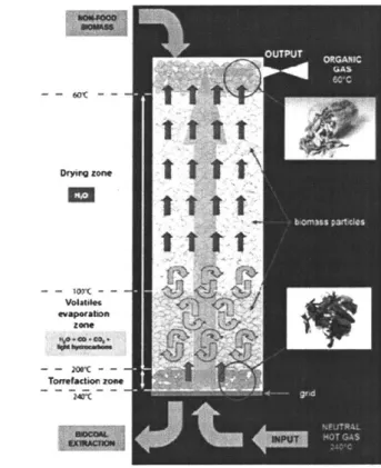
gradient can also be set up by the conduction of heat into the moving bed from the exterior in an indirect fashion. One example of a moving bed reactor (Figure 4) is the TorspydTM design by Thermya (France), and then validated in modeling by Ratte et al. (2011).
Dr,~zone
-o~ci
tilt
FigUre 4 - Thie Tor-spydT'm column, an example of a moving bed torrefaction r-eactor design
(Ra tte et aL, 2011)
The advantage of a moving bed reactor is that it is possible to completely fill the reactor volume with biomass (unlike some other designs to be discussed below). Therefore, for a
which translates to a smaller capital cost. The main disadvantage is that the moving bed reactor is often prone to inhomogeneity in the heat transfer process, as the biomass is typically not stirred. This inhomogeneity is especially pronounced when an indirect heating method (e.g. heat conduction from the side or bottom walls) is involved.
1.3.2 Fluidized Bed fluid flow
it
I~
prkii W~ verumf Aseparstion of particles inl 0.11CrFigure 5 - Different view of Torbed, a modified fluidized bed torrefaction (Eseyin et al., 2015; TorffTech, 2017).
I
r eactor design
Like the moving bed reactor design, there is also a packed bed of solid biomass of very small particle sizes, but the difference is that the packed bed is also filled with a heat carrier solid (e.g. sand) with a high specific heat capacity. However, in this case, hot gases are injected directly into the packed bed at a much higher velocity-often around 50-80 m s-(Koppejan et al., 2012)-than in the moving bed design, such that the solid particles (both biomass and the carrier solid) will be carried by the gases and move about vigorously, almost like a fluid-hence the name fluidized bed (9). Because of the extensive gas-solid mixing, heat conduction from the hot gases to the solid particles is rapid and homogeneous. However, it becomes difficult to separate the biomass particles from the heat carrier solid particles. Laboratory-scale experiments have also reported a significant amount of losses in the torrefied fines (10). One example of a fluidized bed reactor is the Torbed design (by
sg.*"
W'"~
so I
ew~ fruim - ~
Topell in the Netherlands) (Figure 5), in which due to the high rate of heat transfer, the average residence time of biomass inside the reactor is only about 80 seconds, therefore resulting in a small reactor size for a given production capacity (Koppejan et aL., 2012).
1.3.3 Rotary Drum
The reactor consists of a slightly downward inclining cylinder that rotates. Biomass enters into the higher end of the cylinder, and as the cylinder rotates, the biomass also tumbles (Figure 6). Due to this tumbling motion, the typical biomass particle alternates in its contact with the hotter reactor wall and the gas inside the reactor, resulting in a relatively good mixing and homogeneous heating. However, the volatiles released inside the rotary drum typically needs to be combusted elsewhere and then redirected back to the outside of the reactor, necessitating an indirect mode of heating through the wall of the rotary drum, and this therefore imposes some heat transfer limitations. Another major limitation is that, in order to support the solid tumbling motion, the maximum fill volume of the reactor is limited to about 30% (Barr et aL 1989; and Boateng and Barr, 1996). This means that for a given rated production capacity, the volume of the reactor will be at least 3 times bigger than, for example, a completely filled moving bed reactor, thereby resulting in a higher capital cost. On the other hand, one benefit of a rotary drum design is that it is a relatively proven technology with other applications such as biomass drying and pyrolysis (for example, Benanti et al., 2011), as well as chemical looping (Zhao et al., 2012; and Zhao et al., 2014). Therefore, quite a few companies have developed torrefaction technologies based on the rotary drum design-using either existing rotary drum suppliers or developing custom-designed parts-including Atmosclear (Switzerland), Bio Energy Development North (Sweden), Earth Care Products (USA), Renergy (the Netherlands), and Torr-Coal (the Netherlands). Recent studies, such as one by Bates and Ghoniem (2014), have also considered the coupled phenomenon of torrefaction thermochemistry and heat transfer within thermally thick biomass particles, especially in the fluidized bed setting, as
Figure 6 - Photograph (Thamer, 2013) and cross-sectional schematic visualization (Li et aL, 2002) of a rotary drum reactor.
1.3.4 Screw Conveyor
This is typically a horizontally or vertically oriented reactor, with one or more screw augers that rotate in order to continuously convey biomass through the system. The hot gases are often provided to the outside of the reactor or within the hollow shaft of a screw, and the heat is indirectly transferred to the biomass. The heat transfer, however, is
somewhat better than the rotary drum, as in addition to the heated outer wall, the screw itself can also be heated, thereby providing a larger surface area for more effective heat exchange. Like the rotary drum, in order to work properly, the screw conveyor cannot be completely filled. Therefore, for a given biomass processing capacity, the reactor volume must be significantly larger. Like the rotary kiln, the screw conveyor is also a relatively proven technology, with various existing torrefaction designs such as BTG (the
Netherlands) (Figure 7a), Foxcoal (the Netherlands), and Biolake (the Netherlands). Furthermore, the author and his colleagues, in an earlier iteration of the torrefaction reactor design, also built and experimented with a small-scale vertically oriented screw conveyor. The learning from this operation, as well as a subsequent proposed improved design involving a horizontal screw conveyor design, are documented in O'Brien (2016) (Figure 7b).
I. Storage and Feed
2. Reactor andi Heat Exchanger
Figure 7 - Two examples of screw conveyor torrefaction reactor designs. (a) The BTG system (BTG, 2017), and (b) a system proposed by O'Brien (2016).
1.3.5 Microwave
The microwave reactor uses radiation energy to heat up the biomass, allowing it to reach torrefaction conditions. Several laboratory-scale experiments have been carried out (Wang et aL, 2012; and Satpathy et aL, 2014) (Figure 8a); however, limited work so far has been done to scale the design up (Shang, 2012). A few examples of commercial pilots include Rotawave (UK), CanBiocoal (UK), Airex (Canada), and Torrefaction Systems (USA). While heating from microwave can be rapid and uniform (Ren et aL, 2012), which can reduce the solid residence time and reduce the reactor size for a given solid throughput (Huang et aL, 2012), this is shown to cause drastic intra-particle temperature and torrefaction
inhomogeneity in thermally thick biomass particles (Dhungana et al, 2012) (Figure 8b). Another major disadvantage of using a microwave reactor is that the radiation energy required is most easily generated by electricity, and is otherwise very difficult to convert from either heat or the chemical energy contained in the volatile gases released from the torrefaction process. The complexity associated with generating microwave radiation also means that there is often a high capital cost and operational expenses associated with an at-scale design.
Figure 8 - Microwave torrefaction. (a) An example of a microwave torrefaction reactor set-up (Satpathy et al., 2014). (b) Microwave torrefaction can result in severe intra-particle inhomogeneity for thermally thick particles (Dhungana et al., 2012).
1.4 Need for a Small-Scale, Decentralized Torrefaction Reactor Design
As summarized in Section 1.3, there exists various torrefaction reactor designs, in different stages of commercialization. While the list is not exhaustive, it does encompass the most common types of biomass reactors. The advantages and disadvantages of the different designs are summarized in Table 5.
Table 5 - A summary of the advantages and
reactor designs.
disadvantages of the different torrefaction
Reactor type Advantages Disadvantages
Moving bed High degree of filling Heat transfer inhomogeneity
Fluidized bed High heat transfer, Separation of biomass from solid heat carrier
uniform particles; fines losses
Rotary drum Proven Low degree of filling, heat transfer limitation
Screw conveyor Low cost, proven Low degree of filling, heat transfer limitation
Microwave Homogeneous and High capital cost and sophistication;
intra-rapid heating rate particle inhomogeneity
4M
Table 5 summarizes the representative commercial designs of the torrefaction reactor as well as their designed full-scale capacity, and we begin to see a potential problem. That is, most of these existing torrefaction reactors have been designed with a large-scale
operation in mind (between 1-33 tons/hour) for the operating context of primarily Europe and North America, often in the vicinity of a large biomass producer such as a lumber mill or an agricultural processing mill. Can any of these existing technologies be feasibly scaled down and applied to the rural, decentralized context, in order to overcome the issues of biomass transportability and storability discussed earlier in Section 1.2?
In order to understand the scale requirements of decentralized biomass torrefaction, let us consider a potential use case in rural India. While there is a wide distribution in the sizes, the typical farm size in South Asia is around 1.3 hectares and decreasing (Lowder et al.,
2016). While the yield of agricultural residues per hectare is also highly dependent upon
the soil conditions, rainfall, fertilizer applied, and so forth, we have assumed that a
representative value is 2.25 tons/hectare (Laurin and Chamberland, 1981) upon harvest. This means that a representative farm in rural India may have about 3 tons of
post-agricultural residues to be processed, and these farms are spread geographically amongst a large rural region. If, as discussed in Section 1.2, transporting the raw, unprocessed
agricultural residues to a centralized processing facility is to be avoided due to the high logistical costs, then the only option for a decentralized biomass processing system is to be portable, moving from farm to farm and conducting the biomass upgrading on-site.
Assuming that a rural community operates one or a few of these biomass torrefaction reactors, and that the different farms/regions-which harvest on slightly different dates-are also visited by the reactor on different days, then we conclude that a decentralized torrefaction reactor not only has to be small-scale, portable, low-cost, and low-maintenance in a resource-constrained setting, but it also must have a biomass processing capacity of around a few tons per day.
Table 6 - Design production capacities of different torrefaction technologies (Thran et aL,
2016)
Torrefaction Technology Design Production Capacity
Torr-Coal (the Netherlands) Rotary drum 4,500 kg h-1
BioEndev (Sweden) Screw conveyor 2,100 kg h-1
Solvay (USA) Screw conveyor 33,300 kg h-1
Topell (the Netherlands) Fluidized bed 8,000 kg h-1
River Basin Energy (USA) Fluidized bed 6,000 kg h-1
ECN (NL) / Andritz (Denmark) Moving bed 1,000 kg h-1
Thermya/Areva (France) Moving bed 2,500 kg h-1
As we examine Table 6, we see that most the current commercial torrefaction reactor designs have a scale mismatch by at least a factor of 10. However, can any of these existing reactor designs be scaled down and be applied in a decentralized manner? If so, what would be the resultant capital installation cost? Data for the capital installation costs of the
existing commercial technologies, especially for a hypothetical scaled-down reactor design, are notoriously difficult to obtain. Instead, we sought the reactor techno-economic analysis literature for the approximate scaling law for capital expenditure associated with biomass reactors:
(Size_
2\scale factorCostsize 2 = Costsize 1X Size 1)
where the scale factor has been empirically determined to be around 0.6-0.8 (Jenkins,
1997; Flynn and Searcy, 2009; Bain and Overend, 2002; and Flynn et aL, 2003) in biomass
reactor applications, including torrefaction (Svanberg et aL, 2013). We therefore adopted a scale factor of 0.7 for our approximation. We further assume that the size of the reactor is directly proportional to the biomass processing capacity of the reactor. Based on the capital cost estimates for torrefaction reactor systems given by Pirraglia et aL (2013) and existing commercial data, we concluded that a hypothetical scaled-down torrefaction reactor at 5 tons/day would cost between $96,000 and $320,000. How does this cost compare with the affordability in rural areas? To obtain an order-of-magnitude estimate of the latter, we first
assume that a rural village in India contains a population on the order of 1000 people (Singh et aL, 2006), with a median income of about US$630/year (Times of India, 2016). This yields an approximated total GDP of about $1 million/year in a typical Indian rural village. A reactor unit with a capital cost of around 15-50% of the entire village's annual
GDP is clearly out of the price range. Why do the existing biomass torrefaction reactor
designs cost so much?
Upon analyzing the common designs for existing torrefaction reactors (for example, Figure 4 through Figure 7), our hypothesis as follows: the current torrefaction reactors are
capital-intensive because they incorporate many sophisticated features to boost their performance. Consider the case of harnessing energy from the volatile gases. Most of the existing technologies collect the volatile gases, cool them, scrub moisture from the mixture, inject with air in an external burner, and then recycle the hot post-combustion gas back to heat the torrefaction reaction at a specified temperature. As the volatile gases tend to be low in energy density and difficult to burn completely, this multi-step process upgrades the quality of the volatile gases and better controls the overall energy efficiency. While these cleaning/upgrading components do not add significantly to the cost of a large-scale
torrefaction reactor while conferring energy benefits as described above, they can pose as a major barrier for scaling down existing torrefaction reactor designs. In a scaled-down torrefaction reactor design for decentralized deployment, is it possible to sacrifice some of the performance characteristics of a large-scale torrefaction process in order to exchange for a more simplified design with a more affordable capital installation cost?
The natural follow-up question becomes as follows: What is an affordable capital
installation cost? To get an order-of-magnitude estimate of this figure, we use two distinct approaches. First, we note that typically, a village-based production utilizing biomass torrefaction may also require other peripheral hardware equipment for the
post-processing of this fuel locally-such as grinding and pelleting-into suitable fuel. Based on the author's personal experience managing a solid fuel company in Kenya, such peripheral hardware typically costs several thousand U.S. dollars, such that the village-based
affordable torrefaction unit should also fit comfortably within this budget range. Second, we note that a 5 tons/day processing of biomass would yield between 1-3 tons/day of torrefied fuel, depending on the moisture content as well as the torrefaction severity. Based on the author's experience in Kenya and India, comparable solid fuels in the market
typically fetch $200-600/ton in price. Assuming a medium production of 2 tons/day of torrefied fuel, and assuming a medium price of $400/ton, this implies that a torrefaction reactor can generate about $800/day of revenue for the operator. Assuming that the local village has two harvest seasons, each lasting about 60 days, and that the torrefaction reactor is fully operational during these seasons. This implies that in one year of reactor operation, the revenue is about $100,000. Crudely assuming a 20% gross margin, we see that the gross profit is around $20,000/year. In order for the torrefaction conversion to be an interesting business proposition to a local entrepreneur or investor, the return on investment of 1-2 years is reasonable. This implies that the capital expenditure of the entire torrefaction system cannot be more than about $10,000-30,000. Therefore, we see that the two distinct methods of capital expenditure estimation yields a similar upper limit on the capital cost of a decentralized torrefaction reactor system to be on the order of
$10,000. This represents roughly a one-tenth reduction in the capital expenditure of the
sized-down versions of the current commercial torrefaction reactors.
While in this thesis, it is premature to put an exact final system cost just based on the work of a laboratory-scale prototype, the number above does give us a motivating design
constraint. Therefore, in this thesis, can we come up with a significant design simplification and demonstrate its performance functionality-and therefore potential subsequent
capital expenditure saving-in scaling such a torrefaction reactor designed for decentralized deployment?
This question becomes the central theme for the remainder of this thesis, and as we will demonstrate, an affirmative answer will be the major contribution of this thesis to the current state of the art. In Chapter 2, we consider torrefaction in a low-oxygen
environment, and describe a scalable laboratory-scale moving bed reactor design that is more simplified in comparison with the reactor designs we have seen above. In 0, we
validate the operation and key performance metrics of this reactor under various
torrefaction reaction conditions and types of input biomass feedstock. In 0, we utilize the performance maps obtained in 0 to devise a simplified and design-oriented approach to select the torrefaction reactor condition based on the index of torrefaction, and show how to operate the reactor in order to satisfy different end user requirements on energy
density, fixed carbon content, stove temperature, grindability, and even combustion emissions profile. This also serves to verify that the various biomass improvements associated with the classical inert torrefaction still exists in our low-oxygen torrefaction reactor. In 0, we consider various energy loss mechanisms in the current laboratory-scale reactor, and arrive at a science-based approach to improve the design of a scaled-up version through optimal insulation, air pre-heating, and secondary oxidation of
uncombusted volatiles in the reactor exhaust stream. In Chapter 6, we consider what it takes to inject a specified flow rate of air into the reactor in order maintain a low-oxygen environment by characterizing the hydrodynamic characteristics of the biomass moving bed, and using a combination of the natural stack effect and, in some cases, forced air. Finally, in 6.1, we consider what it takes to start the reactor from a cold state, to stop the reactor, and to transit the reactor from one operating condition to another. Therefore, the collection of studies in this thesis will serve as a quantitative basis for scaling up a low-cost, portable, and small-scale torrefaction reactor unit suitable for decentralized torrefaction in rural areas.
Chapter 2
A Low-Oxygen Torrefaction Reactor Design
Most existing torrefaction reactor designs are complex and capital-intensive because they often impose strictly inert conditions that guarantee a high reactor performance in a large-scale biomass throughput. In contrast, our interest in a decentralized torrefaction reactor lies in simplifying the reactor, reducing its complexity and costs such that it can be feasibly deployed in a rural setting. In this section, we explore the concept of a low-oxygen
torrefaction environment, and describe how we can take advantage of this concept to significantly simplify the reactor design via a moving bed reactor. We then developed a coarse-grained model description of the moving bed based on length scales and heat transfer approximations, and demonstrated that the primary heat transfer mechanism in the moving bed is through the gaseous phase alone. Then we built upon this to implement a fine-grained model description of the biomass moving bed in order to validate our design concept and to derive base case operating conditions. We demonstrated that the moving bed reactor designed using reasonable length scales and operating conditions can indeed satisfy the requirements of torrefaction. Finally, we use the learning above to derive and describe a more detailed design that will be implemented and validated subsequently.
2.1 Torrefaction in a Low-Oxygen Environment
In the previous Chapter, we hypothesized that one main reason why current torrefaction
reactor designs are unsuitable for deployment in a rural, decentralized setting is that they are designed for high performance with many sophisticated parts. The main question that we pose is whether we can reduce the capital installation cost by simplifying the reactor design.
Svanberg et al. (2013), in characterizing the capital cost of current commercial-scale torrefaction reactors, noted that almost all current torrefaction reactor designs enforce a near-inert condition inside the biomass reactor, and this is one main reason why the capital cost has remained high. This study further commented that if this inert requirement can be
lifted, then both the capital cost and operational cost associated with the reactor operation can be reduced. Indeed, the classical wisdom for torrefaction is that the absence of oxygen (for example, by immersing the system in unreactive gases such as nitrogen or carbon dioxide) is desired because the presence of oxygen under torrefaction conditions can rapidly oxidize the feedstock, decreasing the mass and energy yield. In order to burn the volatiles released from the torrefaction process and harness that energy,
oxygen-containing air is carefully injected into a separate external combustor, such that the biomass itself never sees the oxidizing environment.
In the search of a simplified torrefaction reactor design for decentralized deployment, this low-oxygen torrefaction appears to be an attractive option, because it can simplify the reactor design in a few ways. With the injection of a limited amount of oxygen directly into the biomass reactor, some (if not all) of the volatile gases released from the biomass
torrefaction process can be combusted in situ, releasing heat directly to the biomass bed, which then sustains the torrefaction reaction. This means that it is no longer necessary to design an external combustor to burn the volatile gases separately. This also means that the volatile gases can be directly generated and burned in the torrefaction zone without needing to be first co-mingled and diluted by the steam generated from the drying process (for example, in the TorspydTM column). This then also makes the volatile gas
cleaning/scrubbing step redundant. But does the torrefaction environment (200-320*C) provide for sufficiently high temperature to actually oxidize the volatiles? To answer this question, we researched on the ignition temperature of different types of biomass (Table
7). Ignition typically occurs when the volatiles released by the biomass start oxidizing. As
can be seen, the ignition temperatures of these types of biomass lie within the realm of torrefaction temperature. This is good news for us, as it means that assuming that we can bring the biomass to the torrefaction condition, then the presence of oxygen can cause the volatiles to spontaneously ignite, and the heat released from this oxidation can then heat the incoming biomass to the torrefaction condition, resulting in a self-sustaining,
autothermal process. The other data point to note is that the ignition temperature of charcoal is higher, at 350'C. This is also good news for us, as one potential concern for conducting torrefaction in the presence of oxygen is that oxygen, instead of attacking the
volatile gases, can directly attack the fixed carbon in the torrefied biomass, resulting in decreased mass and energy yield in the product. The fact that charcoal only ignites at a higher temperature suggests that the kinetics of the undesirable char oxidation reaction proceeds more slowly compared to the kinetics of the volatile oxidation reaction.
Therefore, our hypothesis is that, as long as we keep to the torrefaction condition (which is less than 350'C), we should not observe excessive char oxidation.
Table 7 - Ignition temperature for different types of biomass (Jones et al, 2015).
Feedstock Onset of combustion*
Olive cake 1830C
Mesquite 2330C
Sunflower husk 2250C
Miscanthus 2230C
Pine 2360C
Red berry
juniper
2300CCharcoal 3500C
*Defined as the temperature where the solid mass loss rate exceeds 1% min- on thermogravimetric measurement under oxidative conditions.
While low-oxygen torrefaction may sound attractive in principle, is there any experimental evidence that it can work? Does it have any untoward effects on the performance of the reactor, and if so, how much? It is only in recent years, that laboratory-scale studies have begun studying torrefaction in a low-oxygen environment. One of the first intentional studies was carried out by Wang et aL. (2013), who set up a batch fluidized bed reactor to compare the torrefied sawdust under (a) inert nitrogen sweep gas, and (b) 3-6% oxygen. The study found that the low-oxygen environment produced torrefied outputs of similar density, higher heating value, and energy yield. While there is a slight decrease in the performance of moisture absorption (hydrophobicity) and hardness under low-oxygen environment compared to the inert environment, this decrease, according to the study, was