Design and Implementation of
the Feedback Systems Web Laboratory
by
Gerardo Viedma Nfiez
Submitted to the Department of Electrical Engineering and Computer
Science
in partial fulfillment of the requirements for the degree of
Master of Engineering in Electrical Engineering and Computer Science
at the
MASSACHUSETTS INSTITUTE OF TECHNOLOGY
January 2005
@
Massachusetts Institute of Technology 2005. All rights reserved.
A u th or ...
...
Department of Electrical Engineering and Computer Science
January 27, 2005
Certified by...
..
. ..
.r .
. ..
.. ....
...
....
..
..
..
..
. Kent H. Lundberg
Postdoctoral Lecturer
Supervisor
Accepted by....
...
-u umurC. Smith
Chairman, Department Committee on Graduate Students
MASSACHUSETTS INSTTTE
OF TECHNOLOGY
Design and Implementation of
the Feedback Systems Web Laboratory
by
Gerardo Viedma Ndfiez
Submitted to the Department of Electrical Engineering and Computer Science on January 27, 2005, in partial fulfillment of the
requirements for the degree of
Master of Engineering in Electrical Engineering and Computer Science
Abstract
This thesis describes the design and implementation of a remote web-based laboratory (WebLab) for MIT's 6.302 Feedback Systems course. The WebLab system proposed consists of a three-tiered architecture where client and server communicate with each other via web services. On the front end, the user interacts with the system through the Lab Client's graphical user interface implemented as a Java applet. On the back end, the Lab Server processes experiment requests from users and runs them at the laboratory site. Once the experiment has been completed successfully, the Lab Server sends the measured data to the Lab Client for display on the screen and further manipulation by the user. Furthermore, the WebLab is designed to take advantage of the iLab framework for provision of authentication and authorization services, as well as common administrative tasks, such as user management and logging of experimental results.
Thesis Supervisor: Dr. Kent H. Lundberg Title: Postdoctoral Lecturer
Acknowledgments
I would like to express my deepest gratitude and appreciation to my supervisor,
Dr. Kent Lundberg. It never crossed my mind that a thesis project could evolve into such a pleasurable and rewarding experience. Much have I learned over the past year, and I am glad to admit that I enjoyed every moment of it. I believe Dr. Lundberg's enthusiasm, leadership and vision for the WebLab project had much to do with such a successful outcome.
It was also a great pleasure working side by side with the 6.302 staff during the deploy of the WebLab in the Fall of 2004. I am very grateful to all the 6.302 students who helped test and evaluate the system. Their feedback has been indispensable in enhancing the educational value of the WebLab for future generations of feedback systems students.
I also want to thank the iLab team for their continuous support and great work on the iLab architecture. Without their efforts, this thesis work would certainly not have been possible. I am also much indebted to the Microelectronics WebLab team, and James Hardison in particular, for providing much of the source code and expertise that were leveraged in building our system. In addition, I am obliged to MIT and the Department of Electrical Engineering and Computer Science, for helping support my thesis work through their Research Assistantship and Departmental Fellowship programs.
Last and most importantly, I would like to thank my parents whose boundless love and patience have never failed to encourage me in pursuing my goals. The completion of this thesis project is as much a fruit of their effort and perseverance as it is of my own. My most heartfelt congratulations go to them.
Contents
1 Introduction 11
1.1 M otivation . . . . 11
1.2 Related Work . . . . 12
1.3 Overview of this Thesis . . . . 13
2 The iLab Shared Architecture 15 2.1 M otivation . . . . 15
2.2 The iLab Framework . . . . 16
2.2.1 iLab Design Goals . . . . 16
2.2.2 Experiment Types . . . . 17
2.3 The Batched Experiment Architecture . . . . 18
2.3.1 The Case for Web Services . . . . 20
2.3.2 The iLab Batched Experiment API . . . . 21
2.3.3 Outline of a Student Batched Experiment Session . . . . 22
3 The Feedback Systems WebLab 25 3.1 Architecture Overview . . . . 25
3.2 Describing the Experiment Domain . . . . 26
3.2.1 Experiment Routine . . . . 28
3.2.2 Lab Configuration . . . . 31
3.2.3 Experiment Specification . . . . 32
4 The Feedback Systems Lab Server
4.1 Architecture . . . . 4.2 ASP.NET Web Services Architectural
4.2.1 Security . . . . 4.3 Database. . . .. . . . . 4.4 Experiment Engine . . . . 4.4.1 Preparing the Experiment . . 4.4.2 Running the Experiment . . .
5 The Feedback Systems Lab Client
5.1 Web Services . . . .
5.2 Dynamic UI Components . . . . 5.3 Functionality . . . .
6 Field Trial for the Feedback Systems
6.1 Student Experience . . . .
6.2 Statistics . . . . 6.3 Student Response to the WebLab . .
6.4 Lessons Learned. . .. . . . . Overview
. . . .
. . . .
. . . .
WebLab
. . . .
. . . .
. . . .
. . . .
7 Conclusion and Future Work
7.1 6.302 and the Feedback Systems WebLab . . . . 7.2 The Feedback Systems WebLab beyond 6.302 . . . .
7.3 Future Prospects for the Feedback Systems WebLab . . . .
A XML Schema Definitions
A.1 Experiment Routine . . . .
A.2 Lab Configuration . . . .
A.3 Experiment Specification . . . .
A.4 Experim ent Result . . . . 35 35 36 38 39 41 41 42 47 49 50 52 55 55 56 63 64 67 67 68 69 71 71 73 75 75
B Defining Experiments for the Feedback Systems WebLab 77
B.1 Experimental Setup ... 77
B.2 Creating an Experiment for Execution ... 80
B.3 Obtaining the Results ... ... 80
C Integrating the Feedack Systems WebLab into iLab 83 C.1 Registering the Lab Server . . . . 83
C.1.1 Updating the Service Broker . . . . 84
C.1.2 Updating the Lab Server . . . . 85
C.2 Registering the Lab Client . . . . 86
C.2.1 Updating the Service Broker . . . . 86
C.2.2 Publishing the Lab Client . . . . 87
C.3 M anaging Users . . . . 87
D Configuration Information for the Feedback Systems WebLab 89 D.1 Lab Server iLab Configuration . . . . 89
D.2 Lab Client iLab Configuration . . . . 90
E 6.302 Feedback Systems Fall 2004 iLab Assignment 91
F Fall 2004 6.302 iLab Survey 97
Chapter 1
Introduction
Remote laboratories became a reality with the advent of distributed systems that could make use of computer networks to communicate. The Internet allows anyone who satisfies some minimal requirements (e.g. a Java-enabled browser) to conduct an experiment from anywhere and at any time. This development has provided oppor-tunities to explore new teaching methodologies that make use of these technologies to enhance science and engineering courses. An example of this is the current project of building a web-accessible laboratory for MIT's Electrical Engineering course 6.302 Feedback Systems.
1.1
Motivation
The Feedback Systems Web Laboratory [1] (henceforth referred to as WebLab) pro-vides an effective means for students to conduct experiments from a variety of loca-tions through a web browser. Using our remote web-accessible laboratory students are able to conduct experiments at any time and any place that is convenient for them. In addition to its flexibility from the student point of view, the WebLab also helps alleviate the load on teaching assistants and professors. In a successful remote laboratory, their physical presence in the lab will no longer be required while each and every student completes their lab assignment.
ex-pensive and scarce equipment. This consideration was one of the primary motivations in building the Feedback Systems WebLab, for which the Dynamic Signal Analyzer represents an expensive piece of lab equipment that is very difficult to share efficiently among students in a conventional lab setting.
1.2
Related Work
There have been many approaches to the design of Internet-based remote laboratories (henceforth referred to as weblabs) for control education. Early systems required specialized platform-dependent software running at the client computer [2, 3, 4, 5]. Later approaches moved towards browser-enabled technologies for the client, including Java applets [6], static and dynamic HTML pages [7], and CGI scripts [8]. HTML-based solutions often result in thin clients with little processing abilities and rely heavily on server-side technologies such as CGI that tightly couple client and server development
[9].
Most current designs employ Java applet technology for the client environment, due to Java's processing abilities and platform independence. Many of these systems rely heavily on TCP/IP sockets for communication [10, 11]. Although an efficient means for client to server communication, sockets require client developers to grapple with a style of programming radically different from the object-oriented paradigms they are accustomed to.
Instead, the iLab architecture [12] provides a common framework for lab develop-ment and deploydevelop-ment. This approach differs from sockets-based solutions by hiding many of the details involved in network communication from the developer. This goal is achieved by using web-service technology, which provides an object-oriented interface to client/server communication based on traditional method calls that take place over HTTP.
In addition, the iLab architecture limits the amount of implementation work that needs to be done by weblab developers and administrators. Previous remote labora-tory designs have wrestled with the provision of administrative services not specific to
the laboratory. In doing so, it has been the tendency to include this kind of function-ality at the server end along with the laboratory-specific services [6, 13]. In contrast, the iLab architecture decouples laboratory-specific operations related to running ex-periments from the more generic administrative tasks of user authentication, user authorization, group management, and results-storage functionality.
The iLab architecture naturally extends the client/server weblab topology by in-corporating an additional third tier: the Service Broker. The Service Broker handles all administrative tasks, thus freeing the server machine (and the weblab developers) from having to implement custom administrative solutions for each new weblab. Our approach to building a linear-systems web-based laboratory that integrates with the iLab framework is summarized in [14].
Finally, MIT's iLab project has already produced a number of functional labs for a variety of different courses among a diversity of disciplines. It is a goal of this project to contribute to the iLab initiative, by making use of much of the existent infrastructure and know-how that has already been put in place through the creation of other iLab-based weblabs. In particular, this project is indebted to the developers of the 6.012 Microelectronics Devices and Circuits WebLab [15], who gratefully provided much of the framework and tools that were leveraged in the implementation of the Feedback Systems WebLab.
1.3
Overview of this Thesis
The current chapter provides an introduction and motivation for this research, and discusses some of the previous work done in the area. Chapter 2 describes the iLab framework upon which our WebLab is based. Details for our particular WebLab im-plementation for the Feedback Systems course are given in Chapter 3. Chapters 4 and 5 provide a detailed account of the Lab Server and Lab Client implementations respectively. Finally, a discussion of the student experience and the lessons learned from the WebLab's deployment in a class setting is provided in Chapter 6, followed by some concluding remarks and suggestions for future work in Chapter 7. The
integra-tion of our WebLab into the overall iLab framework is documented in Appendix C. I have applied the following typographical conventions in the remaining pages. Web service methods, SQL procedures and namespaces are provided in true-type. SQL tables and software classes appear in sans-serif, variables and parameters are slanted, and UI/menu options and new terms are introduced using italics.
Chapter 2
The iLab Shared Architecture
2.1
Motivation
The iLab project [16] developed as part of the iCampus initiative [17] to promote online laboratories at MIT. Even though there is a great educational value in hands-on laboratory experiences, conventional laboratories suffer from a number of important drawbacks. First, they tend to be costly and involve complex logistics [18]. Expensive equipment needs to be time-shared and scheduled for use, and requires lab space, lab staffing and training, as well as involving issues of safety. Secondly, conventional labs do not scale very well, making it exceedingly difficult to share equipment as the number of users increases. They also impose severe limitations on the geographical location of potential users, who must necessarily be physically present in lab in order to run experiments.
Online labs share many of the advantages of conventional labs in delivering the educational benefits of hands-on experimentation, while overcoming their biggest lim-itations. Moreover, these labs are not limited to providing simulations nor running "canned experiments" (although this functionality can still be easily included). In-stead, online labs provide a virtual interface to real laboratory hardware that can now be accessed over the Internet from anywhere and at any time [19].
Online labs are also unique from a pedagogical perspective. For instance, they allow laboratory experiments to be introduced at the most opportune moment in
the curriculum, and are very flexible, allowing students to perform experiments in pleasant environments at the times of their choice. Moreover, by providing simple and more intuitive interfaces to laboratory equipment, they can help minimize student frustrations with hardware that can often detract from the educational effectiveness of traditional lab work. In addition, online labs greatly facilitate the collection and manipulation of experiment data, which students can now easily export to a number of different formats and applications for analysis, comparison and visualization [6].
2.2
The iLab Framework
2.2.1
iLab Design Goals
The iLab framework was designed to allow the usage of online labs to scale to a large number of users geographically dispersed throughout the world. Its goal is also to decouple the generic administrative operations from those involved in the implementation of particular labs. Consequently, the iLab framework provides a set of generic services relating to user authentication and authorization, group management, experiment specification and result storage, as well as lab access scheduling. In this way, lab operators need not develop custom solutions for individual user management and data storage, but can instead focus on lab-specific development.
Scalability of the system is also ensured by delegating the implementation of administrative and user-management policies to each of the universities or research centers participating in it. The delegation of control and authentication policies allows and encourages universities with diverse network infrastructures to interoperate and share access to lab equipment.
The long term vision of the iLab project is for the educational content of online labs to be broadly shared around the globe, enhancing science and engineering education
2.2.2
Experiment Types
The iLab framework defines three broad categories of online experiments [12]:
1. Batched experiments: those in which the entire course of the experiment can be specified before the experiment begins. The current Feedback Systems WebLab provides an example, where students submit the set of experimental parameters that are needed to completely characterize the experiment task.
2. Interactive experiments: those in which the user can monitor and dynamically modify one or more inputs to the experiment during its execution.
3. Sensor experiments: those in which users monitor or analyze real-time data streams without influencing the phenomena being measured.
The very different characteristics of the above types of experiments result in a variety of requirements for the shared architecture. In a batched experiment, users completely specify their experiment before submitting it for execution. As a result, users need not be online during experiment execution, but can retrieve their results at a later time. For this reason, it is appropriate to satisfy experiment requests in a manner that maximizes the efficient use of the Lab Server rather than convenience for the user.
On the other hand, interactive experiments require that the user be online during execution in order to adaptively control and alter the experiment inputs. In this scenario, it becomes necessary to schedule experiments that take longer than a few minutes to execute. Scheduling thus prevents users from having to wait for long periods of time before the experiment apparatus becomes available.
Finally, sensor experiments provide no mechanism to directly control an experi-ment. Moreover, these experiments differ fundamentally from batched experiments and interactive experiments in which users' experiment requests are executed sequen-tially. Instead, they allow users to subscribe to a number of different data streams providing different resolutions or transformations of the base data. Consequently, sen-sor experiments offer the ability to multicast the same data to a multitude of users at
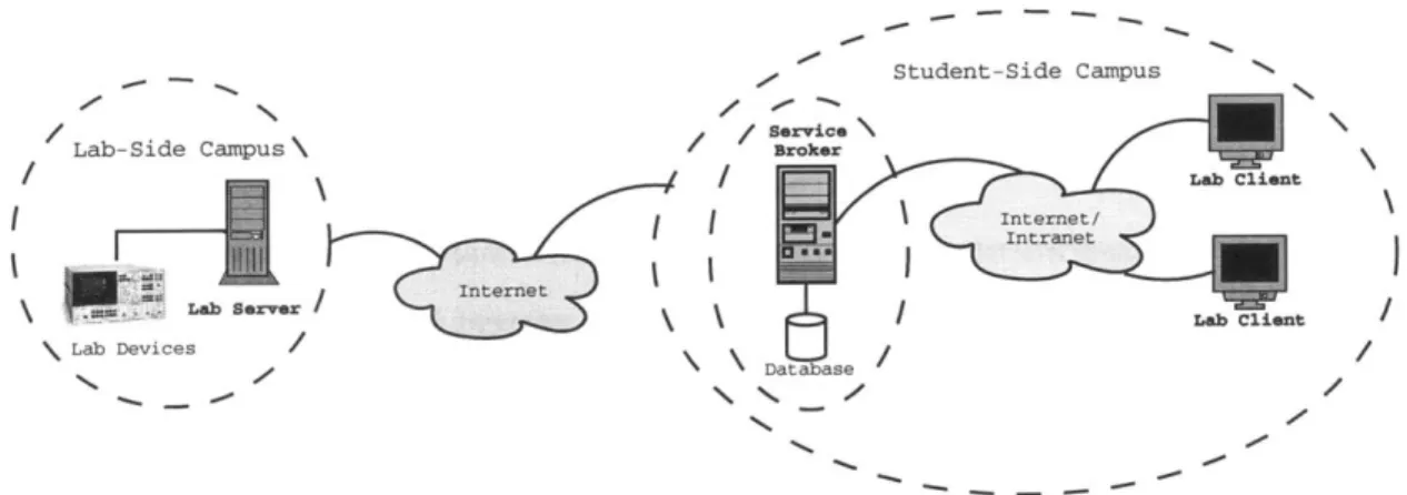
Student-Side Campus Lab-Side Campus L b Sovs Lab Devices N .0 / /servic4 Internet Databas / Lab Cliwnt e .00
Figure 2-1: Architectural overview of the three-tiered iLab system. The Service Broker handles all administrative tasks, thus freeing the Lab Server (and its developers) from having to implement custom administrative solutions for each different weblab. The Service Broker architecture also simplifies the sharing of iLabs between universities, by alleviating the lab-side (host) university from administering guest users. The host uni-versity can grant access to the student-side (guest) uniuni-versity's Service Broker, and the guest university can then administrate its own users.
once. They can also be used to generate archives of data gathered over extended
pe-riods of time. These data can then be employed at a later time for statistical analyses
and searches of events of interest.
Given the relative novelty of the iLab project, only the batched experiment
archi-tecture has been tested and fully deployed at the current time. The interactive and
sensor experiment architectures are still undergoing heavy development, and
proto-types should become available in 2005 and 2006 respectively [12].
2.3
The Batched Experiment Architecture
The iLab framework proposes a three-tiered topology for batched experiments based
on web services, as show in Figure 2-1:
1. The first tier consists of the Lab Client application that either runs as an
applet on the user's browser, or alternatively as a downloaded application on
the user's workstation.
2. The middle tier provides the shared common services by means of a Service Broker. The Lab Client communicates solely with the Service Broker, which forwards the requests to the final third tier. In the most common scenario, the Service Broker resides in the client side of the network, on a server at the student's institution. However, the architecture still allows for the Service Bro-ker and Lab Client to reside on different networks, for example, when granting accounts for users at other collaborating institutions.
3. The third and last tier is composed of the Lab Server, which usually resides at a specified laboratory site on campus. The Lab Server's task is to execute the experiments specified by users, notifying the Service Broker when their experiment has been completed and results are available to be retrieved.
In this framework, the Service Broker consists of completely lab-independent generic code, and knows nothing about the domain dependent nature of the experi-ments. On the other hand, the Lab Client and Lab Server constitute lab-dependent tiers that must understand and speak a common protocol for describing the experi-ment universe (e.g. when specifying experiexperi-ment parameters and results). Using this protocol, experiment requests and results are forwarded from Lab Client to Lab Server as opaque objects through the Service Broker. However, the Service Broker does not understand the contents of these opaque objects beyond the metadata description of experiment requests, such as Lab Server IDs, etc.
Furthermore, individual students are also abstracted away from the Lab Server, which does not know on which student's behalf it is executing a given experiment. Instead, the Service Broker authenticates and authorizes students to contact a par-ticular Lab Server, and then assigns them to an effective group when submitting an experiment specification on their behalf at the Lab Server. This scheme enables lab implementors to grant different levels of access to different effective groups, while delegating administrative decisions regarding group membership and management to the Service Broker. It also maintains the Service Broker as the single point of contact to the Lab Server, since students never need to contact or even be directly aware of
the location of the Lab Server.
2.3.1
The Case for Web Services
The choice of network technologies on which to build the iLab shared architecture has a great impact on the capabilities of the resulting distributed application framework. The iLab shared architecture favored the use of web services based on its design requirements emphasizing interoperability, software reuse, lab discovery and licensing possibilities [12].
First of all, it is crucial that the architecture support lab-side services as well as client-side services (including authentication and authorization, and experiment data storage). These two services will often run on separate networks, and possibly under different hardware and software platforms. Furthermore, the iLab architecture must be able to transparently support lab-side institutions which enforce different networking policies (firewalls and network services) from client-side institutions. Web services built on top of the SOAP [20] standard provide a platform and language-independent protocol for exchanging information in a decentralized and distributed environment. Moreover, SOAP web services are based on XML [21] and are adaptable to the Internet, since all communication takes place over the HTTP protocol. These advantages make web services a transparent and interoperable network technology ideal for the integration of iLab's distributed online laboratory framework.
Often, labs will possess a preexisting code-base that was independently developed by lab experiment owners and course staff. Web services makes it possible to leverage that previous development effort by reusing such legacy code when deploying these labs as iLab-enabled weblabs. In addition, the loose coupling of web services allows lab developers to more easily integrate vendor specific modules (e.g. National Instru-ments' LabView [22]) into their weblabs, thus potentially reducing total development time.
Looking at the future of the iLab project, web services technologies herald enor-mous possibilities in publishing and discovery methods for online services. Employ-ing web services WSDL [23] and UDDI [24] technology, weblab owners will be able
to publish their online labs services to the entire world, fostering the cooperation between educational institutions as more online labs become available. Moreover, WSDL-based negotiation will provide the possibility of matching Internet accessible labs with high-end visualization and data analysis tools licensed at the student-side institutions.
2.3.2
The iLab Batched Experiment API
In order for iLab-enabled weblabs to be truly distributed, the different layers must ad-here to the set of standardized operations stipulated in the iLab API. These operations are implemented over web services and the SOAP protocol for message exchange.
The iLab shared architecture defines two sets of web service methods composing the iLab API: service calls from Lab Client to Service Broker [25], and service calls
from Service Broker to Lab Server [26].
In fact, the bulk of the iLab API consists of pass-through methods, whose function is simply for the Lab Client to call a corresponding method from the Lab Server API. We summarize the most important ones here:
" GetLabStatus: checks on the status of the Lab Server.
" GetEffectiveQueueLength: checks on the effective queue length of the Lab Server.
" GetLabInf o: gets general information about a Lab Server.
" GetLabConf iguration: gets the lab configuration of a Lab Server.
" Validate: checks whether an experiment specification would be accepted if
submitted for execution.
" Submit: submits an experiment specification to the Lab Server for execution.
* GetExperimentStatus: checks on the status of a previously submitted exper-iment.
" RetrieveResult: retrieves the results from a previously submitted experiment.
In addition, the Service Broker publishes the Notify() web service method, which may be called by the Lab Server to announce that an experiment has been completed successfully and its results are ready to be retrieved.
2.3.3
Outline of a Student Batched Experiment Session
The following walk-through of a student experiment session illustrates the main in-teractions and web service calls between Service Broker, Lab Server, and Lab Client that take place during a batched experiment run [12].
1. First, the student must log on to the Service Broker through an active server
page, by supplying a user name and password for authentication.
2. The Service Broker responds by displaying a list of possible user groups for which the student is registered. Upon selecting one, the Service Broker displays a list of the available Lab Clients for the selected group.
3. Upon selection of a Lab Client, the corresponding Java applet loads on the
student's browser.
4. Using the Lab Client's user interface, the student edits the description of the experiment to be run at the laboratory site. Once complete, the student directs the Lab Client to invoke the web service Submit 0 method on the Service Bro-ker. Submit() takes a text encoded version of the experiment specification as an argument, which the Service Broker is not expected to understand.
5. The Service Broker then stores a copy of the experiment specification and
6. At this point, the Lab Server receives the experiment specification and validates
it for correctness. If legal, the Lab Server queues the experiment for execution. It then returns a submission report that includes an error message in the case of an invalid specification.
7. The Service Broker forwards the submission report to the Lab Client, along with
an experiment ID that is now used by all parties to identify the experiment.
8. Upon successful completion of the experiment, the Lab Server calls the Notify()
web service method on the Service Broker to indicate that the experimental re-sults are now available to be retrieved.
9. The Service Broker then requests the results from the Lab Server by means of
the RetrieveResult () web service call.
10. The Lab Server returns the experimental results and any error messages to the
Service Broker, which stores them but is unable to interpret them.
11. Finally, the Lab Client can request the cached results from the Service Broker by calling the RetrieveResult () web service. The Service Broker then returns
the results and any error messages, which the Lab Client is now able to interpret and display to the student.
Chapter 3
The Feedback Systems WebLab
This chapter describes the implementation strategy for the Feedback Systems
Web-Lab. First, the system architecture and its main components are briefly introduced.
We then define a common syntax and semantics for describing experiments and their
results between Lab Client and Lab Server.
3.1
Architecture Overview
The experiments composing the Feedback Systems WebLab are entirely specified by
the user before the experiment begins. Our WebLab thus falls into the batched
ex-periment category. Consequently, the architecture of the Feedback Systems WebLab
is based on the three-tiered batched experiment architecture described in Section 2.3.
The iLab architecture for batched experiments suggests a distributed system of
three layers for building the WebLab. These three tiers communicate with each other
via SOAP messages exchanged through web services, as shown in Figure 3-1. The
first tier is made up of the Lab Client, which runs on the user's machine as a Java
applet that can be loaded via a Java-enabled web browser. The Lab Client is the
only component in the system that is visible to the end user.
The middle tier consists of a trusted intermediary, known as the Service Broker,
which forwards requests from the Lab Client to the Lab Server for execution. The
main roles of the Service Broker are to authenticate users and grant them appropriate
permissions when forwarding their requests for experiments. The Service Broker also provides additional administrative services, such as group management, and the ability to temporarily store experiment requests from the Lab Client, and experiment results from the Lab Server.
Finally, the Lab Server constitutes the third tier in the architecture. Its task is to receive requests from the Lab Client via the Service Broker, and to reply to these requests also via the Service Broker intermediary. Usually, the Lab Client requests an experiment to run with a particular set of experimental parameters. In this case, the Lab Server communicates with the laboratory equipment, runs the experiment on the system under test, and finally replies with the experimental results upon successful completion of the experiment.
A detailed account of the Feedback Systems Lab Server implementation strategy is provided in Chapter 4, while Chapter 5 explains the design of our Lab Client. Both the Lab Server and Lab Client described in this thesis build upon the Feedback Systems WebLab prototype described in [27].
3.2
Describing the Experiment Domain
The iLab framework stipulates three different specifications for describing the experi-ment universe. The content of these specifications is unique to the Feedback Systems WebLab, and provides a common understanding of the experiment world between Lab Client and Lab Server. In addition, the Feedback Systems WebLab was designed in such a way that these specifications may reside anywhere on the World Wide Web. As a result, the experiment can be modified remotely by anyone with the appropriate permissions (for example, the appropriate teaching assistants and professors).
The three specifications defined by the iLab framework are the Lab Configuration, the Experiment Specification and the Experiment Result. Moreover, the Feedback
Systems WebLab introduces one additional specification: the Experiment Routine. In order to facilitate interoperability and the transfer of information across the Web, in-stances of these specifications are encoded using the syntax of the Extensible Markup
SOAP/HTTP SOAP/HTTP
inab
Internet Sevc rkrInternet
T SOAP/HTTP
SOAP/HTTP H 52
HP 3562A. Dynamic Signal Analyzer
Java-enabled Downloaded IIS Seger Experiment
Web Java Web Services Engine GPIB
Browser Applet USB
SQL Server
Lab Client LabJack System Under Test
Lab Server DAQ Board
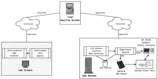
Figure 3-1: The Feedback Systems WebLab Architecture. The three-tiered architecture for the Feedback Systems Weblab consists of the Lab Client, the Service Broker, and the Lab Server. The Lab Client runs as a Java applet on the client's computer. The Service Broker provides generic weblab services for a variety of iLabs. Finally, the Lab Server communicates with the HP 3562A dynamic signal analyzer to set up frequency response measurements on the system under test. It can also set various command signals at the system under test via the LabJackTM DAQ board. All communication between tiers takes place using SOAP web service calls over HTTP.
Language (XML). XML also provides a useful way to store structured information and encapsulate it, making it easy for different computing systems to intercommunicate, as described in [21].
While actual instances of these specifications are encoded in XML, the actual structure of the specifications is defined by a corresponding XML schema written in the XML Schema language [28]. The XML schema thus defines the building blocks, consisting of elements and attributes and their underlying data types, that make up the specifications. An instance of a specification, however, contains the actual values for these elements and attributes, and must conform to the structure defined in the corresponding XML schema.
XML Schemas hold a number of advantages [29] over their predecessor DTDs [30]. For example, they are more easily maintained, support data types and name spaces, are extensible and modular, and are written entirely in XML. For these reasons, we
decided to convert our original specifications for the WebLab from the original DTD
definitions to ones using XML Schema.
3.2.1
Experiment Routine
The first of the specifications defined for the Feedback Systems WebLab is the
Ex-periment Routine. It must be noted that this specification is not defined by the iLab
framework, and thus plays no role within the Lab Server-to-Service Broker or Service
Broker-to-Lab Client APIs outlined in Section 2.3.2.
Why introduce yet another specification?
The reason why we decided to introduce this additional specification was to have
a single file through which to completely characterize any given experiment. As
described in Section 3.2.2, the Lab Configuration also serves the purpose of describing
experiment configurations. However, this specification is received at the Lab Client
and should thus be limited to client-specific information regarding the experiment.
On the other hand, we would also like to include information regarding other
experimental parameters necessary for the Lab Server to run the experiment on the
lab hardware. Such additional information does not need to and in fact should not be
made available to clients via the Lab Configuration. The Feedback Systems WebLab
thus introduces the notion of the Experiment Routine, containing both Lab Client
and Lab Server-specific information regarding an experiment, all encapsulated in a
single file.
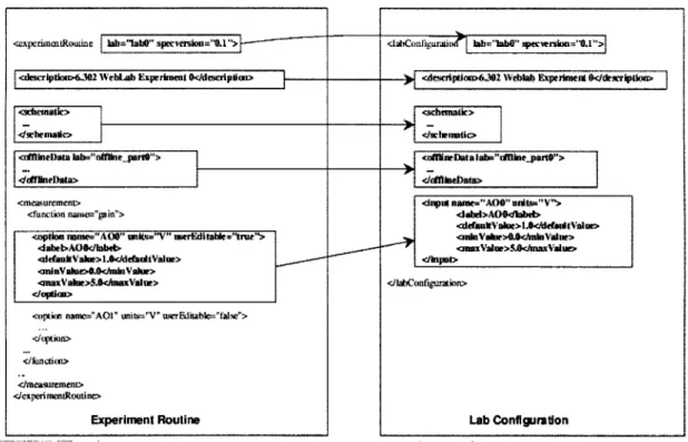
Moreover, for convenience and so that only one file need be edited by course staff
and system administrators, the Lab Configuration is dynamically generated from the
Experiment Routine at the Lab Server. In this way, Lab Client-specific information
can be safely handed to clients through the iLab API, while allowing the Lab
Server-specific experimental parameters to be hidden away from clients that need not or
should not be made aware of it.
Schematic +simpleImageURL: anyURI +detailedImageURL: anyURI Constraint +type: String +variablel: String +variable2: String Experiment Routine +lab: String
+specversion: Decimal Offline Data
+description: String
+schematic: Schematic * +name: String
+offlineData: Offline Data +label: String
+resultsURL: anyURI +initialization: Initialization +measurement: Measurement +constraint: Constraint Smeasurement J+function: Function nFunction
+name: String Option
+option: Option +name: Name
+units: Units
+userEdi table: Boolean +label: String +defaultValue: Decimal +minValue: Decimal +maxValue: Decimal
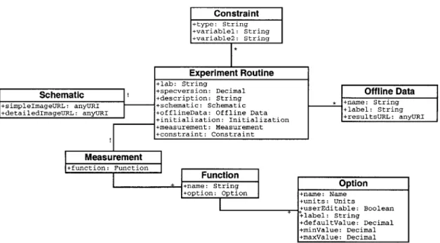
Figure 3-2: An object model representation of the Experiment Routine. The
Ex-periment Routine encapsulates a complete exEx-periment setup and measurement routine at the lab hardware. Thus, it defines the measurement parameters characterizing the experiment to be performed at the Lab Server. In addition, it provides links to the experiment's schematic diagram, and other generic lab-specific information such as the lab name and its description. Lab administrators also have the ability to provide exper-imental data for users to download via offline data, and can specify simple constraints
between measurement parameters.
Details of the Experiment Routine
As its name implies, the Experiment Routine is tightly bound to a particular exper-iment, and describes the set of experimental operations that need to be performed at execution time. The set of operations supported by WebLab experiments is di-rectly determined by the lab hardware employed at the Lab Server. Currently, the WebLab incorporates an HP 3562A digital signal analyzer in order to obtain the fre-quency response measurements on the system under test (SUT). In addition, the Lab Server can set input voltages to the SUT by communicating with a digital acquisition board over the USB port. Actual details of our lab hardware setup are provided in Chapter 4.
Reflecting the hardware capabilities, the Experiment Routine stipulates a set of initialization operations, defined by a measurement type and a measurement mode.
The measurement type defines the kind of measurement operation to be performed by the dynamic signal analyzer, and can be one of frequency response or time response. Similarly, the measurement mode describes the type of response to be measured by the signal analyzer from linear response, log response, and swept sine. These experimental settings constitute the bulk of Lab Server-specific experiment information that is
hidden from clients.
In addition, the Experiment Routine also specifies a set of measurements that are used to fine-tune the experiment to be run at the lab hardware. These measurements are divided into one of the following different functions:
e Gain: this function contains options to set command signals on the system under test.
* Source: sets the option for the source level at the signal analyzer.
e Frequency: this function contains the options to set the start and stop fre-quency, as well as the sweep rate for the measurement on the signal analyzer. Moreover, each of these options can be made visible to clients via the Lab Con-figuration by setting the userEditable attribute to true. Any other options that are not set to true will be hidden from clients by default.
Finally, the Experiment Routine also contains generic information regarding the experiment, such as the lab's internal name, a descriptive label for the experiment, and URL pointers to simple and detailed experiment schematic diagrams. The Exper-iment Routine may also contain information regarding offline data, used to provide access to experimental data that have been previously collected and are available for clients to download at their convenience.
Offline data are characterized by generic experiment information, including a unique lab name, a descriptive label, as well as a URL pointer to the Web location where the experimental results can be retrieved. This generic information describing experiments is also part of the Lab Client-specific data that makes up the Lab Config-uration, and described in more detail in Section 3.2.2. An object model representation of the Experiment Routine is given in Figure 3-2.
Lab Client
ad ent a e GetLabConfiguratloi loads requesting
LabConfiguration
LabClint ppit~ Return
Laa a bpolet nfiguration Ui components LabConfiguration D Retrieve default Lab Swr~ ExperimentRoutine GetLabConfiguration Database Retu n N ExperimentRoutine URL Retrieve ExperimentRoutine contents LabConfiguratlon frm ExperimentRoutinp Returm ExperimentRoutlne XML data
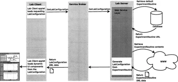
Figure 3-3: Sequence of steps involved in the dynamic generation of the Lab Configura-tion from the Experiment Routine. First, the Lab Client requests the Lab ConfiguraConfigura-tion from the Lab Server via a GetLabConf iguration web service call to the Service Broker. The Lab Server's web service logic then retrieves the URL for the default Lab Routine from the Lab Server database, and fetches its contents from the web locker. Lastly, it generates the Lab Configuration from the Experiment Routine data as outlined in Figure 3-4, and forwards it to the Lab Client via the Service Broker.
3.2.2
Lab Configuration
As mentioned in Section 3.2.1, the Lab Configuration is dynamically generated at
the Lab Server based on the Experiment Routine. Figure 3-3 depicts the complete
sequence of steps involved in loading the Lab Configuration at the Lab Client, while
Figure 3-4 demonstrates how the Lab Configuration is populated from the Experiment
Routine at runtime by the Lab Server.
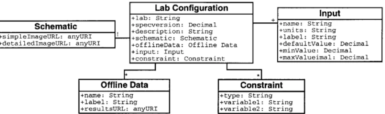
The Lab Configuration consists of all the Lab Client-specific information
regard-ing an experiment, and contains generic configuration information for the experiment
requested by the Lab Client. More specifically, it lists the set of inputs to the
experi-ment that can be modified at the Lab Client, along with their default values and valid
ranges. In addition, it provides some generic information concerning the experiment,
such as a text description, and URL pointers to the experiment's simple and detailed
schematic diagrams. As with the Experiment Routine, the Lab Configuration may
also contain information regarding offline data. Figure 3-5 provides an object model
I I
Figure 3-4: Dynamic generation of the Lab Configuration from the Experiment
Rou-tine. The Lab Configuration is not a stand-alone specification but is instead completely derived from the Experiment Routine by the Lab Server. It consists of generic lab information such as the lab description, the schematic diagram, offline data and mea-surement constraints. In addition, it contains all those meamea-surement options marked as
userEditable in the Experiment Routine.
representation of the Lab Configuration.
3.2.3
Experiment Specification
The Experiment Specification is prepared by the user at the Lab Client end, and rep-resents the parameter values constituting the user's particular run of the experiment. An instance of the Experiment Specification contains a collection of inputs consisting of the parameter name and units, along with the value for the parameter provided by the user. An object model representation of the Experiment Specification is given in Figure 3-6.
<xperimtR ouune Jab I ab" spverio=".1"
<descrIptui6J02 WebLab Expirimemi <desripNu>
imideuta > I
.cihwatta bb- "ofie vr0">
<meaurement> <functkn naWe="Pin">
<option nne="A00" units="V" merEdta."trUe"> dabeb.AOOEabd> <defaukVakw>lA</ddamdtVaue> .aniVakie>.U</mInVakr> <maxVabie>S.chnaxVaue> <]option> </qflon> fUnctim> </measuremen=* 4expenmentRoutine> Experiment Routine a ndgu~zI~iLraio~i M lbb0" SpecwVreion="1">
<daxcrlptiom>6.3V2 Webdb Experkment k</dexcriptiouw
<schmeatk> </GnineDat3> dnpw naune="AOO" utas="V"> <ah4d>AO$4kbd> <dda~uVals>l</deAmitV31w> <ndVaue>0<MihnVaae> <maxValue>5.0mnaxVadue> </knpty Lab Configuraon> Lab Configuration
+simpleImageURL: anyURI +detailedImageURL: anyURI
K
Offline Data +name: String +label: String +resultsURL: anyURIInput
I
+-+name: String +units: String +label: StringData +defaultValue: Decimal +minValue: Decimal nt +maxValueimal: Decimal Constraint +type: String +variable: String +variable2: String
Figure 3-5: An object model representation of the Lab Configuration. The Lab Con-figuration encapsulates all Lab Client-specific information regarding an experiment. It consists of generic lab information such as the lab description, the schematic diagram, offline data and measurement constraints. In addition, it contains all those measurement options that lab administrators have defined to be user-settable by the Lab Client.
Experiment Specification +lab: String +specversion: Decimal +input: Input Input +name: String +units: String +value: Decimal
Figure 3-6: An object model representation of the Experiment Specification. The
Experiment Specification consists of a number of input parameters making up a user's experiment request to be run at the lab hardware. This specification is usually generated at the client side after users submit their experiments from the Lab Client.
3.2.4
Experiment Result
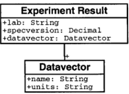
Once the experiment has completed successfully, the Lab Server produces a list of data vectors containing the measured results and encapsulates them in the Experiment Result. Each data vector is characterized by its result type (usually one of frequency, phase or magnitude), the units for its data values, and the list of comma-separated numeric values measured by the experiment hardware. Figure 3-7 provides an object model representation of the Experiment Result.
Schematic Lab Configurat +lab: String +specversion: Decimal +description: String +schematic: Schematic +offlineData: Offline +input: Input +constraint: Constrai ion
Experiment Result
+lab: String +specversion: Decimal +datavector: DatavectorDatavector
+name: String +units: StringFigure 3-7: An object model representation of the Experiment Result. The Experiment
Result encapsulates the experimental data retrieved after successfully completing an experiment request at the Lab Server. It consists of a list of data vectors, usually of types frequency, gain and magnitude. Each of these data vectors is further characterized
Chapter 4
The Feedback Systems Lab Server
4.1
Architecture
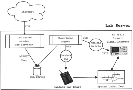
The Lab Server implements the iLab framework's Lab Server API using web services under Microsoft's ASP .NET. The web service is implemented in the Visual Basic .NET language on a web server running Internet Information Services (IIS), and can be invoked through a fixed URL reserved for the Feedback Systems WebLab. The Lab Server also runs an SQL database under Microsoft SQL Server 2000. This database is accessed from the web services module for authentication and authorization, logging calls to the web service, retrieval of hardware information relating to the experi-ment, etc. In addition, the database is used to enqueue experiment requests and to temporarily store any experimental results that were processed at the Lab Server.
The Lab Server also runs an experiment engine on its own thread, separate from the web services module. The experiment engine periodically checks the queue of submitted experiments, and retrieves the job with highest priority or the first one in the queue. It then processes the experiment specification provided by the user at the Lab Client, and sets up the hardware appropriately. This step is accomplished by communicating with an HP 3562A digital signal analyzer over the GPIB bus, and whose probes are attached to the system under test. Moreover, our current setup also makes use of a 20 output data acquisition and control (DAQ) board allowing users to set inputs to the system under test [31]. The DAQ board inputs are set
Internet
HTTP Lab Server
Figure 4-1: Lab Server architecture overview. The Lab Server is composed of three main
modules running concurrently. First, the ASP.NET worker process listens for incoming web service method calls and dispatches them to the appropriate class and method. Sec-ond, the Lab Server maintains an SQL database storing experiment configurations and requests, user management and lab resource allocation information. Finally, the Exper-iment Engine executes any pending experExper-iments on the lab hardware. It communicates with the HP 3562A dynamic signal analyzer to set up frequency response measurements, and can also issue various command signals to the system under test via the LabJack
DAQ board for further experiment customization.
by the experiment engine, which makes calls to a dynamic link library providing
communication with the DAQ board over the USB interface. Figure 4-1 provides a
diagrammatic representation of the main Lab Server components.
4.2
ASP.NET Web Services Architectural Overview
The current section provides a brief introduction to the internals of ASP.NET, the
web service implementation chosen for our Lab Server.
Like all web services implemented in ASP.NET, our Lab Server web service is
accessible over the HTTP transport protocol [32]. When an incoming HTTP message
reaches port 80, Internet Information Server (IIS) maps web services asmx extensions
HP 3562A
IIS Server Experiment USB Dynamic
running Engine Agilent Signal Analyzer
Web Services USB I DLLs
ASPNET Labiack
GPIB
User DLL
SQL Server Bm
to AspneLisapi.dll by default [33]. As a result, web service HTTP requests can be forwarded to a separate worker process named Aspnetwp.exe, hosting the common language runtime and the .NET HTTP pipeline.
When a message enters the .NET HTTP pipeline requesting an asmx file, the pipeline calls the WebServiceHa ndlerFactory class to instantiate a new WebServiceHandler object to process the request. The WebServiceHandler object then opens the physical
asmx file to determine the name of the class that contains the web methods composing the web service.
Moreover, the ASP.NET web services model assumes stateless service architecture, and therefore does not inherently correlate multiple calls from the same user. In fact, each time a client invokes an ASP.NET web service, a new object is created to service the request. This object is then destroyed after the method call completes.
Once the asmx handler is called by the .NET HTTP pipeline, it can begin to take care of the XML, XSD, and SOAP processing. The asmx handler carries out the tasks of message dispatching and of mapping XML to objects. In message dispatching, the asmx handler first resolves the referenced .NET class by looking at the WebService declaration found in the asmx file. It then reads the SOAP-encoded information in the incoming HTTP message to determine exactly which method to call in the referenced class. Through .NET reflection, it uses the value of the SOAPAction header to determine how to dispatch the message to the corresponding web method.
Before it can actually invoke the method, however, it needs to map the incoming XML into .NET objects.
The asmx handler maps XML to .NET objects by inspecting the class via reflection in order to determine how to process the incoming XML message. It is the job of the XmlSerializer class to perform the automatic mapping between XML and .NET objects in the System. Xml. Serialization namespace, as shown in in Figure 4-2. At this point, the web method can be called and its results serialized back into an XML
(
Class)ctiema
Figure 4-2: Mapping XML to .NET objects [33]. Before the asmx handler can actually invoke the method it needs to map the incoming XML into .NET objects. It is the job of the XmlSerializer class to perform the automatic mapping between XML and .NET objects in the System.Xml.Serialization namespace.
4.2.1
Security
Since ASP.NET is based on HTTP, it becomes possible to leverage the security
fea-tures available in IIS to provide strong support for standard HTTP authentication
schemes. More specifically, the Feedback Systems Lab Server makes use of IP
filter-ing to deny access to the WebLab service from all hosts except the trusted Service
Broker. In addition, all connections between Lab Server and Service Broker can be
further secured using the Secure Sockets Layer (SSL) protocol. As a result, any data
exchanged between these two hosts does not travel as cleartext but instead is always
encrypted prior to being sent over the wire.
Beyond the lab-specific security considerations outlined above, the iLab framework
also provides a simple mechanism based on SOAP headers for authentication. When
the Lab Server becomes registered at the Service Broker, the latter assigns it a passkey
that is bound to that Lab Server's unique ID (see Section C.1). Similarly, when the
Lab Server registers the Service Broker, it too assigns the latter a passkey bound to
the Service Broker's unique ID. From this point on, all communication between Lab
Server and Service Broker includes a SOAP header parameter containing the passkey
for the corresponding host. This mechanism, when used along with SSL to encrypt the
payload contents, ensures that only registered hosts are able to successfully execute
web service methods on either Lab Server or Service Broker.
4.3
Database
In addition to Microsoft's IIS, the Feedback Systems Lab Server runs SQL Server 2000 for experiment data and configuration management. The SQL server can be accessed by both the web services module and the experiment engine at any given time. It consists of SQL tables used to encapsulate Service Broker and Lab Server configurations, experiment records, and group management, as well as of a number of procedures used to manipulate them.
For instance, the LSSystemConfig table stores laboratory hardware configuration data, including the bus address for the signal analyzer and its internal VISA name. It also encapsulates all Lab Server specific information, such as the Lab Server's unique ID and the default experiment routine that it should run. In addition, it contains a boolean flag exp-eng-is-active which is automatically set to true whenever the experiment engine is running, but which is set to false otherwise. This mechanism allows the Lab Server to gracefully reject experiment requests at those times when the experiment engine is not running.
Similarly, the Brokers table is used to store data pertaining to Service Brokers registered at the Lab Server. Therefore, it contains information such as the Service Broker's ID, the Service Broker and Lab Server authentication passkeys, and the URL for the Service Broker-to-Lab Server web service interface. These parameters and their use are described in further detail in Section C.1.2.
Experiment routines are also conveniently abstracted in the SQL database, where they are stored in the LabRoutines table. Each experiment routine is uniquely iden-tified by a lab name, and consists of a pointer to the routine's URL and an optional description. This scheme makes it very simple for WebLab administrators to define and support a variety of experiments. Different experimental setups can be written at any time, and registered at the LabRoutines table. It then becomes trivial to up-date the currently running experiment, by simply updating the default experiment routine reference to the new routine in the LSSystemConfig table described above. In the case of the 6.302 WebLab, these changes can be easily achieved through a set of
administrative GUI applications that interface to the underlying Lab Server database.
Group management is also managed through the database. Groups are
character-ized by a unique group-id, the name of the corresponding Service Broker group, and
the respective Service Broker ID. In addition, a class-id is used to manage class-based
resource permissions (through the ClassToResourceMapping table) and to implement
a simple prioritization scheme.
Moreover, the database is the key mechanism used to handle incoming experiment
requests. Each experiment job is encapsulated in the JobRecords table, where it is
tagged with status information such as "QUEUED", "IN PROGRESS",
"COM-PLETED", or "CANCELLED". The status information can then be used along
with priority and group membership information to implement a first-in first-out
queue of jobs ordered by priorities. The group membership information also ensures
that job owners have the necessary permissions for the Lab Server to satisfy their
experiment requests.
The JobRecords
table
also contains all other ancillary information relating to
ex-periment jobs, such as the elapsed and estimated execution times, times of submission
and completion, and queue information. Furthermore, it stores the experiment
re-quest itself in the form of the experiment specification sent from the Lab Client, as
well as the lab configuration information for the current experiment. It also contains
the experiment results in the case that the experiment has been successfully
com-pleted at the Lab Server. If an error occurs and the experiment is not executed to
completion, an error-message is stored as part of the job record.
Finally, the WebLab is dependent on the database for logging and auditing
pur-poses. All incoming and outgoing web service calls are written to the
WebMetho-dRequestLog table. These entries can then be examined at any time for security,
debugging and WebLab usage evaluation purposes.
A design decision that emerged was the mechanism for communicating between
the web service and the database. Initially, the web service accessed SQL Server with
explicit credentials, by defining a special user on the Lab Server with permissions to
log in to the database. Although this method has the advantage that the database
server need not be present at the local host, it requires that a password be generated and included as plaintext inside the source code. For this reason, the current im-plementation accesses the database using Windows Integrated Security [34], via the
ASPNET user reserved to web applications.
4.4
Experiment Engine
4.4.1
Preparing the Experiment
The Experiment Engine executes on a separate thread from the Lab Server web service and has the task of running experiment jobs submitted to it through the iLab interface. When the web services thread receives an experiment job via the Submit web service method, the experiment request in the form of an Experiment Specification is queued at the Lab Server's database.
When the Experiment Engine is running, it periodically queries the database ev-ery five seconds to check for incoming experiment requests from users. If the Lab Server's experiment queue contains any pending experiments, an experiment request is selected from the queue in a first-in first-out basis after ordering the jobs in de-scending order of priority. Each time an experiment request is selected to be run at the Experiment Engine, it is labeled as "IN PROGRESS" in the Lab Server's database.
The list of experiment operations to be executed on the lab hardware for this experiment job is then loaded at the Experiment Engine. The instructions for running the experiment are obtained by parsing the Experiment Routine for the current lab, whose location is stored on the Lab Server's database. The Experiment Routine can reside on any world-readable web address (e.g. in the 6.302 Athena locker), which makes it easy to maintain and modify remotely by 6.302 course staff and WebLab administrators. Furthermore, it is now possible to easily switch from one experiment to another (e.g. when changing from one lab assignment to the next) by creating more than one Experiment Routine files and simply updating the current lab pointer
![Figure 4-2: Mapping XML to .NET objects [33]. Before the asmx handler can actually invoke the method it needs to map the incoming XML into .NET objects](https://thumb-eu.123doks.com/thumbv2/123doknet/14680378.559113/38.918.345.653.117.284/figure-mapping-objects-handler-actually-invoke-incoming-objects.webp)
![Figure 4-3: Server-side hardware configuration (taken from Isaac Dancy [31]). The four command signals (AOO-AO3) issued to the system under test can be set from the Lab Server via the LabJack](https://thumb-eu.123doks.com/thumbv2/123doknet/14680378.559113/43.918.185.705.123.404/figure-server-hardware-configuration-command-signals-server-labjack.webp)