Design of Educational Engineering Projects Fabricated with the Laser-Cutter and CNC Wire Bender by
Larkin V. Sayre
Submitted to the
Department of Mechanical Engineering
in Partial Fulfillment of the Requirements for the Degree of Bachelor of Science in Mechanical Engineering
at the
Massachusetts Institute of Technology June 2017
2016 Massachusetts Institute of Technology. All rights reserved.
Signature redacted
Signature of Author: Certified by: Accepted by: MASSACHUSETTS INSTITUTE OF TECHNOLOGYAUG 29 2017
LIBRARIES
Department of Mechanical Engineering December 15, 2016
Signature redacted
Steven B. Leeb
Professor, Electrical Engineering and Mechanical Engineering Thesis Supervisor
Signature redacted
Rohit Karnik
Professor of Mechanical Engineering Undergraduate Officer
Design of Educational Engineering Projects Fabricated with the Laser-Cutter and CNC Wire Bender by
Larkin V. Sayre
Submitted to the Department of Mechanical Engineering on December 15, 2016 in Partial Fulfillment of the
Requirements for the Degree of
Bachelor of Science in Mechanical Engineering
ABSTRACT
The aim of this investigation is to design educational project enclosures for engineering students at MIT that utilize the laser-cutter, CNC "DiWire" wire bender and various other mechanical engineering tools. Introducing students to the laser-cutter and wire bender gives them hands-on experience with some exciting mechanical tools for fabrication to supplement their courses in electrical engineering.
The key objective of this investigation is finding a cheap, safe, professional-looking, easy-to-manufacture setup that teaches students the desired concepts and gives flexibility for Professor Leeb to integrate novel engineering projects into his classes.
The second section of this design project is the creation of a soldering iron holder made using components bent on the DiWire. Many design iterations are carried out before settling on the final design and material choice. The soldering iron holder is then incorporated into a larger electrical engineering project. This larger project is a speaker that students put together and house in a special enclosure.
Thesis supervisor: Steven B. Leeb
Acknowledgements
I would like to thank Professor Leeb for his great ideas, guidance and patience as my supervisor throughout this project. I would also like to thank Dave Lewis and the EDS staff for helping me with machine operation and providing lots of great advice.
Thanks also go to Dan Kelly for his original design of the speaker project that I have adapted for this thesis and to the staff at Pensa Labs who helped me as I was leaming to use the DiWire machine.
Table of Contents
A BSTRA CT ... 3
Acknow ledgem ents ... 4
Table of Contents ... 5
List of Figures ... 6
List of Tables...8
1. Introduction ... 9
2. Design Inspiration - The Current Speaker Project Setup... 10
3. D esigning N ew Project Boxes...12
3.1. Laser-cutting Ham m ond Boxes... 16
3.2. Laser-cutting Custom Lids ... 17
3.3. Further Options...28
4. CN C W ire Bender Project...30
4.1. D iW ire Learning Objectives ... 32
4.1.1. Plastic Deform ation of M etal Rods ... 33
4.1.2. M etal Spring-Back and D iW ire Calibration... 34
4.1.3. Joinery ... 35
4.1.4. D iW ire Accessories... 36
4.2. Designing the Soldering Iron Holder ... 38
4.2.1. Acrylic Base Design... 38
4.2.2. Continuous W ire Design ... 40
4.2.3. Clip Joinery Design... 42
4.2.4. Interlocking Supports Design... 43
4.2.5. Final Soldering Iron Holder Design Choice... 46
4.3. Integrating the Soldering Iron Holder w ith the Project Boxes ... 47
List of Figures
Figure 1: SolidWorks assembly of the original speaker setup that is currently used...10
Figure 2: SolidWorks assembly of the original speaker setup with the thermoform casing suppressed to show the internal structure of the speaker design...10
Figure 3: The original speaker setup (top view)...11
Figure 4: The original speaker setup (side view)...11
Figure 5: SolidWorks drawing showing the outer dimensions of the thermoformed piece (in inches)...13
Figure 6: SolidWorks Assembly of the proposed setup, the bright colors are added artificially to highlight the different parts... . . 14
Figure 7: SolidWorks model of the thermoformed piece, the real thermoformed part will be off-white instead of p in k ... . .... 14
Figure 8: SolidWorks model of the laser-cut part that will attach the thermoformed part to the lid, the real part will be black instead of blue... 15
Figure 9: SolidWorks part showing the outline that will be cut into the top of the box lids...15
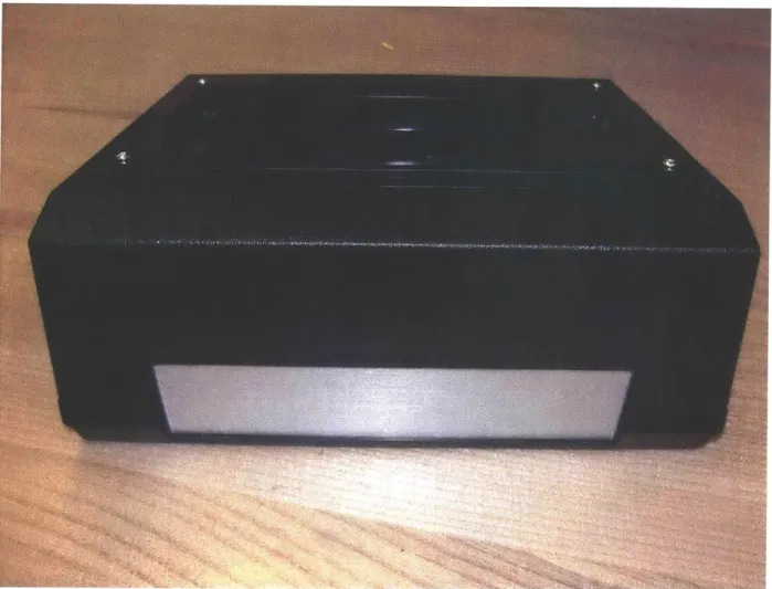
Figure 10: Laser-cut Hammond ABS box with clear acrylic covering attached with 4-40 screws...16
Figure 11: Laser-cut Hammond ABS box with clear acrylic covering attached with 4-40 screws with lid and base sep arated ... . . 17
Figure 12: Disassembled view of first acrylic lid design...18
Figure 13: Assembled view of sloped lid design...19
Figure 14: View of the back of the sloped lid design...20
Figure 15: Top view of the disassembled box without laser-cut attachments...20
Figure 16: Top view of half of the ABS box (right) and its laser-cut acrylic lid (left)...21
Figure 17: Full prototype of the ABS box including acrylic lid and acrylic outline to hold thermoform in place...22
Figure 18: Top view of the disassembled metal box design...23
Figure 19: Close-up of the holes used for attaching the three components together...23
Figure 20: Assembled metal box design with fully acrylic lid and thermoform attachment piece...24
Figure 21: Disassembled view of the missing panel metal box design...25
Figure 22: Assembled missing panel metal box design with integrated soldering iron holder...26
Figure 23: Side view of assembled missing panel metal box design...26
Figure 24: Close-up of the clear acrylic side-panel option...27
Figure 25: O riginal fully acrylic lid design...28
Figure 26: Fully acrylic lid design with thermoform moved to the center...29
Figure 27: Fully acrylic lid design with thermoform rotated and moved to corner...29
Figure 28: Photo of the DiWire used for this project...30
Figure 29: Close-up of the DiWire bend head and rollers for extending the rods...31
Figure 30: 3 views of a 3 inch diameter spiral bent on the DiWire as a preliminary test...32
Figure 31: Graphic of the von Mises stress in a 2" long, 1/8" diameter aluminum bar when deformed under 20N of fo rc e ... 3 3 Figure 32: Graphic of the displacement in a 2" long, 1/8" diameter aluminum bar when deformed under 20N of fo rce ... 3 4 Figure 33: Photos from the DiWire website' that show some clever use of laser-cut joinery...35
Figure 34: Photos from the DiWire website that show plastic joinery produced by Pensa Labs...36
Figure 35: photo from the DiWire website that shows the metal universal clips produced by Pensa Labs...36
Figure 36: photos showing the laser-cut ramp interfacing with the DiWire...37
Figure 37: 3 views of the acrylic base design for a soldering iron holder...38
Figure 38: Close-up of the bent wires before insertion into the acrylic stand...39
Figure 39: 3 views of an alternate acrylic base design...39
Figure 40: Photo of the continuous wire design...40
Figure 41: Alternate view of continuous wire design...41
Figure 42: C lip joinery design ... 42
Figure 43: C lose-up of clip joinery design...43
Figure 44: Assembled view of interlocking supports design (left) and disassembled view (right)...43
Figure 45: Interlocking supports design with adjustable metal clip attachment...44
Figure 46: Intended placement for soldering iron in interlocking supports...45
Figure 47: Soldering iron slippage when placed in interlocking supports...46
Figure 48: Cleaning wool pot to be integrated into the soldering iron holder project ... 47
Figure 49: Soldering iron holder and wool pot integrated into the missing panel metal box design...48
List of Tables
Table 1: Bill of materials for the Hammond box design... 17
Table 2: Bill of materials for the sloped lid design...21
Table 3: Bill of materials for the ABS box design...22
Table 4: Bill of materials for the metal box design...24
Table 5: Bill of materials for the missing panel metal box design...27
1. Introduction
MIT aims to educate students with the "Mind and Hand" approach. This means thorough theoretical instruction integrated with hands-on fabrication and "learning by doing". Project classes at MIT in the electrical engineering curriculum often lack aspects of mechanical fabrication. By introducing mechanical build projects to electrical engineering classes, students can be introduced to another facet of engineering. Professor Steven Leeb (of the MIT Laboratory for Electromagnetic and Electronic Systems) runs a class in which students put together a speaker using thermoformed and laser-cut components that house the electronics. This project (designed by Dan Kelly) integrates some great mechanical fabrication tools such as the laser-cutter and thermoform machine with an interesting electronics component. However,
feedback from students taking the speaker project class was that they wanted more hands-on aspects to the building. The current setup is simply put together by the students since all the components are pre-made. To further encourage mechanical fabrication, this thesis project expands on the speaker project from Professor Leeb's class and integrates a project on the DiWire machine which is a CNC wire bender into the speaker enclosure.
2. Design Inspiration
-
The Current Speaker Project Setup
Figure 1: SolidWorks assembly of the original speaker setup that is currently used, designed by Dan Kelly
Figure 2: SolidWorks assembly of the original speaker setup with the thermoform casing suppressed to show the internal structure of the speaker design
-A
Figure 3: The original speaker setup (top view)
3. Designing New Project Boxes
The goals of this project are to use the pre-existing thermoform piece shown in figures 3 and 4 and find a way to integrate it into a larger enclosure (greater depth and extendable length). The first step is to prototype many different options for box enclosures then identify the best option for students. A simple solution to the problem would be to make fully laser-cut boxes with inter-locking fingerjoints. This is not a great option however since it would require a huge amount of time spent laser-cutting and assembling boxes. Therefore the first avenue of investigation is to purchase a variety of boxes and laser-cut directly into their lids (if possible) to provide the attachment holes. This would in theory significantly decrease the manufacturing steps for this class and allow students to focus on the steps that are teaching the crucial concepts and skills. The challenge with this approach is finding cheap boxes with the correct dimensions and material properties. ABS is a candidate for laser-cutting and it is laser-cut in one of the currently used EDS (Engineering Design Studio at MIT) projects after being thermoformed. Unfortunately, some laser-cutter operators recommend against cutting ABS because it can catch fire more easily than other materials and it produces some nasty fumes. Laser-cutting ABS boxes made by Hammond Manufacturing has been successful for past projects in Professor Leeb's classes so attempting to cut their boxes makes up the first design iteration.
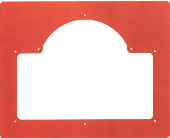
Figure 5 shows the outline of an acrylic part that I am planning to use to hold the thermoformed piece in
place over the top of the enclosure. This part was designed using the CAD of the thermoformed part which was created by Dan Kelly This acrylic part will fit over the protruding part of the thermoform and cover up the jagged edges that result from cutting the thermoformed plastic down to size. This is the same technique used in the original speaker setup except the bottom acrylic plate will be replaced by a
__________ 1
shown in figure 5 show the edges of the acrylic piece which are the dimensions that dictate the minimum size of the enclosure that can be placed underneath.
K
4-
+
.1O
8.88
Figure 5: SolidWorks drawing showing the outer dimensions of the thermoformed piece (in inches)
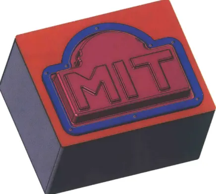
Figure 6: SolidWorks Assembly of the proposed setup, the bright colors are added artificially to highlight the different parts
Figure 7: SolidWorks model of the thermoformed piece, the real thermoformed part will be off-white instead
Figure 8: SolidWorks model of the laser-cut part that will attach the thermoformed part to the lid, the real part will be black instead of blue
3.1. Laser-cutting Hammond Boxes
After a thorough search, it turns out that Hammond Manufacturing does not have a large selection of ABS boxes or boxes in other materials that can be laser-cut. Ideally the enclosures purchased for this project would be in three sizes: one that just fits around the thermoformed piece (roughly 7"x9"), one that extends a few inches out on one side for a small additional component (roughly 7"x12") and one that extends further out to accommodate a larger addition (roughly 9"x16"). Hammond does manufacture one enclosure that fits the smallest desired dimension (7"x9").
Figure 11: Laser-cut Hammond ABS box with clear acrylic covering attached with 4-40 screws with lid and base separated
Figures 10 and 11 show the successful laser-cutting of a smaller Hammond box that would work to fulfil the smallest desired dimension. Unfortunately, larger Hammond boxes are not in laser-cuttable materials
(e.g. die-cast aluminum) and are prohibitively expensive. Note: the acrylic outline for securing the thermoform is shown here in clear acrylic but it will be cut in opaque acrylic in the real project.
Table 1: Bill of materials for the Hammond box design
Part Quantity Price Part Number Source
Hammond box (9.843" L x 1 11.27 HM1099-ND Digikey
7.087" W)
.125" thickness acrylic sheet 1 5.73 44441 United States Plastic Corp.
4-40 V2" machine screw 8 4.45 for 100 91772A1 10 McMaster
4-40 hex lock nut 8 4.07 for 100 91831A005 McMaster
3.2. Laser-cutting Custom Lids
Since Hammond boxes do not come in the correct dimensions while also being of a laser-cuttable
material, the next step is to come up with alternate solutions. One such solution is to order boxes, remove the lids and replace them with fully acrylic lids that can hold the thermoformed piece and can also be cut into to add further projects. These acrylic lids must have custom attachment holes cut into them to
interface with the box underneath. Using this approach removes the requirement that the purchased box be laser-cuttable which significantly improves flexibility in the design. The figures in this section show the prototypes of boxes with their lids removed and with custom lids attached.
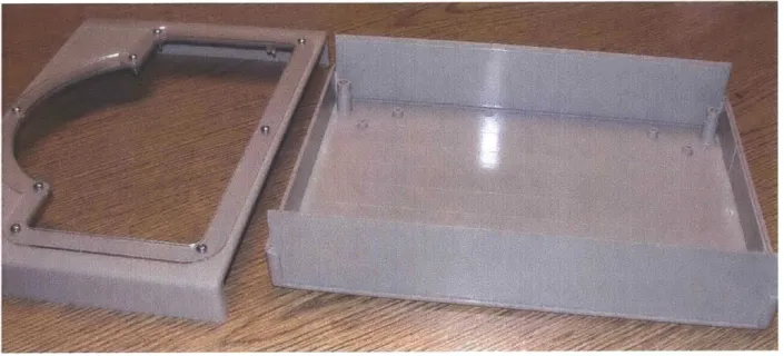
Figure 12: Disassembled view of first acrylic lid design
The design above consists of a sloped-lid box that splits into two halves and two laser-cut acrylic pieces that sandwich the thermoformed piece between them. The acrylic pieces are attached to the sloped surface (upper left of figure 12) with " 4-40 screws. The bottom base of the purchased box (upper right of figure 12) has plastic standoffs on its inner surface which could be useful for mounting electronics. This design is too small for incorporating more projects onto its surface which means it would work solely to house the speaker project.
Figure 13: Assembled view of sloped lid design
Figure 13 shows the assembled sloped lid design including the 4-40 screws that attach the acrylic plates to the box's surface. The downside of this design is that it still requires a decent amount of laser-cutting
since it needs two plates to hold the thermoform. The advantage of this design over the original speaker setup is the extra space provided within the enclosure.
Figure 14: View of the back of the sloped lid design
Figure 15: Top view of the disassembled box without laser-cut attachments
Table 2: Bill of materials for the sloped lid design
Part Quantity Price Part Number Source
Sloped lid box 1 21.62 616-62291-510-000 Mouser
4-40 %" machine screw 4 4.95 for 100 91772A 113 McMaster
.125" thickness acrylic sheet 1 11.46 44449 United States Plastic Corp.
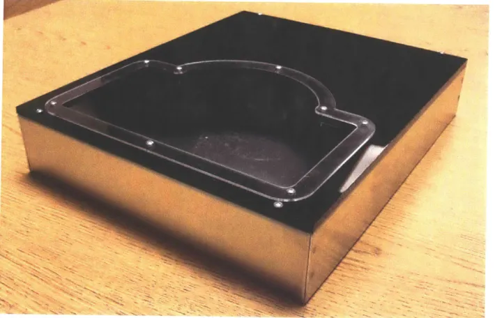
The next prototype uses an ABS box with larger dimensions (approximately 9" x 12"). This box is in two equally sized halves that screw together with M4 standard screws. One side of the enclosure has tapped holes and the other has clearance holes. Figure 16 below shows one half of the box on the right and the acrylic lid that was designed to fit flat on top. The blank acrylic above where the thermoform attaches can be used for further projects which is an advantage to this design.
Figure 16: Top view of half of the ABS box (right) and its laser-cut acrylic lid (left)
1A
Figure 17: Full prototype of the ABS box including acrylic lid and acrylic outline to hold thermoform in place
Figure 17 shows the full setup that makes use of 20mm M4 screws at the four corners to fasten the lid and
2" 4-40 screws with locknuts to fasten the thermoform outline. During testing it became clear that 20mm
M4 screws would actually work with both sides of the box since the side without tapped holes has a thinner region that the screws can bite into and therefore hold the lid on rigidly. This is a big advantage to this design as it therefore provides two enclosures for the price of one box and identical lids can be attached to both sides of the box using the same fasteners.
Table 3: Bill of materials for the ABS box design
Part Quantity Price Part Number Source
ABS box (11.8 lin X 9.06in 1 32.95 17406 BX MPJA
X 4.37in)
.125" thickness acrylic sheet 1 11.46 44449 United States Plastic Corp. 4-40 /2" machine screw 8 4.45 for 100 91772A1 10 McMaster
4-40 hex lock nut 8 4.07 for 100 91831A005 McMaster
The next box to be tested is similar to the ABS one in dimensions but it allows for the use of only V" 4-40 screws rather than having to have some M4 and some 4-4-40.
Figure 18: Top view of the disassembled metal box design
Figure 20: Assembled metal box design with fully acrylic lid and thermoform attachment piece
Table 4: Bill of materials for the metal box design
Part
Quantity
Price Part numberSource
Metal box (12.OxIO.0x2.0") 1 25.85 546-1444-29 Mouser
.125" thickness acrylic sheet 1 11.46 44449 United States Plastic Corp. 4-40 %" machine screw 12 4.45 for 100 91772A1 10 McMaster
RW--41
The next design explored is a large metal box with only 4 sides. One of the side panels along the long edge is removed. This could be an interesting feature for an electronics enclosure as it may provide a different access panel or it could be covered in clear acrylic which allows students to see inside and look at the electronics even after fully assembled. In figure 21 below the side panel is the thinner strip of acrylic at the bottom.
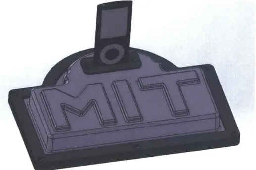
Figure 22: Assembled missing panel metal box design with integrated soldering iron holder
Figure 24: Close-up of the clear acrylic side-panel option
This missing side panel metal box design is shown in figures 22-24 with an integrated soldering iron holder and wool cleaning pot. This aspect of the investigation will be explained in detail in section 4.
Table 5: Bill of materials for the missing panel metal box design
Part Quantity Price Part Number Source
Missing panel metal box 1 37.60 563-CU712A Mouser
(15"x7")
.125" thickness acrylic sheet 1 11.46 44449 United States Plastic Corp. 4-40 V" machine screw 16 4.45 for 100 91772A1 10 McMaster
4-40 hex lock nut 16 4.07 for 100 9183 1A005 McMaster
3.3. Further Options
In order to cut custom holes into the boxes it is possible to CNC mill and drill the shapes. This would be possible but its drawbacks are the time required to setup the machine, difficulty in constraining the box and longer cleanup time among other problems.
As mentioned earlier, it is also possible to make fully laser-cut boxes with finger joints at each surface interface. The boxes could be attached with glue or screws interfacing with T-joints. This approach would require huge amounts of time and acrylic to create. However, it would mean total control over the
dimensions of the enclosures and the ability to customize all 6 sides of the rectangular box.
Different placements of the thermoform are also explored as shown in the SolidWorks outlines in figures 25-27. These variations allow for different sized projects to be integrated along with the speaker.
Figure 26: Fully acrylic lid design with thermoform moved to the center
4. CNC Wire Bender Project
The DiWire machine is a CNC wire bender that bends straight pieces of 1/8" and 1/16" steel, aluminum and brass wire into desired 2D shapes. It is a powerful tool that has the capacity to teach students about plastic deformation, structures, attachments, soldering and much more. This section of the investigation will explore the possibility of using the DiWire developed by Pensa Labs in educational settings. Specifically, a soldering iron holder was developed from the DiWire that students can bend themselves. This bend project was then integrated into the larger electrical engineering project boxes explored in earlier sections.
Figure 29: Close-up of the DiWire bend head and rollers for extending the rods
The DiWire can be used for an unlimited array of projects and can bend a great selection of shapes, so long as the bends are not too sharp or too short. The machine uses rotating gears to extend straight wire in front of the bend head and then deform a section to the desired angle. The angle is achieved by rotating the bend head so that it pushes against one side of the wire and bends it. Next the gears extend the wire to
the next bend point and repeat the process. In this way it bends the entire design in 2D. The DiWire software accepts .dxf and .svg files and converts them into a set of bend commands. If the bends are too sharp or too short it displays errors and various parameters can be adjusted to fix the errors. Some simple 3D structures can be created with the DiWire by rotating the wire as it is being bent. This can be achieved by introducing pauses to the bend commands. Ramps can also be used that rotate the wire gradually as it is extruded thus creating a gradual 3D curve to the wire (e.g. a spiral like the one shown in figure 30).
Figure 30: 3 views of a 3 inch diameter spiral bent on the DiWire as a preliminary test
4.1. DiWire Learning Objectives
Underpinning theory for students to learn:
" Plastic deformation of metals - similar to concepts taught in Advanced Mechanics of Materials
class (2.002) at MIT
* CNC wire bender mechanics and operation * Beam bending, shear and moment analysis
" Heating of the metal holder when the iron is placed in it - elements of heat transfer * Free body diagrams of supports of the soldering iron
4.1.1. Plastic Deformation of Metal Rods
The DiWire relies on the plastic deformation of metal wires to achieve the desired 2D shapes. The SolidWorks simulations below demonstrate the stress and displacement levels in an aluminum wire when bent. Figure 31 demonstrates the high levels of stress on the outside edges of the wire at the point where the bend occurs. Problem sets could easily be constructed that teach students about these deformations and the stress within the material. Figures 31 and 32 show simulations in SolidWorks which is a software package that all MIT students have access to.
Model name:Partl
Study name:SimulationXpress Study(-Default-) Plot type: Static nodal stress Stress
Deformation scale: 8.07393
4
y
Z41
von Mises (N/M A2) 1.631e+008 1.497e+008 1.362e+008 1.228e+008 1.094e+008 9.592e+007 8248e+007 6.904e+007 5.561e+007 4.217e+007 2.873e+007 1.529e+007 1.858e+006 -bYield strenath: 5.515e+007
Figure 31: Graphic of the von Mises stress in a 2" long, 1/8" diameter aluminum bar when deformed under 20N of force
Model name:Partl
Study name:SimulationXpress Study(-Default-) Plot type: Static displacement Displacement Deformation scale: 8.07393 Y URES (mm) ' .10e-001 2.896e-001 2.633e-001 2.?70e-001 1.843e-001 1 ,580e-001 1.317e-001 1.053e-001 7.899e-002 5.266e-002 2.633e-002 1,000e-030
Figure 32: Graphic of the displacement in a 2" long, 1/8" diameter aluminum bar when deformed under 20N of force
4.1.2. Metal Spring-Back and DiWire Calibration
Metals initially undergo reversible elastic deformation when forces are applied to them. At a certain level of stress, the metal enters a region of plastic deformation which is irreversible. If the metal is then unloaded, it undergoes "springback" where some of the strain is reversed. The DiWire must calibrate for this springback when producing bent parts. If the software did not account for springback the resulting part would be misshapen. Factors that affect springback characteristics are: type of metal, diameter of wire and wire manufacturing conditions. There is variety in the wires from batch to batch so the DiWire should ideally be calibrated for each new bundle of wire to ensure accuracy.
4.1.3.
Joinery
Figure 33: Photos from the DiWire website2 that show some clever use of laser-cut joinery
The laser-cutter is a great way to join wire pieces and form more complex geometries. I have had success with cutting .124" diameter holes into acrylic and achieving a snug fit when .125" wire is inserted into it.
Another option for joinery is soldering. This method can be used on any of the bendable wire types to produce rigid joints. The down-side of using soldering as a
joinery
method is the high-temperature torches which could pose safety risks.Pensa Labs also makes plastic clips that can join wires in parallel or perpendicular orientations. These clips can be attached and re-attached many times which makes them a versatile choice. However, they are not as heat resistant as a soldered joint which could be a problem when supporting a hot soldering iron. The cost is $20 for a pack of 100 parallel clips cut to 3/8". Pensa also offers 1 foot sections of parallel clips that can be cut to any size. These come in packs of 10.
Figure 34: Photos from the DiWire website that show plastic joinery produced by Pensa Labs
These attachments are also 3D printable. Pensa Labs provides the CAD. Figure 35 below shows the universal clips made by Pensa Labs. They can be adjusted to any angle and are heat resistant for soldering. They are $30 for a pack of 10 clips.
Figure 35: Photo from the DiWire website that shows the metal universal clips produced by Pensa Labs
4.1.4. DiWire Accessories
The DiWire has a hole on the side that is tapped with 6-32 threads. This hole makes for an easy
attachment point. I laser-cut an acrylic "ramp" that fastens to the side of the DiWire with a machine screw placed into the 6-32 tapped hole. This feature allows DiWire users to produce gradually bent 3D pieces (e.g. the spiral shown earlier). Laser-cutting the bend and figuring out the desired ramp angle would be a
great project for students to pursue as it would expand the possible uses of the DiWire and show how to make interesting 3D objects.
4.2. Prototyping the Soldering-Iron Holder
Professor Leeb acquired a small Weller soldering iron that would be a great tool for students. Having explored the functionality and possible joinery methods of the DiWire, I developed a project for students employing the machine and its relevant concepts. The goal is to create a simple holder based around the small Weller soldering iron. Many options are considered for the final design including laser-cut attachments, clip joinery, soldering, and continuous wire designs.
4.2.1. Acrylic Base Design
Figure 38: Close-up of the bent wires before insertion into the acrylic stand
Figure 39: 3 views of an alternate acrylic base design
The two prototypes with acrylic bases were successful and are stable holders for the soldering iron. The first design supports the iron in two places and is the simplest design. The one problem with it is that the tip of the iron is still exposed and could still cause harm if students are careless. The second design is better in terms of coverage of the hot tip and it can be made more stable by increasing the width of the
iron slipping out if placed incorrectly. The favored design is the first one because of its simplicity and
stability.
4.2.2. Continuous Wire Design
The simplest soldering-iron holder is achieved by using only the DiWire and bending one continuous piece of wire into a support structure for the soldering iron. The support is fairly stable and does not have the possibility of the wires popping out of the acrylic holes which is a drawback of the acrylic base design.
Figure 41: Alternate view of continuous wire design
This method requires the user to rotate the wire at various points in the bend process. This is made easier by adding "pause points" at specific bend points which is a useful feature of the DiWire user interface. It is still difficult to visualize which way to rotate the wire and it takes some time to master.
4.2.3. Clip Joinery Design
To reduce the complexity of the multiple rotations of wire and laser-cutting involved in the first two design approaches, a clip joinery design was explored. Pensa Labs provides plastic clips as shown in figures 42 and 43. However, the marginal benefits of using the clips does not outweigh the loss of stability from not having the holder be one continuous piece.
Figure 43: Close-up of clip joinery design
4.2.4. Interlocking Supports Design
Figure 44: Assembled view of interlocking supports design (left) and disassembled view (right) Note: Blue arrow indicates where soldering iron will be inserted
Figure 45: Interlocking supports design with adjustable metal clip attachment
The interlocking supports design consists of two wire bent sides that fit together and attach using a metal clip to provide a base for the cone-shaped section of the soldering iron. In theory the design would be very stable and stay in the orientation shown in figure 46 but in reality the iron often slipped as in figure 47 thus making this design unsafe.
Figure 47: Soldering iron slippage when placed in interlocking supports
4.2.5 Final Soldering Iron Holder Design Choice
The continuous wire design has many great features for a stand-alone soldering iron holder since
it only uses one machine and is very stable. However, since it turns out that this will be
interfacing with a fully acrylic lid, the best design choice is the acrylic base holder since the
wires can be directly inserted into holes laser-cut in the lid. A pot for steel wool can also be
added as a press-fit into the acrylic. The chosen 2 inch diameter pot is shown in figure 48.
Figure 48: Cleaning wool pot to be integrated into the soldering iron holder project Table 6: Bill of materials for the soldering iron holder design
Part Quantity Price Part Source
Number
1/8" rod 1
13.75
for bundle (30 - http://www.pensalabs.com/material/aluminumfeet)
2" diameter 1 15.75 for 12 4332T34 McMaster pot
4.3 Integrating the Soldering Iron Holder with the Project Boxes
Now that both the speaker enclosures and the soldering iron holder have been designed, they can
be combined to form a multi-faceted student fabrication project. Since the soldering iron holder
design is compact, it interfaces well with an intermediate sized enclosure that houses the
thermoformed speaker part with 3-4 extra inches on one side. This is shown in figure 49. The
holder also interfaces well with the largest enclosure size and leaves a few square inches for a
third element to the project to be incorporated.
-Figure 49: Soldering iron holder and wool pot integrated into the missing panel metal box design
5.
Conclusion and Further Work
This investigation has produced designs that are ready to be incorporated into MIT classes and start teaching students about novel mechanical fabrication techniques. The next step that will be taken is to design the speakers and electronics that will be incorporated into the enclosure and lid surface. One avenue to pursue is creating electronics that control the small Weller soldering iron and incorporating them into the enclosure. Desirable attributes would be a temperature read-out, dial for adjusting temperature and an on/off switch. Another aspect of the project to be sxplored is the connection of the setup to power sources. The current speaker design has a power cord connected through a hole on the side of the thermoformed part. The power cord attachment will need to be figured out for this new enclosure design. The list of other potential projects to include in the enclosure is endless and could make for many more exciting investigations.