AND SMALL COMMUNITIES
by
Mohammad Durali
B.Sc., Arya-Mehr University, Tehran
(1974)
SUBMITTED IN PARTIAL FULFILLM&NT OF THE REQUIREMENTS FOR THE
DEGREE OF MASTER OF SCIENCE
at the
MASSACHUSETTS INSTITUTE OF TECHNOLOGY MAY, 1976
Signature of Author...!
..
Z...
Department of Mechanical Egnineering, May 12, 1974
Certified 6...
Thesis Supervisor
Accepted by... Chairman, Department Committee on Graduate Students
JUL 9 1976
NhAftef6I-DES .GN OF SMALL WATER TURBINES FOR FARMS AND SMALL COMMUNITIES
by
Mohammad Durali
Submitted to the Department of Mechanical Engineering
on May 10, 1976 in partial fulfillment of the
require-ments for the Degree of Master of Science.
ABSTRACT
The purpose of this project was to study alternative water
turbines producing
5
Kw electric power from an available hydraulic
head of 10 m and sufficient amount of flow.
The work consisted of the preliminary design of different
types of water turbine which could be used for this application.
Then one was selected and designed completely.
Also working
drawings were drawn for the selected type.
Four different types of water turbine were studied: a
cross-flow (Banki); two types of axial-cross-flow turbines; and a radial-cross-flow
turbine.
Each one has some advantages and some disadvantages.
One of the axial-flow turbines (one with rotor blades having 50%
degree of reaction) seemed to be the best.
Thesis Supervisor: Title:
David Gordon Wilson
ACKNOWLEDGMENTS
I would like to express my appreciation to Professor David Gordon Wilson, my thesis supervisor who gave me a great deal of information and guidance during the course of this research work.
I also thank Ms. Leslie Buckley for typing this report. Financial support of the author during the period of research work has been provided by Aria Mehr University of Technology Tehran.
4
TABLE OF CONTENTS PAGE ABSTRACT 2 ACKNOWLEDGMENTS 3 TABLE OF CONTENTS 4 LIST OF SYMBOLS 6 LIST OF FIGURES 9 CHAPTER 1 - INTRODUCTION 11 1.1 Background 11 1.2 Problem Statement 111.3 Principles of Our Approach 12
CHAPTER 2 - DESIGN OF A CROSS-FLOW (BANKI) TURBINE 14
2.1 Description 14
2.2 Advantages of Banki Turbine 14
2.3 Analysis of the Machine 16
2.4 Design of the Rotor 19
2.5 Losses and Efficiencies 27
2.6 Blade Design 32
2.7 Sizing of a Cross Flow Turbine 41
2.8 Mechanical Design 45
2.9 Evaluation of Efficiencies 51
2.10 Radial-Inflow Partial-Admission Water Turbine 52
CHAPTER 3 - DESIGN OF AXIAL-FLOW TURBINES 55
3.1 Description 55
3.2 Advantages 55
3.3 Analysis 57
3.4 Design of Blades 59
3.5 Sizing of the Machines 62
CHAPTER 4 - DISCUSSION ON ADVANTAGES OF DIFFERENT TYPES 82
4.1 Improvements on Reaction Machine 84
4.2 Off-Design Performance 85
APPENDIX I - FRICTION LOSS IN NONCIRCULAR CONDUITS 138
APPENDIX II - EFFICIENCIES 140
APPENDIX III - PERFORMANCE ESTIMATION OF AXIAL-FLOW
TURBINES 143
6
LIST OF SYMBOLS
A area
B blade angle
b width of the blades C flow velocity, absolute c chord of the blade
d diameter
f friction factor
g acceleration due to gravity
H hydraulic head h blade height h enthalpy i incidence angle K head-loss factor L length
&
mass flow rateN rotational speed 0 opening of the blades
P pressure
Q
volume flow rater radius
s spacing of the blades
U
w
z
Wa
h
A
6
0
A
p
a
'V
SUBSCRIPTS
a
h
i
n
p
r
blade tangential velocity relative velocity, flow
number of blades
angle of absolute velocity angle of relative velocity drop or rise of a variable deviation angle
efficiency turning angle
stagger or setting angle mass density
solidity
flow coefficient work coefficient
speed of revolution (angular velocity)
annulus
hub
inlet leading edge mean value nozzle outlet profile8
t
tip
x
axial direction
*
stagnation property
1.
inlet to the blade
2
out of blade
LIST OF FIGURES
NUMBER TITLE PAGE
2-1 Cross-Flow (Banki) Water Turbine 15
2-2 Velocity Diagrams of Different Locations in 17 Cross-Flow Turbine
2-3 Effect of Blade Outlet Angle on Stalling 21
24 Velocity Diagram Terminology 23
2-5 Work Coefficient T vs. Relative Inlet Flow 26 Angle al
2-6 Converging Flow Inside the Rotor 30
2-7 Cross-Flow Turbine-Blade Terminology 33
2-8 Ratio of Blade Radius of Curvature R and 39 Rotor Length L over Rotor Outer Diameter
vs. Rotor Inner-to-Outer Dia. Ratio m.
2-9 Ratio of Radius to Hydraulic Diameter R/Dh, 39 and Deflection Angle of the Blade Passage
0 vs. Rotor Inner-to-Outer Dia. Ratio m.
c
2-10 Number of Blades Z vs. Inner-to-Outer Dia. 40 Ratio m.
2-11 Radial-Inflow Partial-Admission Water Turbine 53 3-1 Inlet and Outlet Velocity Diagrams of Axial- 56
Flow Turbine Stage
3-2 Blade Terminology 60
3-3 Impulse Velocity Diagram 63
3-4 Blade Sections of the Axial-Flow Impulse 69 Turbine
10
NUMBER TITLE PAGE
3-6 Blade Sections of the Axial-Flow Reaction 79 Turbine
4-1 Characteristic Curves of Reaction Machine 86 for Constant Flow Rate
4-2 Characteristic Curves of Reaction Machine 87 in Constant Speed
I-1 Loss Factor fur Bends. (ASCE, J. Hydraulic 139 Div., Nov. 65)
1-2 Friction Factor f vs. Re. for Different e/D. 139 (W.M. Rohsenow and H.Y. Choi, Heat, Mass and
Momentum Transfer, p. 58)
II-1 Scheme of Losses in Water Turbo-Generators 142 III-1 Turbine Blade and Velocity Triangle Notation 146
III-2 Lift Parameter, FL 146
111-3 Contraction Ratio for Average Profiles 147
111-4 Basic Profile Loss 147
III-5 Trailing Edge Thickness Losses 147
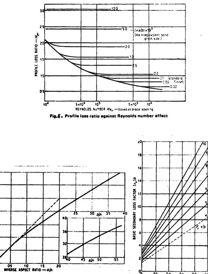
III-6 Profile Loss Ratio Against Reynolds Number 148 Effect
111-7 Secondary Loss-Aspect Ratio Factor 148
Chapter 1
INTRODUCTION
Not all consumers have easy access to electrical power
produced by main power plants. Sometimes it is not worthwhile for
small isolated customers to afford the transmission and maintenance
costs needed if they are to connect to the nearest main power.
Until the early 1970's an ideal way to produce small amounts of electrical power was to use diesel- or gas-engine-driven generators.
But with high energy prices, naturally available power sources as sun, wind, streams, small water falls and so forth can often be more economical, provided a simple and cheap device for each case can be made.
1.1 BACKGROUND
In the country of Colombia in South America most coffee farms are situated on streams where a head of 10 m can easily be trapped and there is sufficient flow available especially during the times when power is most needed. Although the price of mains electric power is not very high, the cost of transmission of power from the main power plant to the farms may be extremely high. Because of
this and also because the demand for electricity is seasonal, many farmers prefer tc produce their own electricity.
1.2 PROBLEM STATEMENT
12
5 kw electric power for the cases mentioned before. As this
machine would be used by farmers who on average have little
technical knowledge, one of the major objects is to avoid very complicated structures. Moreover the machine must not need skilled
maintenance. Finally the amortized capital cost for using this machine should be less than the total cost of using the transmitted
power produced by mains power plants.
Some members of the faculty of engineering of the Universidad de Los Andes in Bogota have worked on this problem. They have
developed a half-kw cross-flow turbine. They plan to modify that model for higher power levels. We have reported our work to this group regularly.
The design of small water-turbine units has not previously been carried to a high degree of sophistication. This might be because of their limited applications. For applications like the one we have (i.e. electricity needed in a period of year when there is plenty of water) the design of a cheap machine may be a good solution to energy problems.
1.3 PRINCIPLES OF OUR APPROACH
The effort was put into two different approaches to the problem.
a) Designing a machine which can easily be manufactured by any simple workshop having enough facilities to weld, drill and cut steel parts. Consequently, the machine can be built locally in
each farming area. The parts such as bearings, gears, chain, generator etc., can be shipped to each area. In this approach we tried to use materials like angle bars, sheet metal, round bars and so on which do not need much machinery to be used. Casting and other more complicated processes were excluded.
b) Designing a machine which could be manufactured and shipped to farming locations. This approach a kind of process layout is going to be arranged for manufacturing the machine. The production methods like casting and molding, and using plastic parts seems to be more economical.
In both cases a) and b), the design has to be within the area of the industrial capabilities of the country of the user. - The next chapter contains the design of a cross-flow tutbine based on the "a" assumptions. In the end of Chapter 2 design of a simple rapid inflow turbine is discussed very briefly. Chapter 3 is about
the design of 2 modified axial-flow turbines with short blades. The design of the two latter types is based on the assumptions made on
14
Chapter 2
DESIGN OF A CROSS-FLOW (BANKI) TURBINE
2.1 DESCRIPTION
This machine was first designed by Dr. Banki over 60 years ago. Since then some low-power models of this kind have been developed in Europe and have given good performances.
This machine is an atmospheric radial-flow impulse wheel which gets its energy from the kinetic energy of an inward jet of water. The wheel is simply a squirrel-cage-shaped assemblage of curved horizontal blades (Fig. 2-1) fixed between circular end plates to which the shaft is attached. The jet of water coming out of the nozzle passes through the rotor blades twice.
The blades have to be designed to direct the flow inward to the open internal space inside the cage and then to drain it to the tail water outward through another set of blades in another part of the inner circumference.
2.2 ADVANTAGES OF BANKI TURBINE
The cross-flow turbine has significant advantages which make it a suitable solution to our problem. Its simple structure makes it easy to be manufactured. The atmospheric rotor avoids the need for a complicated and well-sealed housing. The bearings have no contact with the flow, as they are out of the housing; they can simply be lubricated and they don't need to be sealed. And finally, when,
NOZZLE
ROTOR
TAILeWATER
2o
16
for a constant head and a given power level a simple fixed rotor
cross section is obtained, then for higher power levels one can
simply use a longer rotor.
2.3 ANALYSIS OF THE MACHINE
The most useful relation in design of a turbomachine is the
Euler equation,
UiCoi
-UoCeo
= gc(ho ,- h.0
)where U stands for rotor peripheral speed, C0 is the tangential component of absolute velocity of the fluid and h. is the stagna-tion enthalpy. Subscripts i and o stand for inlet and outlet of the rotor, respectively (Fig. 2-1).
The rotor normally is designed so that the absolute velocity of the fluid leaving the rotor is in the radial direction, so
Co
-O
and therefore
UC gc A h.
i-o
and then the parameter "work coefficient" for the rotor will simply
be
A(UC
0)
C
2
u E
FIG.2e2. VELOCITY DIAGRAMS OF DIFFERENT LOCATIONS IN
CROSSeFLOW TURBINE.
l8
From the first law of thernodynmitnlen,
-
A
h.
2- A he A (h + 2 + zg)
m
1-0 j-obut for water turbines the rate of heat transfer and change in static enthalpy are very small and for small units like the one we are to study the drop in height from inlet to outlet is negligible, so that,
--
Ah,
-y(C2
-C2)
using the equations we had before, U C
i
i
12 (Ci
(C -C)2C
2'v
21
2
2
''
2U2
(C- C
0)
or finally
U- (C -
C
2)
(aFor an impulse machine the value of T is normally taken equal to 2.0. If the total hydraulic head before the nozzle is AH, and riN be taken as nozzle efficiency (which covers the loss of kinetic energy through the nozzle) then equation (a) can be written as follows,
or C U.= 1 (AH, TN N -0)(2.1)2
From Eq. (2.1) we find that for a given hydraulic head, choice of the velocity diagrams enables us to determine the rotor
speed and hence rotor dimensions. 2.4 DESIGN OF THE ROTOR
The choice of the blade inlet and outlet angles is the important part of the design. They have to be chosen so that the jet of water transfers useful work to the rotor in both passes through the blades.
Throughout this analysis angles are measured from tangents to the circles and are positive in the direction of rotation. Also we assume that- at design point the incidence angle is zero and the
deviation angle is very small so that the design will not be affected if we assume the derivation to be zero. From Fig. (2-2) by simple geometry we have for all cases
a
2 =a3
This is true for all shaft speeds and flow inlet velocities. But one may question why the inter stage angle of the blades is taken equal to 90* (i.e. the outlet angle of the first "stage" or pass, and the inlet angle of the second stage). The reasoning behind this choice is as follows.
,d0(
Assume zero deviation angle for the flow leaving the blades
in the first pass; therefore, the flow relative velocity angle will be equal to the blade outlet angle. Now suppose that the angle of
the blade at the outlet of first pass is bigger than 90* (Fig. 2-3a). As you see there will be negative incidence at the second pass.
This time assume 82 < 900 (Fig. 2-3b). In this case positive incidence will take place. Now as a comparison in Fig. (2-3c) the situation is shown with
8
= 90.Therefore the optimum blade outlet angle has a value around
900. Now assume 6 as deviation angle at outlet of the first pass (Fig. 2-3d). If the blade angle is kept equal to 90* then there will be an angle of incidence "i" so that i = 6 (in the inlet of
the second pass). Consequently if the blade's outlet angle is slightly more than 900 (equal to 90 + 6/2) then the incidence will be near to zero.
Normally the values of deviation angle are of the order of 20 to 8. Therefore the optimum value for the blade outlet angle is between 91* to 94@* Obviously taking the blade angle equal to 90 would not cause much effect on the performance.
Because the cross-flow turbine rotor works totally at atmospheric pressure there is no static-pressure difference from inlet to outlet of a blade passage. Therefore the flow through a blade passage does not accelerate or diffuse. In fact, blade passages do not fill with water and flow passes through the blade passage as a jet deflecting
>5)
\7s
(a)
rn-rnNJ
(c)
\I
I
(b)
(d)d
along the pressure side of the bl.ade. Consequently the flow will have a constant relative velocity through the passage (in the absence
of friction) and the maximum flow will be determined by the smaller area of the passage which is at the inner diameter side of the rotor.
The rotor specifications are then as follows (Fig. 2-4): outlet relative velocity angle (first pass)
S
2 = 90* so from Fig. (2-4a) C 2 = U2 and the absolute velocity of water leavingthe rotor is in radial direction (Fig. 2-4b) a4 = 900. Let us define
- C61
(Notice that in this particular case x is equal to the work coefficient.)
and
r
r2 and r1 are inner and outer radii of the blading respectively,
therefore
U2 _U
3
1
4
The above definitions will help us to write simpler geometric
relations.
From Fig. (2-4a) we have
C0 1 C
cosal
-Cl cosa1
Ce'
Wei-Cr W(a)
C
6
3
us
UU2(Cb
(b)
24
Also,
Cr1 =C 1 sin 0 - cx) = W1 sin(t - Si) (2.3)
f rom (2.2) and (2. 3) tan X (tan
Qy
-tan a 1) Therefore = tan 1 ( X ) tan a) (2.4)From the outlet velocity triangle (Fig. 2-4a)
2
22
C2 = W2+ U
If we assume no loss of kinetic energy through the blade passage, then the relative velocity of the water has to remain unchanged along the blade passage, so using Eqs. (2.2) and (2.3) we have
2
C
2=1U1
(
si S
+ m
2 .(2.5)
But
C2 = - (2.6)
2 cos a2 Cos a2
Combining (2.6) and (2.5) we have,
a2 = os-1 M2 (2.7)
tan(x
From Fig. (2-4b) we have;
U
31
cos(-3)
= ---n=(2.8)
4 m W3 m tan a3
but as illustrated before at any condition x3 = a2 and if incidence and deviation angles are assumed to be zero then
SI
= 54 so from(2.8) we have:
tana
2 =mcos5
-1
1
a
2 = tan - s(2.9)2
M Cos8
Therefore we found two values for a2 , one by using the first "stage" geometry (Eq. (2.7)) and the other was found by using the second-stage conditions. Putting these two values equal we get a nondimensional relation between the design parameters m , x and a1 ,as follows:
tanl
1
= cos1m
2
(2.10)tan al 2 2 (-x sins) +n$
7
6
5
4
3
2
I
OL~Ar
0
T 9 w V V V U130
I
I
140
I I
'sir
160-I
- I I I I S I A I./00
'In
INr)
L30)
t40
gmo' %FU Uo %.W %or
3
1 m
FIG.2-5.
WORK COEFFICIENT*rVS. RELATIVE INLET FLOW
160
a
I
ABSOsLUTE INLET
FLOW
ANGLE-V,
170
180
ANGLES
.
170 9Notice that (1t , x and tiI are related together by Eq. (2.4).
Now design curves can be drawn using Eqs. (2.4) and (2.10) which may help to choose the right value of the parameters. Two useful curves may be,values of x vs. 8I for different values of nozzle angle
(a1), and values of x vs. 81 for different values of m . Figure 2-5 shows the design curves based on Eq. (2.4). Solving Eq. (2.10) for the value of X we get
1
2
x - m Cosa [ - 11] - 1 + 1 (2.11)
costaJ
'
m cos 81
For any value of m and 81 the value of x can be found, or vice versa.
2.5 LOSSES AND EFFICIENCIES
In cross-flow machines, blades are normally made of curved bent strips of thin sheet metal. So small variations in inlet flow angle could cause high incidence losses. Summarily the other losses can be listed as: hydraulic losses due to skin friction and change of flow direction in the nozzle and blade passages; losses due to converging flow in open space inside the rotor; and mechanical losses.
a) Nozzle losses
For nozzle a factor cv which acts as a velocity correction factor can be used to define the losses due to skin friction and converging flow, so
28
C
c = C1 v g2gAH0or
C
Cv\f2gAH
For the loss due to the curved nozzle passage the curve given in Appendix I, will be used, provided a hydraulic diameter is
defined as
D 4 x flow area (2.12)
h wetted perimeter
If the radius of curvature is R then the curve in Appendix I provides the values of loss factor k versus deflection angle
for different values of R/Dh , where
W2
H =
K-Loss 2g
and W is the mean water velocity through the nozzle. Obviously the mean values of R and Dh should be used to get a better result.
b) Blade losses
I) Hydraulic-friction losses. The coefficient of friction for the flow through blade passages can be found based on hydraulic diameter, and using the curve given in Appendix I. So
H f - X
--Loss h Dh 2g
subscript h stands for values evaluated on basis of hydraulic diameter. "L" is the length of the blade passage and W is the relative flow velocity.
II) Losses due to flow direction change. In this case we can use the curve given in Appendix I, as for the nozzle.
c) Losses within the rotor
As seen in Fig. 2-6, the direction of actual velocity leaving different blades converges to one point. This effect will cause a change in flow direction entering the second set of blades.
As seen in Fig. 2-6 from simple geometry, the maximum
incidence angle "y" caused by this effect is half of the admission angle "0". It is assumed that the central stream line remains
undeflected. Also the bigger the admission angle is, the closer the right-hand side jets will get to the inner surface of the rotor and that will cause negative work on the second pass. Therefore
the angle of admission has to be kept as small as possible. A reasonable range of magnitude for admission angle is between 20* to 400. For these values of admission angle the loss due to this effect
is very small.
d) Efficiencies
Normally the overall efficiency for a water turbine is
defined as;
30
p
E ihX
T T)n
n h mQ
where Th is the hydraulic efficiency of the turbine, and covers all the hydraulic losses across the blading. (See also Appendix
II).
AH - H
h -,loss
where AH stands for difference between hydraulic head of the turbine inlet and outlet.
The term n m or mechanical efficiency covers all the losses due to disk friction and bearings and so on and is defined as;
- T-Tloss
m T
where T represents the shaft torque.
Finally
n
is the volumetric efficiency which covers theleakages and the flow which passes the turbine without giving any power
Q - Qik
Q
Q
where
Q
is the volume flow rate.The important part of the evaluation of the efficiency of a turbine is to find the hydraulic efficiency. This term is very
32
sensitive to the blade profile and flow angles (see Appendix III). In order to get the hydraulic efficiency of the crossflow turbine
using Eq. (2.15), one has to write all the losses mentioned in the last section in terms of hydraulic head.
2.6 BLADE DESIGN
As mentioned before the rotor in a crossflow turbine
con-sists of two end plates to which the blades are joined. Many
designs do not have a through shaft, so that the torque is
trans-mitted to the output shaft by the blades, i.e. the blades experience all the bending moment due to torque transmission, all the blades
come under a relatively high periodic stress, as at each moment only a few blades carry the whole flow. Therefore one would like to avoid long rotor blades and blades with small radial chord.
Stiffer plates may be used to support the blades between the two end plates and so allow longer rotors. Therefore for a given power level and hence a specified volume flow rate, if the
rotor can be reinforced with stiffer plates one can go for smaller rotor diameter and longer rotors and hence higher shaft
speed. The cost for these apparent advantages is that of the higher complexity.
For the type of design we have chosen, we will only be concerned with rotors having no stiffer plates. Also the blade profiles will be segments of a circle. Therefore the blades can be cut out of thin-wall tubes, or made of strips of thin sheet
<0
Ze
number of blades
dim inner dia.
do! outer dia.
L ! length of rotor
34
metal rolled around a pipe. The most important parameter to be
specified is the ratio of inner to outer diameter of the rotor
"m" which affects most of the other rotor parameters, such as
length, number of blades, etc., effect of m on other blade
design parameters can be found using Eqs. (2.13a) to (2.13f) which relate these parameters. (See Fig. 2-7 for blade notation.)
0
Y - = 0 (2.13a) 2y -4) = B- (2.13b)2
d c sin y 2 - sin4) (2.13c) R= s c/(2.13d)2 5if(O
C/2)
d - d
c cos y + d sin $/2 = 02(.02
(2.1l3e)
a
= d sin u/Z (2.13f)The solidity a is defined as the ratio of the blade chord to the spacing of the blades on the inner-diameter side of the rotor.
It will be easier to work with the nondimensional forms of Eqs. (2.13a) to (2.13f). Let's define
A 2 and
R
w
0 0 then,y
=6c/2
(2.14a) 2y- B-
(2.14b) 2Asiny sin$ (2.14c) = 2 sin yA(2.14d)
cosy + sin /2 = (1-M) (2.14e)
A2
a
=m sin
Tr/Z .(2.14f)
As discussed in the last section the hydraulic loss through the blade passage is a function of the ratio of the radius of curvature of the blade camberline (centerline) over the hydraulic diameter of the passage and the deflection angle of the blade. Figure 2-8 shows the variation of the ratio of the rotor length and the blade curvature ratios over the rotor outer diameter versus values of rotor inner-to-outer diameter ratio. These curves show
that shorter and more curved blades result from using bigger values of m.
36
As ment joned in Sect LIon 2. 5 the
loss
th rough tithe bI adepassage is a funct ion of 1he ratio R/D1 and () , where 1) IS
the passage hydraulic diameter and 0c is the blade deflection angle. Bigger values of R/Dh and smaller values of 0C give us less loss. Both these parameters can be found in terms of geometrical parameters introduced in Eqs. (2.13) and (2.14), as follows:
as definedDhS 4 x flow
s dwetted perimeter
but as pointed out before, flow through the blade passage is the deflection of a jet of water along pressure side of the blade and so the jet thickness is fairly constant. Consequently the hydraulic
diameter of the blade passage can be determined by the inner-diameter side of the rotor. By the aid of Fig. 2-7 we then have
D -4 x (Lxs)
h L + 2s
The reason for defining the wetted perimeter as (L +2s)
is that the flow does not fill the passage fully. Only the blade's pressure side and side walls guide the flow. If W1 is the
relative velocity of water through the passage and a is the rotor admission angle then at the inner-diameter side of the rotor we have:
but as m=..d /d ,then
L
--11W
m d
360 i W1 m
o
Defining a E c/s and A = c/d (Eq. (2.14) therefore,
d XAd
S c=c=. 3
0
Substituting these into the relation for Dh we have: ddA
u
mW da
D
360
1 o
Dh = A
360
m W1dDividing both the denominator and the numerator by d and naming
C'
E IT d W thea we haveC'
A
4- x-d m a 0 h C' Am
a
38
Also from Eqs. (2.14) we have the definition of
R 0 or R = Cd Therefore C' 2X R
-+-R_
_m
a
Dh 4- xm
a
or R_ _ (C'a + 2Am) Dh 4C' AThe parameter c' will be a constant value for homologous units of this kind (turbines having similarity in geometry and velocity diagrams). Figure 2-9 shows the variation of 6C versus m and the variation of R/Dh versus m for different values of
solidity. From Fig. 2-9 we find that the maximum value of R/Dh happens at values of m closer to unity as solidity increases. With reference to Fig. I-1 (Appendix I) we find that the loss
factor for the range of deflection angle we have (between 41* to 58*) does not change much with variations of 0C but is strongly a function of R/Dh , especially for lower values of R/Dh (values
from 1 to about 5). Consequently for a chosen value of solidity a, the maximum value of R/Dh seems to lead to the efficient passage.
.8
.6
.4
.2
.7
N --L.8
.9
I.
U,0
ANGLE
OFDMISSION
NOZZ&,ANGLE
.8
-. 6
FIG.2-8. RATIO OF BLADE RADIUS OF URVATURE RAND ROTOR LENGTH
L
OVER ROTOR OUTER DIAMETER VS. ROTOR INNEReTO-OUTER DIA. RATIO m
So
'.5
U
E
'
N
Iliillll
IUNE
MAXIMUM
.5
'?68
.6
ANGLE OF ADMISSION
300
NOZZLE ANGLE
30
.- II.7
m
.9
i.
80
60
40
20
0
P19.2-9. RATIO OF RADIUS TO HYDRAULIC DIAMETER
R/g
,
AND DEFLECTION
ANGLE OF THE BLADE PASSAGE
VS. ROTOR INNER-TO-OUTER DIA. RATIO m.
b'
yM'l
.6
8
6
4
2
0
LJ
0.5
. fI ok sc
60
ACCEPTABLE
REGION
000000*
1 40 IIIIIIIIIIIIIIIIIIIIIlljlllllllllllliiiiiil1111,11,1111111111111111,1111111111IIIIIIIIIIIIIIIIIIIIIIlljliiilllllllllllllllllo o oloo7000FLINE OF
109
X
o7
08 160 z mFIG.2-10. NUMBER OF BLADES Z VS* INNER-TO-OUTER
DIA. RATIO M
T
on
MIAIMUM LOSS
I IROTOR ANGLE OF
a
ALMISSION 30
I I Arr U- a AF AF, I -r-i jm Fl ir -y- 0 I I40
20
I I I I qr -LI -- dop-- -. dop- m I I I I I120 1
The design of the rotors with no stiffer plates is more dominated by mechanical design of the blades than by optimization to get the mini-mum loss. Using Eqs. (2.14a) to (2-14f), the curves shown in Fig.
2-10 can be drawn.
These curves show the number of blades for each choice of solidity and rotor inner to outer diameter ratio. As the number of blades is reduced the rotor becomes longer because the throat width is lessened (Fig. 2-8). Therefore although the blade chord
increases as the number of blades decreases the blades become more flexible in bending. On the basis of stress and stiffness
conclusion, assuming typical material properties and thickness (e.g. 2mm steel plate for the blades), we have let 18 as the minimum number of blades.
When the number of blades is increased, the rotor can be shorter, but the manufacturing difficulties for small workshops become progressively more severe. We have chosen 60 as the
maximum desirable number of blades. Points inside the closed curve drawn in Fig. 2-10, give better designs as far as losses and structural stiffness are concerned.
2.7 SIZING OF A CROSS FLOW TURBINE
For a machine of this type working under constant head, the velocity of jet of water leaving the nozzle is fixed (Section 2.4). Therefore the choice of inlet absolute flow angle from the nozzle affects the size of the rotor, a small nozzle angle being desirable.
42
As discussed in Section 2.5, the angle of admission should also be kept small in order to reduce the losses within the rotor and
losses due to flow entering the blades in the second pass. The angle of admission is taken equal to 30 in our machine. The inlet absolute flow angle in a prototype designed by Banki was 160. In
that design the flow crosses the rotor on an approximately horizontal line (i.e. the water entrance and draining points are on a horizontal line). He used a cast casing incorporating the nozzle for his
turbine.
As we have tried to avoid complex structures and manufacturing processes, our design does not have a cast casing like Banki's
design had. Rather we used a steel angle framework with sheet metal covers; there will be a main cover around the rotor which
confines the water spray. The nozzle will be a separate part fixed to the frame giving a nozzle angle of 30. That value resulted in the least complexity of the structural design. (See nozzle rotor combination drawing in Section 2.8.) So with reference to Section 2.4 the absolute inlet flow angle "Ila1 will be 1500. Draining will be vertically downward.
From the fact that the work coefficient is equal to 2.0 we have
C = 2U.
Assuming a total-to-total efficiency of 75% for the turbine (nozzle and rotor), from Eq. (2.1) we get,
A(c
0)
- 69.20 m/S2then
U1 = 5.88 m/s C = 13.88 m/s
W 1= 9.00 M/s
The choice of shaft speed depends on how large the rotor
outer diameter can be and what are the speed limitations for the
bearings. As we were to use wooden bearings the sliding velocity between shaft and bearing bore limited us to a shaft speed of
300 rpm. This speed is lower than desirable, because a high gear up ratio is needed to reach the shaft speed to 1800 rpm
(generator speed). In future design studies it would be justifiable to specify bearings to run at high speeds.
Therefore specifying N = 300 rpm we get
d
= 0.3743m.0
We would like to join the blades to the side plates by rivets (see general arrangement drawing and nozzle-rotor combination
drawing in Section 2.8). Therefore we would like to have the least possible number of blades in order to get sufficient space for riveting the bent ends of the blades to the side plates. Using Fig. 2-10 in the last section we get m = 0.6 and 24 blades.
43
Now using Kqs. (2-13a) to (2-13f) we get the following results and blade parameters. First from the velocity diagram (zero incidence) we get
B
= 1300 53' and then 6 = 520581 c Y = 260 29' R = 0.0956 m S = 0.0293 m C = 0.0843 m we have previously chosen,Z = 24
M = 0.6
The inner diameter of the rotor then will be
d
=
0.2246
m .
If 20% extra power is specified to cover the mechanical losses and the losses in the generator then the output shaft power has to be 6 Kw. The volume flow rate required will be
Q
=4(UWC6)
= 0.0867 m3/S
L
. =-W d
1W
10.164 n
a being the admission angle.
Once more recalling the velocity triangles shown in Fig. 2-4, we can write the following relation
A(U CO)total
= A(UC
0)
st passA (U C
)2nd pass
A(U
C0 ) =(UC
-
U
2%2) +
(U
3c6 - U
4c
0)
but as we specified, U2 -U3 C 2U1
U
1i
,Cg
= 0
a
04
C =C =Und
A(U C)
total
2 =2U
1 ThereforeA(U
c6)1st
pass
= -2
1
2
2 2U2 =2U1-mU
1, 2 2U2(l
-2
and
A(U
C
0)2nd
pass
2
m2U2=
U
mU
or
45
The above retttons show that for a value of in 0.6 , the energy
transferred to the rotor in first pass is 82% of the total energy
and only 18% of the total energy is received by the second pass. This means that as hydraulic losses within the rotor and the
entrance losses in the second pass do not affect the performance of
the turbine very much.
2.8 MECHANICAL DESIGN
The manufacturing processes under which the turbine is to be made have been the most dominant parameters in the mechanical
design. The general arrangement drawing, scheme of the nozzle
rotor combination and an isometric view of the machine are submitted in the following pages. Different parts of the machine are briefly described as follows:
Rotor
The turbine has a squirrel-cage-shaped rotor, 380 mm O.D. and 165 mm long. The optimum speed under the design head of 10 m is 300 rev/min.
It has 24 blades, each blade being simply a circular segment. Blades can be rolled out of 2 mm galvanized steel sheet (see Part 11 on the general arrangement drawing). They are joined to the rotor side plates with rivets (Part 12).
The rotor has no drive shaft. Power is transmitted through the bearing housing which rotates with the rotor, and the shaft which goes through the rotor bearing supports only the rotor
35
1~
'9H-IT
1-12I'-I
I
32 31 34 32GENERAL ARAAGEMENT DRAWING OF CROSS FLOW MACHINE
35 12 15 14
z
3147
IAI
K?
am=
...r
NOZZLE-ROTOR
COMBINATION OF
CROSS-FLOW
TURBINE
7/
0 xooov /
49
Bearings
The bearing housing, which is a short piece of circular steel pipe, is welded to a circular plate which is fixed to the rotor side plates with rivets (Part 13).
Bearings are made of a special oil-impregnated wood. Although there are some limitations for the maximum permissible speed for this kind of bearing, its low cost and simplicity makes it suitable for low-speed applications. Furthermore it does not need lubrication. It works in wet as well as in dry conditions. It requires no seal
(Part 15).
In our design the bearing rotates with the rotor, so equalizing wear on the wooden bearing and increasing the bearing life.
Chain transmission
Power is transmitted from the rotor to the generator by means of bicycle chain and gears. A 52-tooth gear is fixed to the circular plate which is welded to the bearing housing (Part 21).
The generator has a constant speed of 1800 rev/min. A chain and gear combination is used which gives a speed ratio of about six
from turbine to generator.
A complete hub and set of five chain cogs for a bicycle derailleur gear is used for the second speed step up (Part 22).
The unnecessary gears in the gear set are replaced by spacers and only an 18-tooth gear (being driven by a 52-tooth gear on the rotor) and a circular plate with a central bore, the same as one cf the gears, is fixed to the gear set. The latter circular p-ate is
be fixed with a 36-tooth gear being used for the second speed-up step (Part 23). The last gear has 17-teeth and must be fixed to the generator shaft. For the power level we have in this machine a good lubrication condition should be provided for the chain.
The two-step transmission in this turbine makes it difficult
to incorporate an oil bath around the chain. As you will see in Chapter 4 this machine would not be selected as the final choice, so we did not do further improvements on its transmission system.
In order to increase the life of the chain and sprockets, we recommend
that two chains in parallel be used. Therefore two sprockets should be installed side by side on each shaft.
Housing
The housing is completely made of thin galvanized sheet steel. It has a fixed section which covers most of the rotor (Part 31), and a removable door (Part 32), placed in the back of the turbine, for
servicing. It has a lifting handle and is fastened to the fixed section with two simple latches (Parts 34 and 35).
Frame
The frame is totally made of angles, welded together. The generator mounting is a steel plate welded to short legs and its size may vary when using different generators (Part 38).
Nozzle
The nozzle is completely made of steel plates, welded together (Part 41). The flow can be changed and set on different valves for different output powers. This is possible by chaning the angle of
51
flap (Part 42). The semi-circular channel (Part 43) which is welded to the flap has holes for different settings.
Warning: never change the flow while the turbine is in operation
As the system works under a relatively high head, a change of flow while the turbine is working can cause "water-hammer" in the piping which can result in serious damage.
To avoid this there has, to be a gate valve before the nozzle. The flow must be slowly reduced almost to the shut-off position before changing the flap position. After setting, the valve must be opened gently.
The possibility of installing a surge-tank as a shock absorber has not been studied, because it would increase the size and the cost of the turbine.
2.9 EVALUATION OF EFFICIENCIES
Knowing the size of different parts of the turbine the hydraulic efficiency of the turbine can be found. Following the method given in the last sections we get:
-h
= 76%
This efficiency is the total-to-total efficiency and is very close to our prediction, so the design is acceptable. Taking the effect of the energy loss by drain flow into account we get,
-If a mechanical efficiency of 94% and a generator efficiency of 90% is assumed then
Tit-sm =
56.5%
andn
t-su= 51%(See Appendix II.)
2.10 RADIAL-INFLOW PARTIAL-ADMISSION WATER TURBINE Description
This type of turbine is a potential alternative to the cross-flow and axial types.
The turbine simply consists of a spiral-shaped distributor with rectangular cross section which distributes the flow in two
opposite portions of its inner circumference, each one being an arc of 800. The rotor blades are rolled out of sheet metal and are fastened at one end onlyaround the circumference of the turbine disk as cantilevers. The flow enters the rotor with a swirling radially inward motion, passes through the blades while still in the radial plane, and subsequently is deflected to leave the rotor in the axial direction.
Flow Control
This type as described gives the possibility of controlling the volume flow to the rotor under constant head. Therefore the velocity diagrams would keep their design-point geometry and
consequently the tarbine would work at its design-point efficiency
through the whole range of power.
ROTATABLE SLEEVE
SPIRAL
NOZZLE BLADES
53 a. a I-/
I
FIG.2-11. RADIAL-INFLOW PARTIAL-ADMISSION WATER TURBINE.
BODY
BLADES
4-UF
IROTOR
ROTOR
The control of the flow could be easily achLeved by reducing the angle of admission. This could be done by installing a rotatable sleeve between rotor and distributor. The sleeve would have ports which could be brought more or less into alignment with ports on a
fixed sleeve to vary the admission area. Dimensions
For specified head (10 m) and power output (5.5 kw) a turbine of this type would have a diameter of about 220 mm when turning at 450 rpm. However, with this size of the rotor there would be drain-ing problems on the inner side of the rotor.
Unfortunately, increasing the rotor diameter brings out another problem which is the spiral geometry and size (see Fig. 2). To solve the draining problem by increasing the diameter to 340 mm would reduce the axial width of the rotor to 55 mm and the speed to 300 rev/min.
This would require a spiral distributor of the same width (55 mm). To keep the fluid velocity in the spiral small, the radial dimension of the spiral would have to be increased.
Conclusions
A rectangular cross section of the order of 60 x 200 mm would result (in entry port). For the range of specific speed in which we are working, dimensions as large as this make the radial inflow
55
Chapter 3
DESIGN OF AXIAL-FLOW TURBINES
3.1 DESCRIPTION
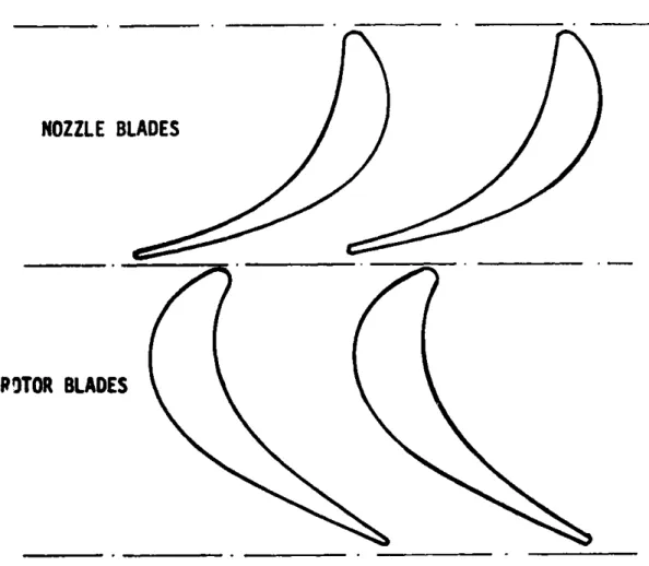
In this chapter the task is to design some simple axial-flow turbines as a solution to the problem. We have chosen to design machines with high hub-to-tip-diameter ratio which enables us to use untwisted blades for the blading.
Principally, water flows through a set of nozzle blades (installed all around the circumference of the hub disk), into the rotor blades, then passes the rotor blades and through the diffuser
to the tailwater. The turbine can be designed as an impulse or a
reaction machine.
3*2 ADVANTAGES
These designs should have comparable advantages with the Banki type. The design of these machines provides easy manufacturing
processes if they are to be mass produced (i.e. sand casting and plastic moldinb).
The blades are made of molded, extruded or cast plastic which will give accurate profiles and consequently a better design
and off-design performance. Moreover the shaft speed in these machines is higher than that of the Banki type and therefore a
simpler transmission and a lower gear-up ratio will be needed. These machines can also be used as a drive motor to drive other machines
besides the generator.
NOZZLE
BLADE
ROTOR
BLADE
L,
4-
2FIG.3-l. INLET
AND OUTLET VELOCITY DIAGRAMS OFAXIWL-FLOW TURBINE STAGE.
3,
C 1
57
3.3 ANALYSIS
Similar to the analysis shown for the cross-flow turbine, we
can write Euler's equation to relate different velocity-triangle specifications together (Fig. 3-1).
h01 -h02 1
C61- U
2C
0 2 . (3.1)But if AH0 is the total hydraulic head difference across the rotor then
h01 - h02 ttAH g (3.2)
where ntt is the total-to-total efficiency of the turbine (see
Appendix II).
The three parameters: flow coefficient, work coefficient and reaction which specify the type of the velocity diagram and
blading are defined respectively as follows:
C
S- - (3.3a) U1Ce -U
2C
02 2 (3.3b) C20( + C362 R S 1- 2U (3.3c)The analysis is done for the mean diameterfor the usual case where C retains constant from inlet to the nozzles to outlet of the rotor. Now for each design a velocity triangle can be chosen, hence values of
4,
$ and R can be specified.A good approach to the design of different machines of this type with different degrees of reaction is to keep the inlet flow angle to the rotor "a " constant and to vary the two other parameters
(i.e. R and $).
From (3.2) and (3.3b) we have
Us= t g .0(3.4)
Now, choice of shaft speed gives us the mean diameter
d
60 U
(3.5a)m
W (RPM)
and
d - dt + dh (3.5b)
M 2
and mass flow rate will be
W (3.6)
A(U
C)
59
The annulus area then will be
A
&
-mp
(3.7)
where p is the density.
Also we know that in terms of hub and tip
diameters the annulus area will be
Aa
=(d~
-dh)
(3.8)
As mentioned before we try to keep the ratio of hub to tip diameter high enough, to be able to use untwisted blades. A reasonable value for this ratio is around 0.8.
Now, a choice of velocity triangle gives us the value of A(U C0) and hence from Eq. (3.4), (3.6) and (3.7) the values of UAa are found. Then the shaft speed can be determined and using
Eq. (3.5a) gives us the value of mean diameter. Then using Eqs.
(3.5b) and
(3.8)
we can find dh
and
dt *
If the ratio of dh/dt is not acceptable a new shaft speed has to be chosen to optimize the dh/dt ratio.
3.4 DESIGN OF BLADES
Figure 3-2 shows the terminology used in this design procedure. To find blade angles from flow angles we may use the
inform tion and curves given in Reference (2). The following two relations approximate the curves given in Ref. (2) with a good
BLADE WIDTH
b
LEADING EDGE
--'4FLOW
INLET
ANGLE
atu Anr nar
IA C
LA
ILAUE
IULEIANGLE
INDUCED
INCIDENCE
ANGLE
A-STAGGER
ANGLE
\TRAILFLOW OUTLET
ANGLE
BLADE
ANGLE
OUTLET
82
"DEVIATION ANGLE6
ING EDGE
FIG.3-2. BLADE TERMINOLOGY.
61
accuracy, for incidence and deviation angles.
A
ind =0.25(-70
- 1)(2.6 -a)
a
1a
1-0.08
+
(
60-A2
c/s3
6
(3.9)
(3.10)
Please see Fig. 3-2 for information on parameters used in above
formulae.
These two formulae are useful in preliminary design.
In Eq. (3.10), 0c or blade turning angle is equal to
O
c a81
+Aind +
0a2+
6
so the blade angles will be
B1
81 + A
indB
2 -82+6
Suggested values for leading and trailing edge radii are
r
e
-(0.03 to 0.05)C
-
(0.02 to 0.01)C
and
The design procedure for the blades is to choose a stagger angle "A" and an optimum value for solidity a . The optimum
solidity can be estmated by the Zweiffel criterion for the value of
width-to-chord ratio;
b a 2.5 cos
2a(tgi + tgc
2)
(3.11)
also from Fig. 3-2,
b Wcos A (3.12)
c
from Eqs. (3.12) and (3.11) we find a
,In steam and gas turbines the dimensions of the blades and the number of the blades are normally determined by choosing a reasonable value for chord as far as vibration and stresses are concerned. In our case, as blades are short, a good choice for the number of the blades which gives us a reasonable blade passage seems
to be a good approach.
Then finding the dimensions of the blades we can find the
blade shapes by trying different curves for the blade profile.
3.5 SIZING OF THE MACHINES
63
basis of their velocity triangles. Two possible and most common types of velocity triangle are: impulse and 50%-renction.
The design procedure in each case is to guess a value of total-to-total efficiency for the turbine. Then the machine will be designed with respect to the estimated efficiency. Finally for the designed machine the efficiency will be calculated using the method given in Appendix III. The design can then be optimized.
In order to get 5Kw. electrical power from the generator the turbine itself will be designed for 10% extra power. So the specifications of the turbine are 5.5 Kw. output power and 10 m.
hydraulic head.
a)
Depjgof
an
impulse machine
Assumptions are a total-to-total efficiency of 0.80 and velocity-diagram specifications of: work coefficient of 20
(implicit in an impulse machine), and flow coefficient of 0.8 (which gives an acceptable nozzle angle). Also we will specify that the absolute velocity leaving the rotor is to be in the axial
direction, to minimize leaving losses therefore we have,
2
C 2
AR0 - H0 1 - 0 - 2
from Fig. 3-3 we have,
C C
U
Substituting the last two relations into Eqn. (3.4) and rearranging
for
U
we have:
n gHl
U 2
2
applying numerical values we have (at mean diameter);
U
-5.90 m/S
so
m $U2 =
69.75 m2/s
2
Then from Eq. (3.6) the volume-flow rate is
Q
=
0.0791 m
3/s
Then from the velocity diagram
a
1{
802
-68.20
-0
-5l.34*
-51.34*
and
A (UC e)65
and
C
1 =13.26
m/s
W
saW2
-=7.38
m/s
C
2 -3.54
m/s
The choice of the shaft speed has to be done with regard to the
following considerations: a) the value of hub-to-tip diameter ratio
should be around 0.8; and b) a combination of two standard available
sprockets can be found which gives us 1800 rev/min on the generator
shaft. The minimum number of teeth for a 1/2"-pitch sprocket
spinning at 1800 rev/min is 24 teeth.
This value is recommended
by almost all manufacturers.
Therefore the value of shaft speed
gotten by specifying the hub-to-tip diameter ratio should lead to
an available number for sprocket teeth.
With regard to the above discussion a shaft speed of 540
rev/min gives 80 teeth for the big sprocket. The dimensions of the
rotor then will be
d
-0.2087 m
U
and
dt = 0.2347 m
dh = 0.1827 m
blade height = 0.0260 m
The ratio of hub-to-tip diameter ratio is then 0.78 which is in an acceptable range.
Blade design. Nozzle and rotor blades should be designed separately for this machine as they have different flow inlet and outlet angles.
First for nozzle blades: by looking through curves and information given in Ref. (2) for different blade profiles, for cases having the same deflection and inlet angle, an optimum solidity of 1.5 and a stagger angle of 45* are suggested. (We tried several profiles with other staggers but this value gave the best-looking profile.)
From Eqs. (3.9) and (3.10) we have:
AGind - 19.250
6 - 5.09*
The blade angles are then
B:
:19.25*
67
To spacing.
choose the number of the blades we have to specify the From the above specifications we have
b _ cos
45 - 0.71c
- 1.5
s
(See Fig. 3-2).)
In this case a different number of blades
15 blades seemed to be a good number as it gives
sectional area for the blades (as we want to use
prefer to have blades with bigger chordal length
cross-sectional area).
With the above specification nozzle blade
follows:
sm
C
b
r t
were tried. Finally
a reasonable
cross-plastic blades, we
and hence more
sizes are as
=0.0434
m
=0.0651 m
-0.0462 m
-0.0025 m
-0.0005 m
In the same way calculations for the rotor blades were
done. The results are tabulated in Table 3-1.
Also see Fig. 3-4
for blade sections.
NOZZLE
0.0
68.2
15 1.5
45
19.25 5.09 19.25 73.29 43.4 65.1 46.2
2.5
0.5
12.4
BLADES
ROTOR 513 51.3 16 1.5 30 5.13 6.27 56.34 57.57 40.7 61.6 53.35 2.5 0.5 21.8 BLADES