DESIGN OF A REAR POWERTRAIN AND SUSPENSION SYSTEM FOR AN ELECTRIC VEHICLE
By
Jacob Charles Fisher Submitted to the
Department of Mechanical Engineering
In Partial Fulfillment of the Requirements for the Degree of Bachelor of Science in Mechanical Engineering
at the
Massachusetts Institute of Technology
February 2018
2018 Massachusetts Institute of Technology. All rights reserved.
Signature of Author:
Signature
redacted
Signature redacted
Jacob Fisher January 26, 2018 Certified by:
Daniel Frey Professor of Mechanical Engineering
Signature redacted
Accepted by: MASSACHUSETTS INSTITUTE OF TECHNOLOGYLIBRARIES
Thesis Supervisor Rohit Karnik Associate Professor of Mechanical Engineering Undergraduate OfficerDESIGN OF A REAR POWERTRAIN AND SUSPENSION SYSTEM FOR AN ELECTRIC VEHICLE
By
Jacob Charles Fisher
Submitted to the Department of Mechanical Engineering On January 26, 2018 in Partial Fulfillment of the Requirements for the Degree of Bachelor of Science in
Mechanical Engineering ABSTRACT
This is the summary of the design process of the drivetrain and suspension systems made for the purpose of converting a 1972 Opel GT to electric power. The goals of this study were to optimize the suspension for ride handling as well as integrate the suspension and power systems into a single modular unit that could then be tweaked for integration into other electric vehicle conversion projects.
Thesis Supervisor: Daniel Frey
TABLE OF CONTENTS
1. Introduction ... 7
2. Vehicle Param eters and Design Goals ... 8
3. Suspension Design ... 12
4. Subfram e Design ... 15
5. Acknow ledgm ents ... 17
1. Introduction
Electric vehicles are becoming ever more popular as gasoline prices increase, electric vehicle performance gets better, and their driving range gets longer. With the popularity and success of Elon Musk's Tesla, we see more and more traditional automobile companies catching on to the trend of electric vehicle. However, before these recent successes, electric vehicles were largely obscure and few in number, many of which were built from scratch or converted from existing gas powered vehicles.
Electric vehicles are quite popular on the MIT campus, however usually in a much smaller form, usually scooters, bicycles, or skateboards ridden by students in order to speed up long walks between dormitories and classes. My own interest in electric vehicles started
by wanting to make a small electric vehicle such as these. With this interest, I joined the
Electric Vehicle Team.
The Electric Vehicle Team, or EVT for short, however, does more than make small electric vehicles. The team started from a student's design project very similar to this one focused on converting a 1976 Porsche 914 to electric power, before being worked on by a team over the summer months. That vehicle is now often used for recruiting new members for the team and helping the team's mission to research electric vehicles and educate people about the technology.
Since then, there have been several projects, such as converting a racing motorcycle to electric to race in the now-annual Isle of Man TT zero, a variant of the famous annual motorcycle race but focused on zero-emission motorcycles, the pace of which is quickly catching up to its gasoline counterpart. Other projects have been converting a hybrid car into
a fast-charging electric vehicle, and building a long-range electric tricycle capable of traveling
180 miles in a single charge.
In terms of converting electric vehicles, older "antique" vehicles tend to be easier to convert because they lack many of the complex systems the modern gasoline vehicles use, meaning that the systems required for an electric vehicle can be installed on top of the minimal systems left when stripping out the gasoline components of the vehicle. This design study focuses on a one such vehicle, a 1972 Opel GT
2. Vehicle Parameters and Design Goals
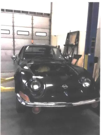
The 1972 Opel GT (as pictured in Figure 1) used for this study is a front-engined, rear-wheel drive car. The original vehicle had an approximate curb weight of 970 kg (2138 lb), 52% of which was distributed on the front wheels, and 48% on the rear wheels. The vehicle has an independent double-wishbone front suspension with leaf springs. The rear had a non-independent live axle suspension, with a Panhard rod and coil springs between the axle and the chassis, with drum brakes for the rear. Table 1 summarizes the parameters of the original vehicle.
For the electric conversion, the engine, and gas tank, as they were unnecessary for the electric drivetrain. We had chosen a Siemens 1PV5135 induction motor for the motor, as it was a rather common motor available for purchase from EV automobile part stores, which was capable of outputting 100kW of power. It was quickly determined that simply connecting the motor to the existing transmission would lead to a very high chance of destroying it as the original engine of the Opel GT had a maximum power output significantly less than that of the motor.
The reasoning behind using a significantly more powerful motor was that the ultimate goal of the converted vehicle was to have a car that could outperform the original, and match the performance of more modern cars. Using MATLAB simulations, we had estimated that the finished vehicle could reach a top speed of approximately 90 miles per hour, and have a
0-60 acceleration time on the order of 5 seconds, and at full acceleration, cover the distance
Siemens/1 PV5135 4WS1 4-215V/400A
Steady-state speed:92 mph -Energy Consumption-22.87 kWh/1 00 mile
Motor Force & Drag Force @ Wheel Motor Power and Resistance Power
___ ___ __ 200
Drag Force - Motor Power
6000 Motor Fo-ce 150 - Drag Power
4000 50-2000- so-5 0 20 40 60 80 100 120 Speed [mph] 140 0 Acceleration Profile 20 40 60 80 100 Speed [mph] 120 140 5 10 15
Range at Constant Speed (w174.3 kWh peck)
0 20 40 60 Speed [mph] 80 100 20 Time [sec] 60 E 0 0 40 L[2o 25 30 35
Energy Consumption at Constant Speed
20 40 60
Speed [mph]
80 100
Figure 2: Estimated performance of the converted Opel GT
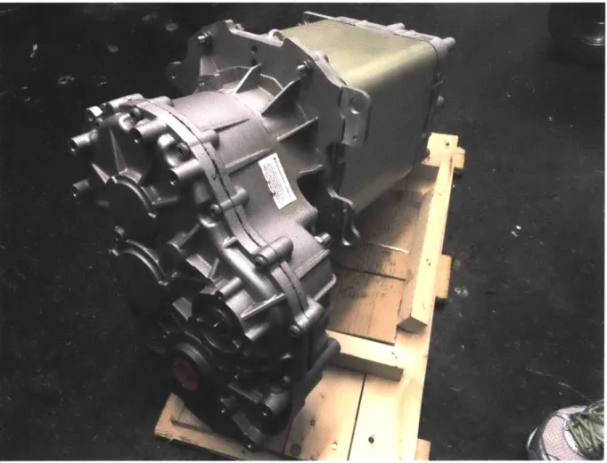
We briefly considered other options for the transmission, such as using the transmission from a much larger vehicle like a truck, or other options such as directly coupling the motor to the to the axles via a chain drive or something similar, but that solution had limited success on previous projects by the team. We ended up choosing to use a Borg-Warner eGearDrive, which was an integrated transmission and differential designed for electric vehicles, and was the same type that was used in the production of the Tesla Roadster. The other benefits of
11 10 5 0 0-0 0 -- 0-0. E a. In 0 400 S300 0 200) cc100 0 40
-Electric vans, which also used the same induction motor, and as such could directly interface to the motor without requiring additional work.
Figure 3: Connected motor and transmission
The transmission was designed to be transversely mounted on the vehicle, and as a rear wheel drive vehicle, the motor would be situated above the rear axle. This also meant that the original suspension of the vehicle could not be used, which led to the thought of changing the type of suspension to that of an independent rear suspension. An additional benefit of this would be, since the motor was already integrated with the transmission and differential, the entire drivetrain and powertrain could be built into a singular unit, which could then be
fit onto the vehicle. This then would be similar to kits used to upgrade vehicles of the same era from the non-independent rear-wheel drive suspension to independent suspensions, which also came in similar modular units.
For batteries we had anticipated using approximately 75 kWh of lithium-ion batteries, which have an approximate energy density of 155 Wh/kg, which would add approximately 480 kg (-1000 lb) of additional mass to the vehicle, although the was offset slightly by the lighter mass of the electric motor. This would lead to an estimate of an empty curb weight of approximately 1300 kg (-2860 lb), with the weight distribution staying approximately the same (52% front, 48% rear).
3. Suspension Design
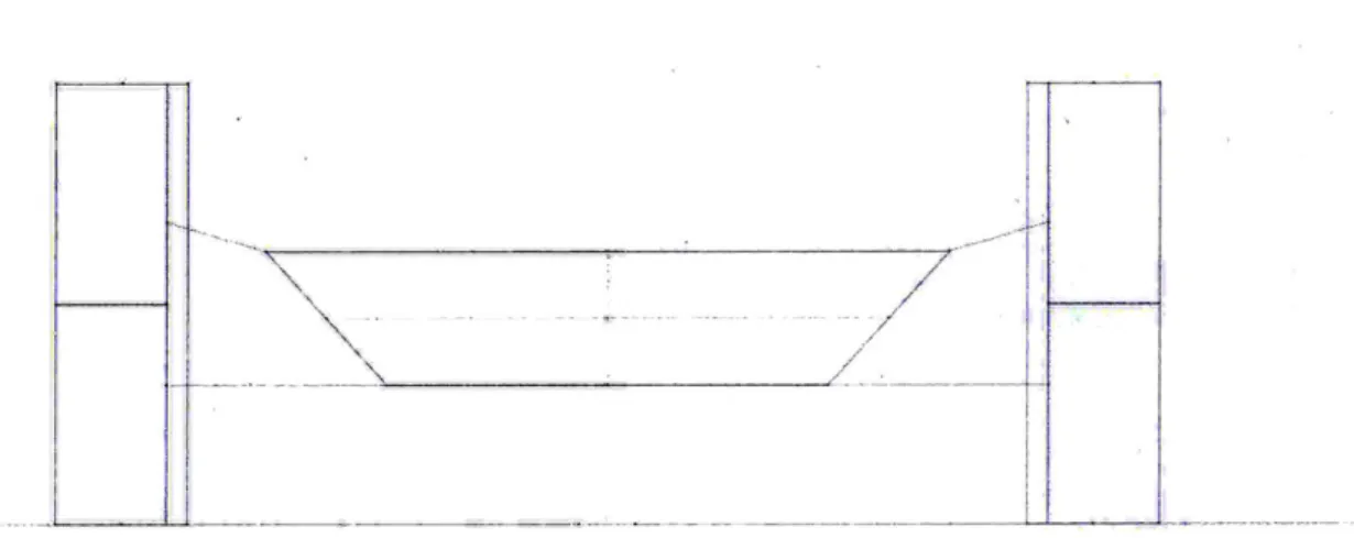
Figure 4: Front view of suspension layout
from the tire also contributing to the lateral acceleration of the vehicle, as well as causing the flexible surface of the tire to roll and deform, which works to create a larger contact patch with the road surface. Other benefits of the double wishbone suspension is the increased flexibility in design.
The positioning of the links (or A-Arms) were chosen by choosing the wheel positions at rest, and at maximum and minimum travel. The three positions were then used to find the inner attachment locations of each wishbone, as seen in Figure 4. The basic characteristics of bump and roll were then able to be determined throughout the entire travel of the wheel. The roll characteristics in particular were chosen to give negative camber with respect to the road surface on the outer wheel in turns, which can be seen in Figure 5, where the arrow indicates the direction of turning.
Direction of Turn
Figure 5: Roll behaviour of the suspension
The springs were chosen by first choosing a desired natural undamped frequency of 1.6 Hz, then matching that to the sprung weight of the rear end, being 0.48 x 1300 kg ~ 620 kg
or 320 kg on each wheel. Then by using the equation
1
fS = - - Hz,
2r W the required wheel rate of 32 N/mm was found.
i
C, 145 140 135 130 125 120 115 110 105 0 Figure 6: 10 20 30 40 50 60Wheel displacement from rest (mm)
Spring length with respect to wheel displacement. The slope of the graph is what is used to determine the motion ratio.
In order to determine the actual value of the springs, the ratio between the amount of wheel travel, and the amount of spring/damper travel, referred here as the motion ratio rm, a motion study was performed in SolidWorks to analyze the relationship between the wheel travel and the spring travel (Figure 6). From the simulation results, the motion ratio was determined to be 0.66. The spring rate and the wheel rate are related by the equation
k
--which by using the values previously found for the motion ratio and the wheel rate, the required spring constant was determined to be 14 N/mm.
Similarly, by choosing a damping ratio of 0.3, we can find the required damping rate by
C = 2( SCWS,
Which gives a damping rate of 3.95 N/mm 2. [1]
4. Subframe Design
The primary challenge in designing the subframe in this study was the relatively small clearances available. The Opel GT has a unibody chassis, and the extra vertical space taken up by the motor and the transmission meant that space had to be cut out from under the rear of the vehicle where the gas tank and the postal shelf used to be located. In addition, the lateral support member that previously held the dampers for the original suspension had to be removed as well, meaning that the subframe would need to replace the function of that member. Another complication was that the length of the motor and transmission were so large, the center of the differential had to be located off center in order for the motor to not be stick into the wheel well of the vehicle, as well as be supported from its rear.
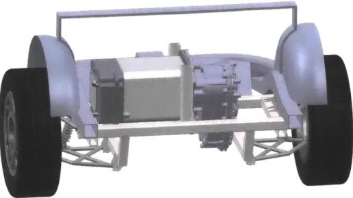
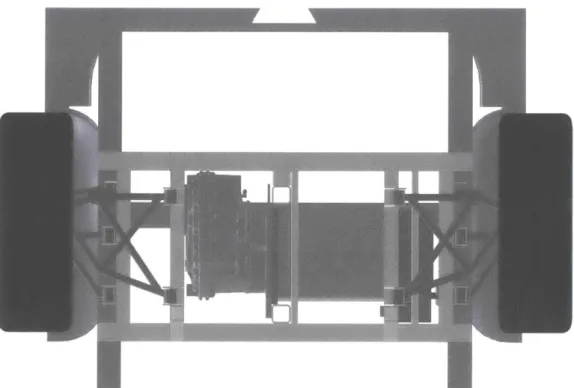
Figure 7: Overall view of the suspension and subframe assembly.
The design of the welded subframe (Figures 7,8) consists of the two main supports that the rear of the vehicle rests on and is fastened to. Connecting the two supports are two underhangs from which the lower wishbone of the suspension is fastened. Going across the two main supports is another crossbeam, sitting just below the frame rails of the chassis. These serve to support the upper wishbone, tie rods, and the upper end of the spring/damper assembly. There are also smaller supports whose function is to support the motor on top of the subframe before it is bolted in. Two beams also rise vertically from the main supports for the interconnect between the motor and transmission to be bolted down. Other mounting plates are located at the rear of the motor; on the transmission next to where the half axles attach, and on the top of the transmission opposite from the motor interface.
Figure 8: Bottom view of suspension and subframe assembly
5. Acknowledgments
I would like to thank several members of the MIT Electric Vehicle Team for their
collaboration with the other systems of the vehicle, and I would especially like to thank Qicheng (Antony) Zhao for creating the CAD mockup of the interior of the Opel GT chassis. I would like to thank Prof. Dan Frey for providing the two Opel GTs we used for design, as well as allowing his own to be used for measurement.
6. References