HAL Id: hal-00707961
https://hal.archives-ouvertes.fr/hal-00707961
Submitted on 14 Jun 2012
HAL is a multi-disciplinary open access
archive for the deposit and dissemination of
sci-entific research documents, whether they are
pub-lished or not. The documents may come from
teaching and research institutions in France or
abroad, or from public or private research centers.
L’archive ouverte pluridisciplinaire HAL, est
destinée au dépôt et à la diffusion de documents
scientifiques de niveau recherche, publiés ou non,
émanant des établissements d’enseignement et de
recherche français ou étrangers, des laboratoires
publics ou privés.
Guidance for Requirements Engineering Processes
Samira Si-Said, Colette Rolland
To cite this version:
Samira Si-Said, Colette Rolland. Guidance for Requirements Engineering Processes. Database and
Expert Systems Applications, 1997, France. pp.1. �hal-00707961�
Guidance for Requirements Engineering Processes
Samira Si-Said and Colette Rolland email {sisaid, rolland}@univ-paris1.fr
Université Paris-1 Sorbonne, CRI, 17, rue de Tolbiac, 75013 Paris, FRANCE
Abstract
Guidance plays a crucial role in requirements engineering as this task is both ill defined and highly intellectual. Guidance can be provided once the goal to be achieved has been identified. Two kinds of guidance are proposed, point and flow guidance. The former supports the fulfillment of goals whereas the latter helps in goal identification. Guidance is driven by guidelines which we have modelled as processes instantiated from a process meta-model just as any other, normal process is. Finally, guidelines are modular. This makes possible the rapid modification of guidelines. The paper presents the two types of guidance, the corresponding guidelines and the tool environment which supports the enactment of guidelines.Introduction
Process engineering is considered today as a key issue by both the Software Engineering (SE) community and the Information Systems Engineering (ISE) community. Process engineering is a rather new research area. Consequently there is no consensus on, for example, what would be a good formalism to represent processes in, or, even, on what the final objectives of process engineering are [ABGM, 93]. However, there is already considerable evidence for believing that there shall be both, improved productivity of the software systems industry and improved systems quality, as a result of improved development processes [Dow, 93], [ABGM, 93], [JPRS, 94].
Guidance plays a crucial role in the Requirements Engineering RE process [RoPr, 94],
[RSM, 95]. This is due, first, to the nature of these processes. RE is a highly intellectual and creative activity. Thus, guidance has to be far more knowledge-intensive than in other activities. The required support is based, for example, on suggestions on how to proceed in a certain situation, or on providing alternatives for achieving a goal. It is clearly beyond the simple automated control of sequences of activities provided by most methods in practice and by process software engineering environments. Second, it is very difficult, if not impossible, for the RE process to progress without guidance. Requirements engineers need to be guided and advised, locally to handle the particular situation they are faced to, and globally, to monitor the flow of decisions they have to make.
Existing CASE tools supporting current ISE methods and SE centred software environments are unable to provide today the kind of heuristics and experience based guidance required in the early phases of system development. CASE tools help in capturing, storing and documenting IS products but do not support RE engineers in their creative development activities [MRTL, 93]. Process-centred software development environments essentially enforce the process performance that conforms to some prescriptive process definition [Dow, 93].
Our guidance approach consists of supporting the RE engineers according to some pre defined process models called ways of working (wow). Ways of working are described
by the instantiation of a process meta model which has been developed within the NATURE1 project. The basic characteristics of this approach is the decision orientation and the strong association between the decision and the situation in which the decision can be made. The process meta model as well as a product meta model are briefly presented in section 1 of the paper.
The second section is dedicated to the detailed presentation of our guidance approach. This approach is implemented in a process centered CARE environment called MENTOR presented in section 3, before concluding.
1. Overview of the process and the product meta models
1.1. Process modeling: a contextual notation
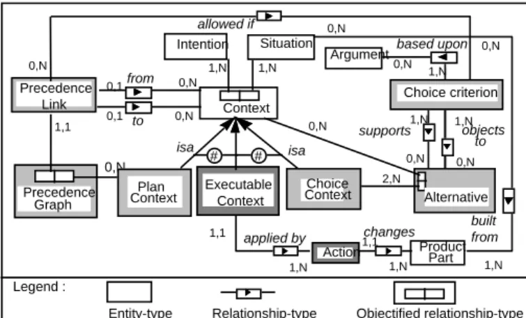
We consider that RE processes are essentially decision oriented. To take into account this characteristics, we have chosen to emphasise the contextual aspect of decisions [RoGr, 94], [Rol, 94]. Our process modelling approach strongly couples the context of a decision named situation to the decision itself. It makes the notion of a context, the coupling of a situation and the intention of decision, central to process modelling (see Fig. 1.).
Legend :
Entity-type Relationship-type Objectified relationship-type
2,N 0,N 1,N 0,1 1,N 0,N 1,N 0,N supports objects to 1,N Alternative Choice criterion Situation Argument allowed if Context built from based upon 0,N 1,N 0,1 0,N 0,N from to 1,1 0,N 0,N Precedence Graph Executable Context
Action Product Part
changes applied by 1,1 1,N 1,N 1,1 1,N 0,N Plan Context # isa isa 0,N Choice Context # Intention Precedence Link
Fig. 1. :Overview of the process meta-model concepts
We distinguish three types of contexts : executable contexts, plan contexts, and choice contexts. This distinction is necessary to handle different granularity levels of contexts. A situation exists at different levels of granularity. Furthermore, decisions have consequences which differ from one granularity level to another. A complete understanding of the notion of a context can thus be gained by articulating the consequences of making the decision of a context on the product under development. We present here a brief description of each of the three contexts.
Executable context
At the lowest level, the RE process can be seen as a set of transformations performed on the product under development. Each transformation results from the execution of a deterministic action which, in turn, is a consequence of a decision made in a certain
1.1. 1 NATURE stands for Novel Approaches to Theories Underlying Requirements Engineering (ESPRIT Basic Project N° 6353).
context. This leads to the introduction of the concept of an executable context.
An executable context expresses the realization of an intention by an action. This action modifies the product under development and eventually generates a new situation subject to new decisions.
Choice context
During requirements engineering processes, engineers may have several alternative ways to fulfill a decision. In order to represent such situations, we introduce the specialization of context into choice context. A choice context allows the exploration of alternative solutions represented in turn as contexts. Each alternative is associated to a set of supporting or objecting statements named arguments which are combined into
choice criteria to support the selection of the appropriate alternative.
Plan context
The last kind of context correponds to decisions which need to be decomposed into more detailed ones. A plan context is an abstraction mechanism by which a context viewed as a complex issue can be decomposed in a number of issues. Each sub-issue corresponds to a sub-decision working on a sub-situation.
The ordering of the component contexts, within a plan, is defined by a graph named
precedence graph (Fig. 1.). There is one graph per plan context. The nodes of this
graph are contexts while the links -called precedence links- define either the possible ordered transitions between contexts or their possible parallel enactment. Based on
arguments, a choice criterion defining when to perform the transition is assigned to a
precedence link.
1.2. Product modeling
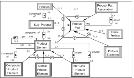
The description of the process can not be dissociated from the description of the product. We have seen before that decision-making relies on a situation observed on a part of the product. In addition to that the realization of a decision is done by the transformation of a part of the product. Fig. 2. depicts the product meta-model [Sch, 93] connected to the process meta-model shown in Fig. 1..
composed of is_a composed of based on target source # # # # # is_a is_a is_a is_a is_a is_a composed of 1,1 0,1 1,N 0,N 1,1 1,N 1,N 0,1 0,N 0,N 1,1 1,1 0,N 2,N is_a gen spe Product Part Product Sub- Product Compound Product Element Atomic Product Element Inter-Link Product Element Product Part Association Product Element Problem Statement Formal Product # # is_a is_a
Fig. 2. : The product meta model
representation of any piece of the product including the whole product, represented by Product in the figure as well as pieces of it, represented by Sub Product and Product
Element. It also allows the construction of views on the product through the concept of Product Part Association. A Product Element can be an Atomic Product Element, if it
can not be decomposed or a Compound Product Element if it can be described using other product elements. Product elements can be related to each others using the concept of Inter Link Product Element. Finally, a Product Part can be either a Formal
Product Part or an informal Problem Statement.
The guidelines supporting the way-of-working of the RE process will be represented as hierarchies of contexts (see [RolGro94] for examples).
2. The guidance approach
As the process is decision-oriented, guidance assumes that there is an intention to be achieved and that help is needed to fulfill it. Our approach proposes two kinds of help (a) help in the satisfaction of an intention and, (b) help in selecting the next intention to make the process proceed. We refer to the former as point guidance and to the latter as flow guidance. These forms of guidance are governed by guidelines which are expressed as hierarchies of contexts (refer to Fig. 1.). In the rest of this section we develop point and flow guidance respectively.
2.1. Point guidance
Point guidance is associated to guidance points. A guidance point pi represented by a
couple (situationi; decisioni) expresses that a RE engineer focuses on a product part (the situation) corresponding to the decision. The set of guidance points represent all situations in which point guidance can be provided.
In order to identify the guidance points we need both the identification of a set of product parts P, and a set of related intentions I. The set of guidance points will be the set of all meaningful combinations from P*I.
Let us construct some guidance points for the Object Model of the OMT [RBPEL, 91] methodology. A partial set of product parts is given in Fig. 3.. These product parts are obtained by the instantiation of the product meta model.
Complementarily, we have identified a set of generic intentions for RE methodologies. These are - Identify : for identifying a product part.
- Attach: for attaching a property to a product part - Describe: for attaching a constraint to a product part
- Construct : for refining a product part by associating its components.
- Validate : for validating a product part. - Complete : for completing a product part
The set of meaningful guidance points is now generated from these intentions and the product parts identified. A sample of these is given below:
<(Pb. St.); Identify_Class>; < (Pb. St); Identify_ Attribute >etc. <(Attribute); Attach> etc.
<(Class); Describe>; <(Association); Describe>; <(Attribute); Describe> etc. <(association); Validate >; <(Class); Validate>; <(Attribute); Validate> etc.
guidance point, that is, the context ci = < situationi; decisioni>. The hierarchy will be progressively constructed by successive refinements of ci. The leaves of the hierarchy are executable contexts which cause product transformation. Fig. 4. illustrates the guideline associated with the guidance point <(Association); Validate>.
is_a composed of target source # # is_a is_a is_a is_a is_a composed of 0,1 0,N 1,1 1,N 1,N 0,1 0,N 0,N 1,1 1,1 gen spe Product Part Sub- Product Compound Product Element Atomic Product Element Inter-Link Product Element Product Element Object model Class Association Inheritance Aggregation Attribute Role instance of instance of instance of instance of
Fig. 3.: Instantiating product parts
The hierarchy refining the context <(Association); Validate> expresses the fact that validation is a complex decision for which several solutions are possible. In our example, there are three alternatives (a) for confirming the association if it is valid (b) for deleting it, if it is invalid and (c) for transforming it to make it valid.
<(Association), Validate>
<(Association), Confirm>
<(Association), Transform>
<(Association), Delete>
<(Association), Change dimension> <(Association), Decompose>
(a) (b)
(c)
(d) (e)
The arguments
a: The association corresponds to the modeled real world phenomenon c: The association corresponds partly to the modeled real world phenomenon b: The association doesn't correspond to any real world phenomenon d: The association relates more or less classes than the ones represented e: The association encapsulates several distinct semantics
Fig. 4. : The point guideline
The transformation decision is itself complex and thus can be refined into two other decisions : The decomposition allowing the explosion of an association into several associations and the change of related classes. Each hierarchy is able to provide local guidance according to the situation described in the guidance point. This guidance is provided by the enactment of the hierarchy of contexts constituting the guideline. At the end of the enactment, a new guidance point has to be selected in order for the process to proceed further. This leads us to introduce the second form of guidance.
Flow guidance provides support to progress from one guidance point to another
under a strategy of development.
A strategy - generally opposed to tactics- is concerned with the way to progress in a process. A stratgey is domain specific. In the software engineering and information system engineering domains, we can find a set of common design strategies like Top down, Bottom up, Inside out strategies [BCNa, 92]. Flow guidance is performed by guidelines based on a number of different startegies. These guidelines help in the selection of the decision to make in the next step before it is resolved.
Flow guidelines are expressed using the same notation introduced in section 1.1. They are hierarchies of contexts. The enactment of a flow guideline supports the RE engineer in the selection of a new guidance point.
An example of a flow guideline is shown in Fig. 5.. It describes how to progress after the identification of an attribute in OM of OMT using the inside out strategy.
<(Attribute:state(attribute)=identified), Progress by inside out strategy>
<(Attribute:state(attribute)=identified) ,
select(<(Attribute); Attach>)> <(Attribute:state(attribute)=identified) ,
select(<(Association);Identify>)>
<(Attribute:state(attribute)=identified) ,
select(<(Class); Identify>)>
<(Attribute:state(attribute)=identified) ,
select(<(Attribute); Describe>)>
Fig. 5. : A flow guideline
The context in Fig. 5. is a choice context with four alternatives. Each of the alternatives proposes the selection of a new guidance point . The choice criteria associated to the alternatives are not shown here.
Every flow guideline corresponds to a possible guidance flow. The identification of guidance flows can be done in two steps :
- first, the set of strategies needs to be identified. Let S be this set.
- second the set of targets, T, of all guidance points has to be identified. The target is the product part resulting from the transformation performed by the point guideline. For instance, for the guidance point, <(Pb. St.), Identify_Class> the target is the Class identified.
T = (target(GPi)), where GPi is a guidance point, 1 i N, and N is the number of
guidance points.
The set of flow guidelines is the meaningful sub set obtained from T S. It expresses the possible transitions between the guidance points using the several identified strategies. The example depicted in Fig. 5. expresses the possible transitions from the guidance point <(Pb. St.); Identify_Attribute> using the inside out strategy.
2.3. Guidance enactment : a spiral view
Guidance of RE processes is obtained by the enactment of guidelines. The two types of guidance are performed in turn to provide continuous support to the RE engineers. To illustrate the enactment, we adopt a spiral view as depicted in Fig. 6..
- choose a guidance point,
- enact the corresponding point guideline, - select the next guidance point.
The selection of the next guidance point is supported by the flow guideline. The two inter-linked forms of guidance are viewed as two intertwined spirals (see Fig. 6.).
Flow guidance
Point guidance
moving from flow to point guidance
moving from point to flow guidance
Strategy selection
Flow guideline selection Flow guideline enaction
Point guideline selection
Point guideline enaction Product transformation
Fig. 6. : A view of guidance enactment
Enactment of flow guidance is viewed as a progression through the four quadrants of a spiral.
During the first quadrant, it is suggested that the RE engineer could select a strategy from a set of suggested strategies. The selection of a strategy will lead to the selection of a guidance flow.
The second quadrant consists of retrieving the flow guideline to support the engineer in the application of the strategy.
The third quadrant aims at enacting the flow guideline to select a guidance point. The fourth quadrant aims at moving to the first quadrant of the lower level, interetwined spiral. This is to provide guidance in the enactment of the selected guidance point.
Enactment of point guidance, is also viewed as a progression through the four quadrants of a spiral.
In the first quadrant, the guideline associated with the selected guidance point is identified.
The second quadrant aims at the enactment of the point guideline. This results in the identification of executable contexts.
The third quadrant transforms the product by executing the executable contexts obtained in the second quadrant.
The fourth quadrant aims at moving to the first quadrant of the higher-level, intertwined spiral. This is to provide flow guidance to select the next guidance point to be enacted.
We have implemented our two level guidance approach in the process centered Computer Aided Requirements Engineering (CARE) environment (section 3).
3. A process centered CARE environment
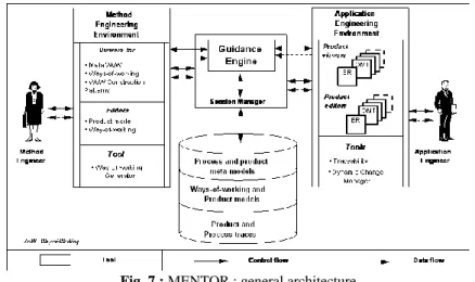
Fig. 7. illustrates the different components of the Computer Aided Requirements Engineering (CARE) environment MENTOR. It provides guidance to both method engineers and application engineers. We will concentrate in this paper on the enactment mechanism : the guidance engine. In addition to its guidance facilities, the environment includes tool such as editors and viewers. In this respect, MENTOR includes the functionality offerred by existing Meta CASE tools (e.g. MetaEdit [SLTM, 91], RAMATIC [BBDG, 89], etc.)
As shown in Fig. 7., the environment is organized in four main components : -the repository to store both ways-of-working and product models (see Fig. 8). -the method engineer environment for guiding method engineers.
- the application engineer environment for guiding application engineers. -the guidance mechanism composed of the guidance engine as the kernel for the whole CARE environment, and the session manager to co-ordinate access to all tools.
Fig. 7.: MENTOR : general architecture
3.1. The repository
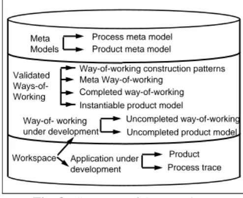
The repository uses the O2 O.O.D.B.M.S. to store and manage data. As shown in Fig. 8., it is structured in three levels :
-the meta level corresponding to the implementation of both process and product meta models as O2 classes.
-the model level corresponding to ways-of-working and product models related to different methodologies.
-the work space level, composed of ways-of-working and product under development.
The Application engineering environment includes a set of specific graphical product
editors and product viewers to develop specifications. A traceability tool and a process change manager are also available.
A product viewer allows a RE engineer to display the current state of a product in a window whereas a product editor provides him means to directly modify the product under development (in the current version of the prototype, tools are available for ER and static OMT specifications, these can easily be extended).
The traceability tool offers means for keeping track of product and process traces. The generated trace can be used for documentation purposes but can also be used as the raw material necessary for later improvement of ways--of-working.
The process change manager aims at keeping coherent the elements used during the enactment of a way-of-working after modifications of the way-of-working.
Workspace Way-of- working under development
Uncompleted way-of-working Uncompleted product model Validated
Ways-of-Working Completed way-of-working Instantiable product model
Product Process trace Application under
development
Process meta model Product meta model Meta
Models
Meta Way-of-working
Way-of-working construction patterns
Fig. 8.: Structure of the repository
Assume an application engineer aborts the execution of a way-of-working and asks a method engineer to modify it. When he resumes guidance then the state of the enacted way-of-working is not anymore coherent towards the updated way-of-working. In this case, the process change manager is automatically triggered.
3.2. The guidance engine
The guidance engine is the set of enactment mechanisms able to guide any process governed by a way-of-working [SiBe, 95]. We use the term enactment, as in the software community, to refer to the fact that the process is performed not only by machines but by the symbiosis of human beings and computers [ABGM, 93]. However whereas software centered environments look at process enactment as program
execution we take the view of process enactment being model interpretation. This
provides more flexibility in human-machine interaction and permits non-determinism. The guidance engine interacts with the process agent to whom it provides guidance based on the process knowledge stored in the way-of-working. In so doing, it controls the incremental construction of the product under development. The guidance engine can be viewed as an active object which interacts with three other kinds of objects : the product under development, the process agent and the process model.
The guidance engine is generic in the sense that it can guide the enactment of any process modeled in terms of the process meta-model we propose. For example, the process leading to the construction of a working (represented in a meta way-of-working) is guided in the same way as the process for constructing a specific application. Obviously the objects interacting in each case are different. During the process of constructing a specific application, the guidance engine interprets the way-of-working to provide advice to the RE engineer (the agent) and to support the construction of the requirements specification. The input is a way-of-working and the output is the RE specification. An example of a guided session within MENTOR environment can be found in [SRG, 96].
4. Conclusion
Our work is directed towards providing guidance in the ill-structured task of requirements engineering. Our claim is, first, that guidance can be provided once the goal to be achieved has been identified. Point guidelines support the fulfillment of such goals. Secondly, we believe that guidance can also be provided for identification of goals. This corresponds to flow guidance and the use of a strategy. Guidance is driven by guidelines which we have modelled as processes instantiated from the same meta-model as any other process. Thus, conceptually, there is no difference between, for example, the guideline as a process and the RE process itself. Finally, guidelines are modular. This makes possible the rapid modification of guidelines. .
We are now working on the extension of the guidance approach and the CARE environment to take into account multi-agent processes.
References
[ABGM, 93] P. Armenise, S. Bandinelli, C. Ghezzi, A. Morzenti, "A survey and assessment of software process representation formalisms", Int. Journal of Software Engineering and Knowledge Engineering, Vol. 3, No. 3, 1993.
[BCNa, 92] C. Batini, S. Ceri, S. Navathe, "Conceptual Data Base Design : an ER approach", Benjamin/Cummings (Pub. ), 1992.
[BBDG, 89] P. Bergsten, J.A. Bubenko, R. Dahl, M. Gustafsson L.A. Johasson : "RAMATIC - a CASE Shell for Implementation of Specific CASE Tools", Tech. report SISU, Stockholm, Sweden, 1889.
[Dow, 93] M. Dowson : Software Process Themes and Issues. In Proceedings of the second International Conference on the Software Process, February 1993.
[FeHu, 93] P. H. Feiler, W. S. Humphrey, "Software Process Development and Enactment : Concepts and Definitions", Proc. 2nd Int. Conf. on "Software Process", 1993.
[JPRS, 94]. M. Jarke, K. Pohl, C. Rolland, J. R. Schmitt, "Experience-Based Method Evaluation and Improvement : A Process Modeling Approach", Int. IFIP WG8. 1 Conference in CRIS series : Method and associated Tools for the Information Systems Life Cycle", North Holland (Pub. ), 1994.
[MRTL, 93]. P. Martiin, M. Rossi, V-P. Tahvainen, K. Lyytinen, "A comparative review of CASE shells - a preliminary framework and research outcomes", published in Information and Management, 25, 1993, pp11-31.
[RoGr, 94] C. Rolland, G. Grosz : A General Framework For describing a Requirements Engineering Process. In proceedings of the Int. conf. on man systems and cybernetics, ICMSC94, san Antonio, Texas USA, October 1994.
[Rol, 94]. Rolland C., "A Contextual Approach to modeling the Requirements Engineering Process", SEKE'94, 6th International Conference on Software Engineering and Knowledge Engineering, Vilnius, Lithuania, 1994
[RoPr, 94] C. Rolland, N. Prakash, "Guiding the Requirements Engineering Process", in the Proceedings of the IEEE Asia-Pacific Software Engineering Conference (APSEC), 1994 [RSM, 95] Rolland C., Souveyet C., Moreno M. "An Approach for Defining Ways-Of-Working", to appear in the Information Systems Jounral in 1995.
[RBPEL, 91] J. Rumbaugh, M. Blaha, W. Premerlani, F. Eddy, W. Loresen : "Object-oriented modeling and design", Prentice Hall international, 1991.
[Sch, 93] J.R. Schmitt : Product Modeling for Requirements Engineering Process Modeling. IFIP WG 8.1 Conf. On Information Systems Development Process 1993.
[SiBe, 95]. Si-Said S. Ben Achour C. : "A Tool for Guiding the Requirements Engineering Process", in Proceedings of the 6th Workshop on the Next Generation of CASE Tools, Jyvaskyla, Finland, pp 23-42,1995.
[SRG, 96] S. Si-Said, C. Rolland, G. Grosz : " MENTOR :A Computer Aided Requirements Engineering Environment", in Proceedings of CAiSE' 96, Crete, GREECE, May 1996.
[SLTM, 91] K. Smolander, K. Lyytinen, V.P. Tahavanainen, P. Martiin : "MetaEdit : A Flexible Graphical Environment for Methodology Modelling", in Proceedings of CAiSE' 91, LNCS N° 498, pp168-193, Tomdheim, Norway, 1991.