HAL Id: hal-02086134
https://hal-amu.archives-ouvertes.fr/hal-02086134
Submitted on 1 Apr 2019
HAL is a multi-disciplinary open access
archive for the deposit and dissemination of
sci-entific research documents, whether they are
pub-lished or not. The documents may come from
teaching and research institutions in France or
abroad, or from public or private research centers.
L’archive ouverte pluridisciplinaire HAL, est
destinée au dépôt et à la diffusion de documents
scientifiques de niveau recherche, publiés ou non,
émanant des établissements d’enseignement et de
recherche français ou étrangers, des laboratoires
publics ou privés.
Distributed under a Creative Commons Attribution| 4.0 International License
Tritium retention in W plasma-facing materials: Impact
of the material structure and helium irradiation
E. Bernard, R. Sakamoto, E. Hodille, A. Kreter, E. Autissier, M.-F. Barthe,
P. Desgardin, T. Schwarz-Selinger, V. Burwitz, S. Feuillastre, et al.
To cite this version:
E. Bernard, R. Sakamoto, E. Hodille, A. Kreter, E. Autissier, et al.. Tritium retention in W
plasma-facing materials: Impact of the material structure and helium irradiation. Nuclear Materials and
Energy, Elsevier, 2019, 19, pp.403-410. �10.1016/j.nme.2019.03.005�. �hal-02086134�
Contents lists available atScienceDirect
Nuclear Materials and Energy
journal homepage:www.elsevier.com/locate/nme
Tritium retention in W plasma-facing materials: Impact of the material
structure and helium irradiation
E. Bernard
a,⁎, R. Sakamoto
b, E. Hodille
c, A. Kreter
d, E. Autissier
e, M.-F. Barthe
e, P. Desgardin
e,
T. Schwarz-Selinger
f, V. Burwitz
f, S. Feuillastre
g, S. Garcia-Argote
g, G. Pieters
g, B. Rousseau
g,
M. Ialovega
a, R. Bisson
h, F. Ghiorghiu
h, C. Corr
i, M. Thompson
i, R. Doerner
j, S. Markelj
k,
H. Yamada
b, N. Yoshida
l, C. Grisolia
a,m aIRFM, CEA Cadarache, Saint Paul lez Durance, France bNIFS, National Institute for Fusion Science, Toki, Gifu, Japan cDepartment of Physics, University of Helsinki, FinlanddForschungszentrum Jülich GmbH, Institut für Energie- und Klimaforschung - Plasmaphysik, Jülich, Germany eCEMHTI, CNRS, Orléans, France
fMax-Planck-Institut für Plasmaphysik, Garching, Germany gSaclay Tritium Lab, CEA Saclay, France
hAix-Marseille University, CNRS, PIIM, Marseille, France iAustralia National University, Canberra, Australia
jCenter for Energy Research, UCSD, La Jolla, CA, United States kJozef Stefan Institute, Ljubljana, Slovenia
lResearch Institute for Applied Mechanics, Kyushu University, Kasuga, Fukuoka, Japan mNational Research Nuclear University “MEPhI”, Moscow, Russian Federation
A R T I C L E I N F O Keywords: Tungsten Helium Tritium inventory Plasma-wall interactions A B S T R A C T
Plasma-facing materials for next generation fusion devices, like ITER and DEMO, will be submitted to intense fluxes of light elements, notably He and H isotopes (HI). Our study focuses on tritium (T) retention on a wide range of W samples: first, different types of W materials were investigated to distinguish the impact of the pristine original structure on the retention, from W-coated samples to ITER-grade pure W samples submitted to various annealing and manufacturing procedures, along with monocrystalline W for reference. Then, He and He-D irradiated W samples were studied to investigate the impact on He-damages such as nano-bubbles (exposures in LHD or PSI-2) on T retention.
We exposed all the samples to tritium gas-loading using a gentle technique preventing any introduction of new damage in the material. Tritium desorption is measured by Liquid Scintillation counting (LSC) at ambient and high temperatures (800 °C). The remaining T inventory is then measured by sample full dissolution and LSC. Results on T inventory on He exposed samples highlighted that in all cases, tritium desorption as a gas (HT) increases significantly due to the formation of He damages. Up to 1.8 times more T can be trapped in the material through a competition of various mechanisms, but the major part of the inventory desorbs at room temperature, and so will most likely not take part to the long-term trapped inventory for safety and operational perspectives. Unfortunately, investigation of “as received” industrial W (used for the making of plasma-facing materials) highlighted a strong impact of the pre existing defects on T retention: up to 2.5 times more T is trapped in “as received W” compared to annealed and polish W, and desorbs only at 800 °C, meaning ideal W material studies may underestimate T inventory for tokamak relevant conditions.
1. Introduction
The distinctive properties of tungsten (W) such as its high sputtering threshold, low induced activation and high melting point[1]drew the
interest of the fusion community, making it a high-profile candidate as a first-wall material for current and future tokamaks. It is used in particular for the divertor where intense heat and particles flux are expected[2]; the latter composed mainly of hydrogen isotopes, deuterium (D) and
https://doi.org/10.1016/j.nme.2019.03.005
Received 13 August 2018; Received in revised form 4 March 2019; Accepted 5 March 2019
⁎Corresponding author.
E-mail address:elodie.bernard@cea.fr(E. Bernard).
2352-1791/ © 2019 The Authors. Published by Elsevier Ltd. This is an open access article under the CC BY license (http://creativecommons.org/licenses/BY/4.0/).
tritium (T) and helium (He). Studies have shown that He drastically af-fects the surface of the material in a large spectra of conditions and even below the threshold for displacement damage in W: dislocation loops, bubbles or W-fuzz can be formed[3]and the question is whether or how those changes impact the material properties, and generally the Plasma Facing Component behavior. In particular, W morphology changes trig-gered by He must be taken into account when considering the material hydrogen inventory[4,5]. Indeed, this property is crucial for the next generation of fusion machines, T being radioactive: its use as the fusion reaction fuel therefore imposes operational and safety limits for quan-tities trapped in the plasma-facing materials. Another key parameter in studying the impact of He irradiation is the temperature: it affects va-cancy and interstitial mobility in the material, and as W surfaces are expected to be heated up to 1000 °C in ITER during operation, it is crucial to integrate this parameter in the study of processes at stake.
The WHIrr (W under Helium Irradiation, cf.Fig. 1) project aims at evaluating and understanding He impact on W and its consequences for the material properties [6], using various irradiation techniques and controlled irradiation temperature (200 to 800 °C). It includes in situ W samples exposures in fusion devices such as the Large Helical Device (LHD), allowing in situ irradiation conditions (in terms of energy and flux distributions) with controlled temperature. Additional He ex-posures are carried on using linear plasma devices to reach a larger range of exposure conditions (in particular flux and fluences) such as PSI-2[7] or PISCES-A[8]. Transmission Electron Microscopy (TEM) was used to evaluate the evolution of W microstructure and highlighted a drastic impact of He on W morphology, notably in much deeper ranges than expected[9]. We coupled this local characterization tech-nique with Grazing Incidence Small Angle X-ray Scattering (GISAXS) to characterize defects created on a larger scale, in particular He bubbles
[10]; and with Positron Annihilation Spectroscopy (PAS), to access to defects at the atomic scale[11]. Once the W samples characterized, hydrogen inventory was measured either using deuterium techniques (D ion beam implantation followed by Temperature Programmed Des-orption (TPD), which allow easy handling of the samples. In parallel, we used tritium gas loading and desorption, which combines the ad-vantages of high sensitivity and tritium-processes relevance, but limits complementary studies of the radioactive samples produced. In this paper, we will address only the T retention study performed on a set of W samples, exposed in LHD or PSI-2 with a preliminary study on the impact of the initial material state on T retention.
2. Experimental set-up and techniques
2.1. W preparation
In order to examine the impact of He irradiation on W structure, a
batch of W samples containing as little pre existing defects as possible is key. We chose high purity (>99.995%) tungsten from Toho Kinzoku Co. Ltd. to prepare 7 × 7 mm2samples with a thickness of 300 µm.
Mechanical polishing was performed in order to get an adequate surface condition for PAS, followed by annealing at 1500 °C for 2 h under va-cuum in order to remove manufacturing-induced defects and con-straints and enhance recrystallization. PAS on a reference annealed W sample (Wref) confirmed that almost no pre existing defect was con-served, and that the samples exposed to He irradiation had a structure close to the perfect lattice of W.
As W components present in tokamaks are neither annealed nor polished, we wanted to add several additional samples of various W providers or preparation methods and investigate how the pre-existing defects interact with T; the results are presented in the preliminary pristine W study.
2.2. He irradiation setups
W samples were exposed during LHD 18th campaign and in the linear plasma device PSI-2 [7]to various conditions of He plasmas. Details on the irradiation conditions are displayed inTable 1: all irra-diations occurred with a temperature controlled sample-holder. Wref
was not exposed and serves as a reference for the initial material state and properties.
In LHD, exposure occurred at the first wall position, where incident particles fluxes are mostly constituted of Charge Exchange (CX) helium. The 3-D neutral Transport code EIRENE[12]is used to estimate the flux and energy profiles for each plasma discharge in LHD. W samples were exposed to a large energy distribution of incident CX He, with low energy He (under 500 eV) being dominant but with incident particles up to 1 keV. Combining those data with the deposition and damages profiles obtained via the simulation code TRIM[13]for each energy of the helium energy spectra, we could estimate the helium deposition and damages profiles created in the tungsten samples (seeFig. 2in[14]for more details).
In PSI-2 we used a sample holder bias of −100 V, resulting in an incident He ion energy of 75 eV, i.e. below threshold energies for dis-placement damage and sputtering yield of He on W. The sample-holder
Fig. 1. Methodology and technique coupling of the WHIrr project.
Table 1
He exposure conditions in LHD and PSI-2.
LHD PSI-2
Exposure CX He (up to 1 keV) 75 eV He+
Temperature (°C) 500–800 250–800
Flux (m−2.s−1) 1 × 10²¹to 1 × 10²² 2.5 × 10²⁰to 2.5 × 10²²
Fluence (m−2) 3 × 10²²to 1 × 10²³ 3 × 10²³to 1 × 1026
E. Bernard, et al. Nuclear Materials and Energy 19 (2019) 403–410
probe combines forced water cooling and electric heating, therefore allowing the adjustment of temperature considering additional heating from the He plasma exposure. This parameter was measured by both an infrared (IR) camera and a thermocouple installed below on of the W samples, allowing crosschecking of the measurement.
2.3. Characterization techniques for He damages
Complementary analyses were used to characterize the changes triggered in the W structure by the He irradiation, in order to under-stand on several scales the modifications of the material morphology. The first characterization is turned toward the micro structure change of the W samples close to the surface, combining Scanning Electron Microscopy (SEM), Transmission Electron Microscopy (TEM) and electron back-scattered diffraction pattern analysis (ESBD); detailed study can be found in[9].
Trapping sites were also evaluated at the atomic scale by Positron Annihilation Spectroscopy (PAS), a non-destructive technique allowing the characterization of defects located close to the surface layer. Measurements were done at CEMHTI laboratory using a beam of mono energetic positrons (e+) with an energy in the 0.5 to 25 keV range and coupled to a Doppler broadening spectrometer [15]. It allows the probing of defects (essentially the ones with a free volume) as a func-tion of depth in the first 700 nm under the surface of tungsten sample. Positrons lose energy by gradually thermalizing in the sample. When they interact with an electron (e-), they annihilate and a gamma ray is emitted around 511 keV; the energy shift from the 511 keV peak is re-presentative of the kinetic momentum distribution of the original e-. Positrons are preferentially annihilated in low electronic density areas, i.e. vacancy-type defects: monovacancies, clusters of vacancies, dis-location loops, and in the case of He-irradiated samples, He bubbles and complexes formed of n vacancies and m He (nV-mHe). Two parameters are used to characterize the gamma ray spectra: the S parameter, the positron annihilation fraction with low momentum electron e.g. va-lence e-, and the W parameter, the positron annihilation fraction with high momentum electron e.g. core e-. More details can be found in[11]. To summarize, the study of the energy of e+ annihilation-emitted gamma rays, by giving an insight on the electronic density experienced by the positron in the sample, is a non perturbative technique able to detect the presence and volume of free defects in the structure of tungsten at the atomic scale.
We also performed Elastic Recoil detection Analysis (ERDA) on a few samples to measure the He content successive to the exposure in PSI-2 or LHD. The experiments were carried at the Tandem Accelerator Laboratory of the Max-Planck-Institut für Plasmaphysik Garching using
a 15 MeV16O5+ion beam. Recoils were detected under 30° in forward
scattering geometry with a solid-state detector with 0.967 msr detector solid angle[16]on a beam spot size of 1 to 3 mm2; after energy and
current measurement calibrations, spectra were analyzed using SRIM stopping powers and cross section for the used reactions were generated by sigma calc as available on the IBANDL website [17] for 16O
(1H;1H)16O, 16O(2H;2H)16O and 16O(4He;4He)16O. These experiments
allowed to compare the respective He inventories depending on the irradiation conditions, most importantly He irradiation type (CX He in LHD or He+in PSI-2).
2.4. Tritium gas loading and inventory
Once He morphology changes were assessed, their impact on T in-ventory was considered. T gas loading was performed at the Saclay Tritium Lab. Several pristine and He-irradiated W samples were studied to investigate whether and to what extent He irradiation of the material had created additional sites for tritium trapping (see[18]for more details on the setup). The native oxide at the surface was eliminated using an active reduction process (see[19]for more details): they were put twice under H2atmosphere for 2 h at 450 °C with a cold trap to
collect the formed H2O. Then all samples were kept 2 h at 450 °C under
1 bar of pure tritium atmosphere, allowing diffusion of T in the sample; the loading procedure is stopped by immerging the sample in liquid nitrogen, therefore freezing all T diffusion in the material until the launch of the desorption study.
Conditions and temperatures of this procedure were chosen in agreement with MHIMS calculations: they predict that for several models of energies and distributions of traps in W (both pristine and after damaging), all the sample volume (i.e. all existing traps) will be accessible for T migration. Yet this model does not include isotopic exchange, and the preliminary H2 reduction step is likely to occupy
hydrogen trapping sites in the materials prior to the tritium loading phase, therefore reducing the tritium trapping and measured inventory. MHIMS simulations highlights that in all the considered cases, the T/H ratio at the end of the loading procedure is about 65%; as isotopic exchange rate between pre-trapped H and T during the T gas loading phase should be constant for all samples as happening at the same temperature, we underestimate this impact similarly in all materials. So, as isotopic exchange was not considered here and will be in-vestigated soon by carrying out a whole procedure using T2also for the
reduction phase, current T inventories should be considered as relative comparison and not quantitative values (as they might be under-estimated).
Tritium desorption is then measured by Liquid Scintillation
counting (LSC) at ambient and then at high temperatures (200–400–800 °C). The tritiated species desorbed from the sample are transported by a carrier gas (air for room temperature desorption, dry air for high temperature desorption) at a controlled flow (30 l/h) up to a bubbling apparatus where distinct feeding bottles accumulate activity desorbed respectively as HTO and HT. The origin of HTO was not in-vestigated in details in this study (work in progress); it is surely linked with surface interaction of T with water (either from the carrier gas or adsorbed at the pipework's surface), but preliminary tests have shown that water excess does not influence the HTO desorption in our ex-periment (we obtained similar desorptions using air from the laboratory or argon). After we desorbed T up to 800 °C, the remaining T inventory is finally measured by sample full dissolution and LSC. Contrary to ion irradiation, no damage or defect are created in the material due to the loading process, preliminary material preparation and previous ana-lyses[9]assessing that defects should not evolve at the temperatures used. The T retention measured is therefore only representative of trapping sites in the materials linked with the original structure and/or He irradiation. Great sensitivity of tritium detection is also key. Ana-lyzing the tritiated species desorbing from the sample (HTO and HT) as a function of time gives an insight of the T quantities initially trapped, the dynamic of the desorption, the nature of the traps. However, the succession of all techniques and sampling uncertainties to reach the final LSC measurement triggers a calculated uncertainty of 10 to 15%. The last step of full dissolution of the samples gives access to the overall tritium inventory in the material. We must point out that our current dissolution method is quite time-demanding for massive W and that all samples are not yet completely dissolved. Therefore, we may be lacking a small part of the total tritium inventory (∼ 1% from previous ana-lysis), and the values presented for the “bulk dissolution” must be taken as preliminary results. However, due to the very small weight of this contribution to the total T inventory for each sample, including the ones for which full dissolution has been reached, we decided to add those data as a very likely tendency.
3. Preliminary study on several W pristine materials
For relevant comparison of the various He irradiated samples in our study, we use one only W provider and identical preparation technique for all our W samples; the reference for the annealed and polish pristine material being called Wref. However, in fusion devices W providers and
manufacturer will be different, and component manufacturing pro-cesses are likely to create or conserve pre existing defects in the W structure. We wanted to investigate this impact by comparing the re-ference sample Wref(from W-1 provider) with i) other W samples from
different providers (providers W-2 and W-3) ii) with various samples
that have experienced different preparation techniques (W-1 as re-ceived from the provider or after annealing). The comparison is un-dertaken by PAS. Fig. 2 presents the normalized S parameter as a function of the normalized W parameters, allowing a comparison for the various pristine W samples: the preexisting defects level decreases from the mono-vacancy SV × WV towards the perfect W lattice
SL× WL.It is noticeable that we have defects present in the structure
even in the highest annealing temperature case (W-3), although logi-cally, it is the closest material from the perfect W structure. It is im-portant to notice that the provider's (and therefore its W manufacturing process) plays a role in the presence of intrinsic defects: in spite of a higher annealing procedure, W-2 (2 h at 1300 °C) still contains more defects than W-1 after 3 h at “only” 1000 °C. The preparation procedure also plays a big part: from a W-1 “as received” loaded with defects, the annealing at 1000 °C for 3 h allows the evolution to a structure a lot closer from the perfect lattice. This first comparative results on W de-fects acting as traps for positrons highlights a crucial point: not all pristine W structure are similar, and both annealing and manufacturing processes play a big part in the presence of defects pre-existing any irradiation in tokamaks.
In order to estimate whether those defects acting as positrons traps will have an impact on tritium retention, we performed identical T gas loading on 3 pristine W materials: one “as received” W directly from our provider; one on an annealed (1500 °C for 2 h) W from the same pro-vider (i.e. the Wref for all the He irradiated study); and one
mono-crystalline W sample.Table 2presents the global inventories for those 3 samples: first, the tritium desorbing as room temperature (as HT or HTO); then, the tritium desorbing at 800 °C (as HT or HTO); and finally, the tritium remaining trapped after desorption at 800 °C, quantity which is measured after full dissolution of the sample and Liquid Scintillation Counting.
The tendency is the same for those 3 contributions: the largest T inventory is always observed on the “as received W sample” (i.e. the industrial W that will compose the plasma-facing materials in toka-maks), followed by the annealed W and lastly the monocrystalline W. The difference is the highest for the 800 °C desorption, which represents 68% of the T inventory in the as received W. 3.5 more T desorbs from that sample at 800 °C compared to the annealed one and 6 times more than for monocrystalline W. These results highlight how crucial the material preparation is when comparing different studies, even before any He irradiation.
4. Impact of He irradiation on T inventory
4.1. Morphology changes caused by He irradiation
W samples from the same batch and preparation process were submitted to several He and D-He irradiation in LHD and PSI-2. Since detailed study and analysis were presented extensively in[6,9–11,14], we will briefly expose an overview of the characterization led mostly by TEM.
4.1.1. Impact of CX He exposure
W samples exposed in the LHD were submitted to fluences of ∼1023m−2and at temperatures ranging from 65 to 800 °C, with a large
energy distributions from a few eV up to 1 keV (see[14]). Dislocation loops and bubbles appeared from the lowest temperature (65 °C). An impressive increase of size (factor 4 to 6) most probably by bubble coalescence is observed as the temperature reaches 600 °C, 500 °C ap-pearing as a threshold for bubble growth. Considering the migration energy in W of 0.06 eV for He and 1.7 eV for vacancy, the 500 °C threshold can be related to the start of vacancy migration in the ma-terials, allowing the formation of bigger He bubbles. Dislocation da-mages formed by He irradiation at high surface temperature appeared as stable until 800 °C, as bubbles and dislocation loops seem to conserve their characteristics.
Table 2
Tritium inventory in various pristine W materials: industrial W “as received”, the same material after annealing and polishing (W annealed), and one monocrystalline W sample. Activity (MBq/mm2) As received W Annealed W Monocrystalline W Desorbed at 20 °C 0.27 0.18 0.17 HTO 76% 95% 65% HT 24% 5% 35% Desorbed at 800 °C 0.60 0.17 0.10 HTO 99% 99% 99% HT 1% 1% 1% Sample dissolution (preliminary*) 0.013* 0.0020* 0.0001* Total 0.88 0.35 0.27 desorbed at 20 °C 30% 51% 63% desorbed at 800 °C 68% 49% 37% remaining >1.44% >0.57% >0.05%
E. Bernard, et al. Nuclear Materials and Energy 19 (2019) 403–410
Cross-sections processed by FIB (cf.Fig. 3) highlighted the forma-tion of a heavily damaged layer at the material surface, with a very high density of dislocation loops and bubbles. Its thickness increases with He fluence and/or exposure temperature, from 12 to 20 nm (seeFig. 8in
[16]). We also observed that bubbles were formed much deeper (70 -100 nm) than this heavily damaged layer at any temperature range: therefore bubbles are distributed deep in W well beyond He im-plantation range (<15 nm), suggesting that He accumulation supports bubble nucleation, without vacancy. The TEM very local analysis to characterize the bubble size and formation was coupled with Grazing-incidence Small Angle Scattering (GISAXS), a non destructive technique combining the length scales of small-angle scattering and surface sen-sitivity of grazing incidence diffraction; the results proved an excellent agreement of the techniques on the bubbles characterization (more details in[9]).
4.1.2. Impact of 75 eV He+exposure
Evolution of the 75 eV He implanted W samples in PSI-2 was ex-posed in details in[9]. In particular,Fig. 1in [8]shows the surface evolution after various flux, fluence and temperature exposures. At low fluence (3.0 × 10²³He.m−2), damage structures between the low and
high flux are similar, with for both cases a slight surface roughness increase at 200 °C, and holes formation (3–15 nm in diameter) at 800 °C. At high He fluence exposure (1.0 × 1026 He.m−2), drastic
modifications of the surface morphology are observed: formation of a nanoscale undulating surface structure with periodic arrangement below 800 °C, creation of holes whose diameter increases with tem-perature; at 1300 °C, a fuzz structure is formed.
Cross-sectional observation by TEM shown onFig. 4highlights the formation of He bubbles just underneath the surface, in the first 10 nm heavily damaged layer. Contrary to CX He exposed samples, less dis-location loops are formed following the He irradiation (most likely due to the fact that 75 eV mono-energetic He+ is much below the
dis-placement damage energy threshold). The thickness of the affected area
does not increase with the temperature: it corresponds to the range of He particle implantation at this energy. He bubble diameter increase significantly as temperature increases from 200 °C to 800 °C, in a good match with the 500 °C threshold identified on the CX He samples.
4.1.3. He content in W irradiated in various conditions
TEM provided precious insight on W morphology changes and highlighted the formation of He bubbles in the material, but could not allow the detection of He contents in the various samples; that is why ERDA was performed on 4 He exposed samples, plus one pristine W sample for reference (seeTable 3). Most of the He appeared to be in the very near surface layer, proving impossible to obtain He profiling using SIMNRA due to depth resolution of the technique at the surface; nevertheless this is in good agreement with the TEM observation, which locates the majority of the He bubbles in the first 10 to 25 nm (de-pending on the incident fluence and energy). Although careful correc-tion to get rid of potential systematic bias was carried out, we will mostly use a comparative approach on those inventories; as expected, the W pristine reference sample did not exhibit any quantifiable He, whereas all He exposed samples do, hence proving that He is indeed present in W after irradiation (as was expected from the PAS analysis –see[10]).
The two samples exposed to 75 eV He+present He contents in the
same order of magnitude (difference of a factor 2). Similarly, the two samples exposed to CX He experience the same helium content but with one order of magnitude increase compare to the 75 He+ implanted
sample, even if the original exposure He fluence were always higher in the case of the 75 eV He+irradiation. More specifically, if we compare
8-A exposed to He+at 1 × 1025He.m−2and 500 °C, and SL2 exposed
to CX He at 1 × 10²³He.m−2and 644 °C, the He content is 3.7 times
higher in the CX He case which is exposed at the lower fluence. The difference in temperature can play a role. It is seen when we compare SR2 and SL2 both exposed to identical conditions except ir-radiation temperature: there is a rather small difference (22%) in He content between the 644 °C and the 778 °C cases, which seems small to explain by itself the order of magnitude observed between 8-A (500 °C) and SL2 (644 °C).
Those first results using ERDA highlight that the He irradiation type (CX vs 75 eV He+) plays a larger role in the He content in W than the irradiation fluence itself. From a material point of view, we indeed saw than the morphology changes and in particular the heavily damaged layer at the surface were different in those two cases, with a thicker affected layer in the CX He irradiation than for He+exposure. This is
linked to the very different energy spectra of incident He (mono-en-ergetic 75 eV He+versus large energy range of CX He with a majority of
low energies but up to 1 keV incident particles). As a conclusion, from a material perspective, the relevant parameter to consider is less the He irradiation fluence than the damage creation profile in the material.
4.2. T inventory in W exposed to He
Once exposed to He and their morphology characterized, a large set of W samples were exposed to an identical T gas loading procedure and desorption study. All inventories obtained are presented in Table 4, with the reference pristine W sample on the left for comparison. Re-producibility of the measurements was validated on the pristine W samples, but the inherent error margins of the loading and desorption analysis techniques triggers a potential variability of the order of 10–15%. An overview of those results highlights that:
1 He irradiation strongly affects the T inventory, with the most sig-nificant uptake occurring on the room temperature desorbed T in-ventory;
2 The worst He irradiation conditions (sample 21A) exhibit a 186% increase in T inventory compared to the pristine reference. It is also observe an increase of tritium inventory of more than 150% for 4
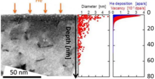
Fig. 3. TEM cross-section image of CX He exposed W (800 °C, 1023He. m−2) on
the left, with dislocation loops appearing as dark areas and He bubbles round and lighter shapes; at the center, the distribution of the diameter of He bubbles counted on the images as a function of the depth; and on the right, the He deposition and vacancy creation profiles as functions of depth estimated from the exposure conditions in LHD (more details for the calculation in[14]). The damage creation of He in W exceeds largely the expected range.
Fig. 4. TEM cross-section image of 75 eV He+exposed W (1.0 × 1026He.m−2,
200 °C on the left and 800 °C on the right): the 10 nm thick heavily damaged layer exhibits the presence of many He bubbles, with a significant increase of diameter as temperature increases.
samples (21A, 20C, SR1 and SL1).
3 On the other hand, sample 21B shows 46% less T inventory com-pared to Wref.
4 Before focusing on the parametric study to distinguish the respective contributions of irradiation conditions, it should be pointed out that one contribution is significantly increased in all He irradiated samples no matter the conditions: the tritium gas (HT) desorbed at room temperature. Although it is very low in pristine W (less than 5%), it can represent up to 80% of the T inventory desorbed at room temperature (6A) and in average 57%. This suggests that He created damages in the structure which acts as a specific trap for T desorbing as HT at room temperature.
We will now isolate the three main parameters of He irradiation, comparing defects detected by positron through PAS analysis and T inventory in several sets of samples (for more details on the PAS data, see [6]). Wref data will always be presented in black for comparison with the original pristine W behavior.
4.2.1. Impact of He flux
Two samples exposed to 75 eV He+(21A in blue and 21B in purple
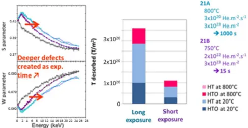
on Fig. 5) were exposed at the same temperature (750–800 °C) and fluence (3 × 10²³ He.m−2) but respectively using low
(3 × 10²⁰He.m−2.s−1) and high flux (2 × 10²²He.m−2.s−1); to reach
the same fluence, the irradiation time was therefore 1000s for 21A and 15 s for 21 B. As He flux increases, i.e. the irradiation time decreases, a thinner area seems affected by traps creation for positrons, and the number of T trapping sites decreases. In other words, as exposure time decreases for a fixed fluence, both free volume of defects in tungsten and T trapping site density decrease, suggesting a diffusional process is at stake, leading to lower T trapping as seen inTable 4.
4.2.2. Impact of He fluence
Two samples exposed to 75 eV He+ (21B in purple and 20C in red onFig. 6) were exposed at the same temperature (750–800 °C) and flux (2 × 10²²He.m−2.s−1) but respectively to low (3 × 10²³He.m−2) and
high fluence (3 × 1025He.m−2); i.e. a 15 s exposure for 21B and 1500s
for 20C. We observe that as He fluence increases, the defects shift deeper in the material and their free volume increases. An increase in the He fluence also triggers an increase in the T retention in the
material, for both 20 °C and 800 °C desorption. If we consider that an increase of He at constant flux is obtained by increasing the irradiation time, once again we confirm that longer exposure time increases both defects in W and T potential traps: He exposure time appears to be the most relevant parameter (rather than He flux or fluence).
4.2.3. Impact of He irradiation temperature
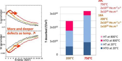
Two samples exposed to 75 eV He+(20C in red and 18A in purple
onFig. 7) were loaded at the same He flux (2 × 10²²He.m−2.s−1) and
high fluence (respectively 3 × 1025He.m−2and 1 × 1026He.m−2) but
at temperature above (750 °C for 20C) and below (300 °C for 18A) the threshold identified for the He bubble growth (in relation with the vacancy mobility in tungsten starting around 500 °C). Fluence is higher for 18A, so we could expect from the results above both free volumes defects and T traps number should increase in that case. But the tem-perature impact takes the lead on the general behavior: as temtem-perature increases, a thicker layer is affected by defect creations on the PAS profiles, and the high temperature sample is also the one exhibiting more T retention.
5. Discussion and conclusions
All He exposed samples, no matter the conditions, exhibited a drastic increase in tritium gas (HT) desorbed at room temperature compared to the pristine reference. This suggests that at least one type of He created damage acts as an additional trap for T desorbing as HT at room temperature. Identifying the specific damage at play is the first priority for the current experiments, although producing samples with only one type of defect is challenging.
For high temperatures, the morphology study highlighted that 75 eV He+exposure and CX He in LHD had clearly distinct impact: in both
cases the heavily damaged layer contains larger He bubbles but in the CX He case this layer gets thicker. The He content measured by ERDA identified more He in the CX exposed samples, and it seems reasonable to think that it is due to the increased volume of bubble-rich layer at the surface. If we focus on samples exposed to similar conditions to either 75 eV He+or CX He, we can observe different tendencies for T
deso-rbing as HTO at 20 °C as displayed inFig. 8:whereas 75 eV He+
irra-diation has no quantifiable impact compared to W pristine reference, the CX exposure creates additional traps for T trapping that will desorb
Table 3
He content measured by ERDA in W exposed to 75 eV He+ (PSI-2) and CX He (LHD).
Sample He exposure Fluence (He.m−2) Flux (He.m−2.s−1) Temp. (°C) He content (He.m−2)
Pristine W / / / / <0.4E+19
20-B PSI-2, He plasma (75ev H+) 3E+23 2.35E+22 200 2.3E+19
8-A PSI-2, He plasma (75ev H+) 1E+25 1.6E+22 500 4.4E+19
SR2 LHD, CX He (up to 1 keV) 1E+23 1E+20 778 1.36E+20
SL2 LHD, CX He (up to 1 keV) 1E+23 1E+20 644 1.66E+20
Table 4
T inventory measured in He exposed W samples.
(MBq/mm2) W ref 21 A 20 C 21 B 18 A 6A SR1 SL1
/ 75 eV He+(in PSI-2) CX He (in LHD)
Flux (s−1.m−2) Pristine W 3E+20 2E+22 2E+22 2E+22 6E+21 1E+20 1E+20
Fluence (m−2) 3E+23 3E+25 3E+23 1E+26 1E+26 1E+23 1E+23
Temp. (°C) 800 750 800 300 650 778 644 20 °C 0.18 0.51 0.52 0.14 0.32 0.42 0.43 0.51 HTO 0.17 0.18 0.17 0.051 0.11 0.084 0.35 0.30 HT 0.0095 0.33 0.35 0.092 0.20 0.34 0.078 0.22 800 °C 0.17 0.14 0.054 0.052 0.13 0.029 0.11 0.072 HTO 0.17 0.13 0.054 0.051 0.12 0.028 0.11 0.069 HT 0.0017 0.0022 0.0006 0.0006 0.0033 0.0007 0.0024 0.0033
Sample dissolution (preliminary*) 0.0020* 0.0003* 0.0003* 0.0010* 0.013* 0.0014* 0.0001* 0.0004*
Total T inventory 0.35* 0.65* 0.575* 0.20* 0.46* 0.45* 0.54* 0.59*
E. Bernard, et al. Nuclear Materials and Energy 19 (2019) 403–410
as HTO. The HT desorption at room temperature (seeTable 4), on the other hand, reaches a much higher level for 75 eV He+samples (20C
and 21A) than for CX He samples (SR1 and SL1): the result is that the global T inventory desorbed at 20 °C is rather close for those 4 samples (and 2.4 to 2.9 times more than for Wref), but with a very different species distribution depending on the irradiation type. This result highlights that the irradiation type, i.e. He damages profile creation in the material, plays a major role in the trapping sites creation for T: as an important consequence, laboratory studies may underestimate T in-ventory if they are not reproducing relevant damages profiles in the studied W samples. Moreover, T desorbing as a different species de-pending on the material irradiation could play a part in nuclear safety for the components use and tokamak operation; more experiments are planned to distinguish the formation process and surface mechanisms in relation with HT and HTO desorption, particularly considering the impact of water vapor in the environment. It is therefore not only the T inventory in the material that is important to consider, but the forms and temperature of its potential desorption; more studies are on-going on this point, with the close consideration of tritium beta decay at the material surface.
Our first results highlighted that it is of prime importance to con-sider not only exposure parameters from the He point of view (i.e. flux, fluence, time, temperature) but from the material perspective (He da-mage creation and implantation profile, He content). To extrapolate for future fusion devices such as ITER, both exposure types are needed, He+ions for the flexibility and larger parameter range allowed in linear
machines, and in situ CX exposures for a more complex but relevant material exposures. We have evidenced that He irradiation and the changes hence triggered in the W structure can significantly increase the T inventory: up to 1.8 times more T can be trapped in the material through a competition of various mechanisms. We will pursue the study investigating more samples (such as W fuzz or WEST exposed samples) and conditions for better understanding of the mechanisms at stake, with a strengthen consideration on the He content and damage profile from the material perspective.
During operation, it seems reasonable to estimate that T desorbing at room temperature will not take part to the long-term trapped in-ventory. As our results point out that most of the He-triggered T addi-tional retention desorbs at room temperature, the impact on opera-tional T inventory should be small. Unfortunately, investigation of “as received” industrial W (used for the making of plasma-facing materials) highlighted a strong impact of the pre existing defects on T retention: up to 2.5 times more T is trapped and desorbs only at 800 °C, meaning ideal W material studies may underestimate T inventory for tokamak relevant conditions. Defects, dislocations, vacancies linked with the manufacturing process and/or sample preparation are therefore key for future extrapolation and modeling of the mechanisms. Isolating the various contributions is difficult but essential for estimation of future inventories in fusion devices, and we are currently working to integrate more W types and providers to our panel, along with attributing the HT and HTO desorption species to their original trapping sites. Our next experiments will also consider a larger range of material preparation,
Fig. 5. Impact of He irradiation flux on damages in the structure detected by PAS (left) and T inventories desorbed in various conditions (right).
from the industrial state used in tokamaks to the ideal structure needed for fundamental mechanisms understanding, integrating the realistic component life cycle such as the impact of conditioning, W oxide or material migration.
Acknowledgments
This work has been carried out within the framework of the EUROfusion Consortium and has received funding from the Euratom research and training programme 2014–2018 under grant agreement No 633053. The views and opinions expressed herein do not necessarily reflect those of the European Commission. We gratefully acknowledge all members of the Saclay Tritium Lab and CEMHTI team for their fruitful help and support.
Supplementary materials
Supplementary material associated with this article can be found, in the online version, at doi:10.1016/j.nme.2019.03.005.
References
[1] G. Pintsuk, Ref. Module Compr. Nucl. Mater. 4 (2012) 551–581. [2] A.-A.F. Tavassoli, et al., J. Nucl. Mater. 302 (2002) 73–88. [3] Y. Ueda, et al., Fusion Eng. Des. 89 (2014) 901–906. [4] V.K. Alimov, et al., Phys. Scr. T 138 (2009) 014048. [5] H. Iwakiri, et al., J. Nucl. Mater. 307-11 (2002) 135–138. [6] E. Bernard, et al., J. Nucl. Mater. 484 (2017) 24–29. [7] A. Kreter, et al., Fusion Sci. Technol. 68 (2015) 8–14. [8] D. Goebel D, et al., J. Nucl. Mater. 121 (1984) 277–282. [9] R. Sakamoto, et al., Nucl. Fusion 57 (2017) 016040. [10] M. Thomson, et al., J. Nucl. Mater. 473 (2016) 6–12. [11] E. Bernard, Phys. Scr. T170 (2017) 014023. [12] M. Kobayashi, J. Plasma Fusion Res. Ser. 7 (2006) 85.
[13] J. Ziegler, et al., The Stopping and Range of Ions in Solids, Pergamon, New York, 1985.
[14] E. Bernard, et al., J. Nucl. Mater. 463 (2015) 316–319. [15] P. Desgardin, et al., Mater. Sci. Forum 363-365 (2001) 523. [16] T.J. Finlay, et al., Phys. Scr. T170 (2017) 014057.
[17] IBANDL database, IAEA, 2017 athttp://www-nds.iaea.org/ibandl/. [18] E. Bernard, et al., Phys. Scr. T167 (2016) 014071.
[19] A. El-Kharbachi, et al., Int. J. Hydrogen Energy 39 (2014) 10525–10536.
Fig. 7. Impact of He irradiation temperature on damages in the structure detected by PAS (left) and T inventories desorbed in various conditions (right).
Fig. 8. T inventory desorbed as HTO at room temperature varies strongly depending on the irradiation type: 75 eV He+samples have a similar inventory than the
pristine Wref, but in spite of the lower He fluence the CX He samples have significantly larger inventories.
E. Bernard, et al. Nuclear Materials and Energy 19 (2019) 403–410
![[PDF] Cours ActionScript : Programmer un menu déroulant | Cours informatique](data:image/gif;base64,R0lGODlhAQABAIAAAP///wAAACH5BAEAAAAALAAAAAABAAEAAAICRAEAOw==)