HAL Id: hal-02263451
https://hal.archives-ouvertes.fr/hal-02263451
Submitted on 4 Aug 2019
HAL is a multi-disciplinary open access
archive for the deposit and dissemination of
sci-entific research documents, whether they are
pub-lished or not. The documents may come from
teaching and research institutions in France or
abroad, or from public or private research centers.
L’archive ouverte pluridisciplinaire HAL, est
destinée au dépôt et à la diffusion de documents
scientifiques de niveau recherche, publiés ou non,
émanant des établissements d’enseignement et de
recherche français ou étrangers, des laboratoires
publics ou privés.
Secure architecture for information systems in avionics
Maxime Lastera, Eric Alata, Jean Arlat, Yves Deswarte, David Powell,
Bertrand Leconte, Cristina Simache
To cite this version:
Maxime Lastera, Eric Alata, Jean Arlat, Yves Deswarte, David Powell, et al.. Secure architecture for
information systems in avionics. Embedded Real Time Software and Systems (ERTS2012), Feb 2012,
Toulouse, France. 7p. �hal-02263451�
Secure architecture for information systems in avionics
Maxime Lastera1,2, Eric Alata1,2, Jean Arlat1, Yves Deswarte1,2, David Powell1,2, Bertrand Leconte3, Cristina Simache4 1CNRS; LAAS; 7 avenue du Colonel Roche, F-31077 Toulouse, France
2 Université de Toulouse; UPS, INSA, INP, ISAE, UT1, UTM, LAAS; F-31077 Toulouse Cedex 4, France 3 AIRBUS, 316 route de Bayonne, F-31060 Toulouse, France
4 ALTRAN Sud Ouest, 4 avenue Didier Daurat, 31700 Blagnac, France
Abstract—Traditionally, software in avionics has been to-tally separated from open-world software in order to avoid any interaction that could corrupt critical on-board systems. However, new aircraft generations need more interaction with off-board systems to offer extended services, which makes these information flows potentially dangerous.
In a previous work, we have proposed the use of virtualiza-tion to ensure dependability of critical applicavirtualiza-tions despite bidi-rectional communication between critical on-board systems and untrusted off-board systems. A comparison mechanism based on execution traces analysis is used to detect discrepancies between replicas supported by diverse virtual machines. We propose to strengthen the comparison mechanism at runtime by the use of an execution model, derived from a static analysis of the java bytecode.
Keywords-avionic information system; dependability; secu-rity; execution model; virtualization;
I. INTRODUCTION
In avionics, each software component has its own level of criticality. This level of criticality is determined according to the severity of the consequences of a fault. For example, a failure on a altimeter, which is used to calculate flight parameters, is more critical than a failure on an entertain-ment component, such as Audio/Video On Demand. If a component performs a critical task, it must be designed and developed in accordance with avionic requirements. The re-liability level of a component depends on several parameters mentioned by Y. Laarouchi et al. in [1]. These include vali-dation, namely development and checking phases, pursuant to security criteria. Therefore, the most critical tasks must have the highest validation level. To obtain this validation level, strict constraints must be respected during design and development phases. Compliance with these constraints makes components costly. On the contrary, it is possible to use commercial off-the-shelf (COTS) components for non-critical tasks and thereby benefit from their lower cost and extended functionalities, compared to avionics grade components.
In this context, the ArSec project explored the possibili-ties offered by diversification and virtualization to improve dependability of architectures based on COTS components. It focuses on a case study of an operator terminal dedicated to maintenance operations. This functionality is currently implemented as a secure on-board computer in the Airbus
A380. Y. Laarouchi et al. in [2] suggest a more flexible use of this secure on-board computer by letting it be mobile and able to interact with the open world. However, this greater flexibility should not degrade the security of the computer. To achieve this purpose, virtualization techniques were used to diversify the execution of maintenance applications by using two separate operating systems (e.g., Microsoft Win-dows and GNU/Linux). Accordingly, a comparison process based on trace analysis ensures the validity of executions. This approach guarantees that all executions are strictically equal. It could be improved considering a static analysis of the application. This analysis is useful to obtain the list of all traces an application generates. Our proposal is to strengthen the process of comparison by the use of an execution model. This paper is organised as follows. Section II presents the context and the motivation of the study. We describe in particular, the different components of the architecture used in the case study. In Section III, we present our approach to create the execution model. Section IV is dedicated to the employed comparison method. Section V shows the means to integrate our solution within the architecture used in the case study. Section VI concludes the paper and presents some future works.
II. CONTEXT AND MOTIVATION OF THE STUDY
The field of maintenance has a large competitive market, worth over 106 billion US$ in 2008 according to a report [3], summarizing the work carried out by Cybel for the PIPAME [4] interdepartmental technology monitoring and forecasting group. Maintenance operations represent an im-portant economic challenge for airline companies since they define the stopover time of the aircraft. Indeed, the aircraft is not allowed to take off without the authorization of ground maintenance operators. If maintenance operations take too much time, the airline company has to pay additional fees to the airport, and incurs additional costs due to the delays of subsequent flights. Large delays can also cause consider-able customer dissatisfaction, which negatively impacts the brand image of the company. Consequently, the shorter this stopover time, the more profitable is the aircraft for the company.
A. Maintenance laptop and virtualization
Nowadays, in flight, the pilot, on-board crew and sys-tems themselves record all faults or unexpected behavior in the On-board Log. In this log, faults are classified according to their criticality. The log is downloaded by the maintenance operators, when the aircraft is parked at the terminal, who analyze the reported errors and failures. Then, the maintenance crew follows the procedures indicated in the manuals to solve them. Traditionally, they interact through a dedicated on-board maintenance computer. To make maintenance more flexible, another procedure has been described by Y. Laarouchi et al. in [2]. The maintenance software installed on the laptop analyzes information flows from error and failure reports, then it specifies the actions to undertake which will resolve errors or failures. As pointed out before, the laptop has not been designed in accordance with the avionic requirements for critical software. So, to allow it to communicate safely and securely with the aircraft information system, a specific intrusion-tolerant software architecture has been proposed [2]. The architecture is based on diversified COTS operating systems supporting replicas of the application software. The basic premise is that an attack targeting a specific operating system (e.g., MS Win-dows) has seldom if ever, an effect on a different operating system (e.g., GNU/Linux). If we compare the behavior of the replicas executed on different operating systems, we should be able to identify a malicious behavior.
As an example of the menace that the approach aims to counter, consider the Stuxnet malware, which Ralph Langner describes as a “cyberwarfare weapon” which can infect any MS Windows PC [5] . Thomas M. Chen and Saeed Abu-Nimeh describe in [6] the method used by Stuxnet to attack a MS Windows PC that programs specific Siemens programmable logic controllers. They present Stuxnet as the largest (in lines of code) and most complex known malware. However, although such a malware has proved to be capable of infecting a specific target (MS Windows OS), it is not designed to attack multiple targets.
The virtualization approach offers a pragmatic way to implement such a diverse operating system architecture on a single machine. Virtualization techniques were introduced for the first time by IBM in the seventies [7] to emulate for a software component the operation of the underlying hardware. Over the last decade, these techniques have been studied with renewed interest and have been developed to offer standardized layers of virtualization. We provide a brief overview of these techniques in the remainder of this section. The virtualization technique consists in offering to a component an abstraction of the underlying layers. For instance, in a multitask operating system, every task has a virtualized view of the hardware layer, since every task considers that it is running alone on the hardware. In our case, we are interested in the notion of a system virtual
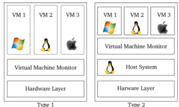
Figure 1. Virtual Machine Monitors (Type 1 and Type 2)
machine [8], which allows many operating systems to be used in parallel on the same physical machine (Figure 1).
Figure 1 represents two types of Virtual Machine Moni-tors (VMMs). Type 1 VMMs (also known as hypervisors) were developed to support different operating systems while running directly over the bare hardware. One example of this type of hypervisor is Xen [9]. Conversely, a Type 2 VMM is installed as an application on a host system, which can then launch and manage different operating systems. Type 2 VMMs are widespread. A typical example would be the use of VMWare on Linux to run a Windows operating system. The virtualization technique offers complete isolation between the different virtual machines, and also provides a means to control the virtual machines through a specific channel. These characteristics can be readily exploited to im-plement the control of the execution of diversified operating systems on a single hardware machine.
B. Architecture of the maintenance laptop
The different components are shown in Figure 2. The software architecture is composed of a hypervisor, two virtual machines and the Java bytecode of the maintenance application. In the case study defined in [10], the Xen hypervisor is used. In [11], we used a benchmark based on a hardware time reference to evaluate the performance of two hypervisors: Qubes [12] and Xen [9]. The results show that the performance degradation induced by the use of either hypervisor is negligible. Of the two, Qubes is shown to be slightly more efficient than Xen. However, in our case study, we chose to keep Xen as the hypervisor because of its maturity and its large user community.
Two virtual machines, each one with a different operating system (MS Windows and GNU/Linux) are managed by Xen. Each operating system executes the same maintenance application. A comparator is implemented on the hypervisor to cross-check the information flows from the two virtual machines. The hypervisor, represented in red, is assumed to have a confidence level higher than the virtual machines, shown in green. We assume that the Java bytecode of the
maintenance application has the same confidence level as the hypervisor.
Figure 2. Architecture of the maintenance laptop
C. Application context
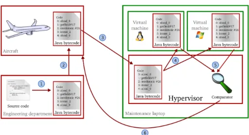
Figure 3 shows the different steps involved in the design, development and deployment of the maintenance application on the diverse architecture. The first step (¬) is carried out by the engineering department and includes the development of the maintenance application within the constraints related to avionics. This application is written in Java [13] to ensure portability towards different target platforms. Once the maintenance application is approved, the Java bytecode [14] of the maintenance application is securely uploaded on the plane (). Next (®), the Java bytecode is securely downloaded to the maintenance laptop. The fourth operation (¯) is the deployment of the Java bytecode on the two different operating systems. It should be remembered that these two operating systems are executed on two virtual machines hosted by the hypervisor. At runtime (°), the graphic calls of the maintenance application are compared. All the events in relation with the graphical library (Java Swing) [15] constitute the execution traces of the mainte-nance application. Events in the two execution traces are pairwise cross-checked after having been received by the comparator. A short delay is allowed between the arrival times of each event in a pair to tolerate differences in execution and data transfer times. An error is detected if the maximum inter-event delay is exceeded or if the events are different. We assume that any such detected error is due to a malicious attack on a virtual machine (although it might also be due to an accidental malfunction). If an error is detected, the execution is stopped, an alert is raised, and all communications to the aircraft are dropped. If the traces are identical, the event is sent to the aircraft, (±).
The foundation of the approach presented by Y. Laarouchi et al.in [10] is the diversification of the environement. In the context of the Java application, a large number of java virtual
machine (JVM) rely on a similar source code provided by Sun Microsystems. In order to detect suspect behavior of the Java application due to a common fault of a JVM, we propose to statically analyse the application. So, in addition to the use of the watchdog, reference to an execution model of the application allows each processing step of the diverse virtual machines to be checked. In the following section, we detail the derivation of an execution model.
III. EXECUTIONMODEL
Currently, attacks are detected by comparing the execu-tion traces of the diversely-executed applicaexecu-tion to identify possible differences. Any difference is considered to be the result of an attack. To prevent the attack from progressing to the information system of the aircraft, the architecture is designed to stop the current execution of the application. However, the lack of any differences between execution traces does not necessarily entail the absence of an attack, i.e., attack detection based on trace comparison alone may have imperfect coverage. In this section, we first propose a refined attack detection process, based on a model of the execution of the application and aimed at providing increased coverage. The idea is to model the execution of the application and to compare observed execution traces with the set of traces admitted by the model. Thus, whenever an attack results in a trace that is invalid with respect to the model, it will be detected. In particular, this additional detection technique can detect some attacks that affect both application replicas, such as when the attack exploits a common vulnerability. We present our methodology for deriving this execution model and show how the architecture is modified to account for the refined detection process. A. Construction of the model
The execution model must represent the set of traces that the correct execution of the application can generate. Before detailing this model, we present the different ways of obtaining it. The required model can be:
1) provided by the engineering department;
2) derived from a formal specification of the application; 3) deduced from the Java bytecode of the application.
The first option presents the advantage of providing a specification of the expected behavior by the software de-veloper, regardless of the implementation of the application. On the other hand, it has the drawback of adding to the workload of engineering department. However, we wish to maintain the transparency of the architecture at this level. In other words, the engineering department in charge of the development of the maintenance application should not have to worry about the presence of the secure architecture. The second option has the same advantages as the first. Its drawback lies in the availability of a formal specification, or the source code. Our architecture should work for any application whether it is delivered with the source code and
Figure 3. Design, development and deployment steps
specifications or not. Consequently, we have opted for the third option : deducing the model from the Java bytecode of the application. Thus, the architecture works regardless of the application. The model represents what the application is and not what the developer wanted it to do. We examine the Java bytecode of the application once it is downloaded on the maintenance laptop, to derive the execution model.
The model is obtained through static analysis of the Java bytecode. The model is represented as a control graph. A control graph is a model used in compilation theory [16] and in decompilation theory [17]. In our case, a node represents a call to the graphics library. An edge between two nodes represents the possibility, for the application, to continue the execution. A node can have many output edges, in particular to represent conditional structures such as if/then/else, while, etc. Conversely, a node can have many input edges, when different branches of conditional structures converge on this node. Although the model is based on static analysis of the Java bytecode, to simplify our illustration of the approach, we consider the source code of the application.
v o i d i n i t ( i n t n , i n t m) { a = new B u t t o n ( ) ; b = new B u t t o n ( ) ; i f ( n == 0 ) { a . s e t V a l u e (m ) ; a . s e t V i s i b l e ( t r u e ) ; } e l s e { b . s e t S i z e ( 2 , 5 ) ; b . s e t V i s i b l e ( t r u e ) ; b . setName ( " i " ) ; } }
Figure 4. Source code
Figures 4 and 5 represent an example of a Java method and the associated graph. This code begins with the declara-tion of the Java funcdeclara-tion, represented by the state q0in green
q0 q1 q2 q3a q3b q4b q6 Button() Button() setValue(m) setVisible(true)
setSize(2,5) setVisible(true) setName(i)
Figure 5. Graph of control
on the control graph. The function continues by the creation of two buttons, represented by states q1 and q2. After the
creation of the second button, the execution can be continued either by invocation of the operation a.setValue(m) or by invocation of the operation b.setSize(2,5), accord-ing to the result of the boolean test used by the conditional structure if. Consequently, two output edges are created on q2 to point to q3a and q3b. Finally, the two branches of the
conditional structure if converge to the final state q6, in red
on the control graph, which represents the end of the control graph associated to this method. There are as many traces that follow the if branch of the control structure as there are different values for the variable m. On the other hand, there is only one trace corresponding to the execution of the elsebranch.
IV. METHOD COMPARISON
In this section, we briefly describe the two methods used before comparing them.
A. Model comparison
As described in Section III, we use the Java bytecode to create our execution model. This model is used to compare each execution of the maintenance application on the virtual
machines. We consider the example of the control graph from Figure 5. Figure 6 represents an execution on one virtual machine. By comparing the current state, the method name and the previous state with those admitted by the control graph we are able to know if the execution is valid or not. For example, in Figure 6, the execution begins with state q0. The Button() method subsequently enables
to go to state q1 then q2. The method setValue(m) is
necessary to reach state q3a. The last method invoked is
setVisible(true) to go from state q3a to state q6.
This sequence of states (q0, q1, q2, q3a and q6) and the
associated methods enable us to validate the execution as being in accordance with the control graph in Figure 5.
q0 Button()q1 Button()q2 setV q3a q6
alue(m) setV
isible(true)
Figure 6. Example of a valid execution
Figure 7 represents an invalid execution. We can see that state q3a is preceded by state q1. This sequence of states (q1,
q3a) is not possible on the control graph in Figure 5, so we
can conclude that this is an invalid execution. Furthermore, to reach state q3a, the method setValue(m) must be
invoked. If another method is invoked to go to state q3a
we can again conclude, according to the control graph in Figure 5, that the execution is invalid.
q0 Button()q1 Button()q3a setV q6
isible(true)
Figure 7. Example of an invalid execution
B. Trace comparison
We recall that the considered execution traces of the main-tenance application consist of calls to the graphic methods. To intercept the graphic methods, we use the ASM library [18], which allows us to add information to the graphic calls and thus facilitate the comparison process. An example of the utilisation of the ASM library is available in [19]. After interception, we obtain a message (or trace event) to send to the comparator. This message contains:
• The Id of the thread in progress; • The unique message number; • The name of the graphic method;
• The list of parameters used.
The messages of the different instances of the application are then compared. In the current prototype, only the message number, the method name and the list of parameters are used. Table I presents an example of a trace consisting of four messages.
T race1 Message number Method name Parameter
new Button() 1 Button null new Button() 2 Button null setValue(12) 3 setValue 12 setVisible(True) 4 setVisible True
Table I TRACE EXAMPLE
Tables II and III show an example of traces from the two virtual machines (VM1 and VM2). T races1 are identical,
so the comparison mechanism validate the trace. T races2
are inconsistent because of the parameter of the method setValue(), the comparator detects the difference and stops the execution of the application. T races3 are not the
same due to the method name compared, the comparison process invalidates this trace.
In the following, we compare the two comparison methods presented earlier in Section IV.
T race1 T race2 T race3
new Bouton() new Bouton() new Bouton() new Bouton() new Bouton() new Bouton()
setValue(12) setVisible(True) setVisible(True) setVisible(True) setValue(12) setValue(12)
Table II
TRACES FROMVM1
T race1 T race2 T race3
new Bouton() new Bouton() new Bouton() new Bouton() new Bouton() new Bouton() setValue(12) setVisible(True) setValue(12) setVisible(True) setValue(666) setVisible(True)
Table III
TRACES FROMVM2
C. Complementarity of the methods
Table IV presents different execution traces which can be observed. T race1 and T race3 are different executions
that activate the if branch. They differ by the value of the parameter m. T race4 corresponds to the activation of the
else branch. As for T race2, it does not match any correct
execution of the method.
These traces correspond to the observation of the execu-tion of the applicaexecu-tion on one virtual machine. At execuexecu-tion time on the diverse architecture, we obtain two traces to
T race1 T race2
new Bouton() new Bouton() new Bouton() new Bouton() setValue(12) setVisible(True) setVisible(True) setValue(12)
T race3 T race4
new Bouton() new Bouton() new Bouton() new Bouton() setValue(13) setSize(2,5) setVisible(True) setVisible(True)
setName(i)
Table IV EXECUTION TRACES
compare, each of which can be T race1, T race2, T race3
or T race4. Table V shows different scenarios related to the
observation of these traces on the diverse architecture. V M1 V M2 V M1× V M2 V M1,2× EM 1 T race1 T race1 4 4 2 T race1 T race2 7 7 3 T race1 T race3 7 4 4 T race1 T race4 7 7 5 T race2 T race2 4 7 6 T race2 T race3 7 7 7 T race2 T race4 7 7 8 T race3 T race3 4 4 9 T race3 T race4 7 7 10 T race4 T race4 4 4
4 Successful comparison 7 Failed comparison
Table V
EXECUTION TRACES COMPARISON
The first two columns correspond to the traces observed on the virtual machines. The third column shows the diag-nosis using trace comparison. The last column corresponds to the diagnosis when comparing the traces with those admitted by the execution model (the abbreviation EM means Execution Model).
The traces generated by the virtual machines, in lines 1, 8 and 10, are identical and correspond to traces that are consistent with the model. Therefore, the diagnosis is ‘no attack’. The other cases correspond to an attack: either the two traces are different or they are not consistent with the model.
Trace comparison is based on the order of arrival and the values observed. It detects all attacks except the case in line 5 (T race2; T race2). As for the comparison of the
trace with the execution model, it identifies the case in line 5 (T race2; T race2) as an attack, but it misses the
detection of the case in line 3 (T race3; T race4) because a
value comparison is needed. These two comparison methods
are thus complementary and enable the detection of all the considered attacks.
V. EXECUTION MODEL INTEGRATION
In this section, we depict how the execution model can be integrated into the architecture presented earlier. Figure 8 illustrates this updated architecture.
Figure 8. Maintenance laptop Architecture
Our focus is still on the maintenance laptop. The first operation (¬) is to create the execution model from the Java bytecode of the maintenance application. Then, this Java bytecode is securely uploaded on the two operating systems (). The third operation (®) consists in the comparison of the traces of the different operating systems. The fourth operation (¯) allows the behavior of each application related to the execution model to be to checked. The decision is based on the results of these two check operations (°). In order to conclude that an execution is valid, it must successfully pass the both checks. Otherwise, a malfunction or a malevolence in the virtual machines is declared. We assume that an attack is taking place. The execution of the maintenance application is stopped, an alert is raised and all communications to the aircraft are dropped.
VI. CONCLUSION
In this paper, we have briefly described some of the results of our research aimed at the improvement of the comparison process in a dual-diverse system by means of an execution model derived from static analysis of the Java bytecode.
It strengthens the existing comparison mechanism using an execution model of the Java application.
Currently, we have identified several directions for further research. First, we plan to take into account the existence of several thread-levels in the execution model. Then, we will examine synchronization routines, which will allow the model to be enriched with a temporal aspect to detect “as early as possible” a case of attack. In particular, a WCET (Worst Case Execution Time) analysis may be useful to improve the accuracy of the model. The third axis is the establishment of a chain of trust that ensures that the architecture is correctly loaded, thus, raising the level of confidence of the architecture.
REFERENCES
[1] Y. Laarouchi, Y. Deswarte, D. Powell, J. Arlat, and E. De Nadai, “Criticality and confidence issues in avionics,” in European Workshop on Dependable Computing, 12th, May 2009.
[2] Y. Laarouchi, Y. Deswarte, D. Powell, J. Arlat, and E. de Nadai, “Connecting commercial computers to avionics systems,” in Digital Avionics Systems Conference, 28th, 2009, pp. 6.D.1â ˘A ¸S1–6.D.1–9.
[3] PIPAME, “Maintenance et réparation aéronautique,” http://www.industrie.gouv.fr/p3e/etudes/etudesprosp.php, Tech. Rep., Jun. 2010.
[4] PIPAME, “Prospective, études économiques et évaluation,” http://www.industrie.gouv.fr/p3e/etudes/etudesprosp.php. [5] R. Langner, “Stuxnet: Dissecting a cyberwarfare weapon,”
Security Privacy, IEEE, vol. 9, no. 3, pp. 49 –51, May-June 2011.
[6] T. Chen and S. Abu-Nimeh, “Lessons from stuxnet,” Com-puter, vol. 44, no. 4, pp. 91 –93, April 2011.
[7] IBM, “IBM: VM history and heritage references,” 1972. [8] J. E. Smith and R. Nair, Virtual machines: versatile platforms
for systems and processes. Elsevier, Jun. 2005.
[9] P. Barham, B. Dragovic, K. Fraser, S. Hand, T. Harris, A. Ho, R. Neugebauer, I. Pratt, and A. Warfield, “Xen and the art of virtualization,” in ACM SIGOPS Operating Systems Review, ser. SOSP ’03. New York, NY, USA: ACM, 2003, p. 164â ˘A ¸S177, ACM ID: 945462.
[10] Y. Laarouchi, “Securités (immunité et innocuité) des archi-tectures ouvertes à niveaux de criticité multiples : application en avionique,” Ph.D. dissertation, INSA de TOULOUSE, Toulouse, Nov. 2009.
[11] M. Lastera, E. Alata, J. Arlat, Y. Deswarte, D. Powell, B. Leconte, and C. Simache, “Characterization of hypervi-sors for security-enhanced in avionics applications,” in SAE AeroTech Congress & Exhibition, October 2011.
[12] J. Rutkowska, Qubes OS architecture, version 0.3, 2010.
[13] J. Gosling, The Java language specification. Addison-Wesley Professional, 2000.
[14] T. Lindholm and F. Yellin, Java Virtual Machine Specifica-tion, 2nd ed. Boston, MA, USA: Addison-Wesley Longman Publishing Co., Inc., 1999.
[15] R. Eckstein, M. Loy, and D. Wood, Java Swing. Sebastopol, CA, USA: O’Reilly & Associates, Inc., 1998.
[16] A. Aho, M. Lam, R. Sethi, and J. Ullman, Compilers: Principles, Techniques, and Tools (2nd Edition). Addison Wesley, 2006.
[17] C. Cifuentes and K. J. Gough, “Decompilation of binary programs,” Software: Practice and Experience, vol. 25, no. 7, p. 811â ˘A ¸S829, Jul. 1995.
[18] E. Bruneton, R. Lenglet, and T. Coupaye, “ASM: a code ma-nipulation tool to implement adaptable systems,” Adaptable and extensible component systems, vol. 30, 2002.
[19] E. Kuleshov, “Using the asm framework to imple-ment common java bytecode transformation patterns,” in 6th Int. Conf. Aspect-Oriented Softw. Develop. (Industry Track),Proceedings, Vancouver, BC, Canada, March 2007.