Abstract –We present an experimental study on the behavior of bubbles captured in a Taylor vortex. The gap between a rotating inner cylinder and a stationary outer cylinder is filled with a Newtonian mineral oil. Beyond a critical rotation speed (ωc), Taylor vortices appear in
this system. Small air bubbles are introduced into the gap through a needle connected to a syringe pump. These are then captured in the cores of the vortices (core bubble) and in the outflow regions along the inner cylinder (wall bubble). The flow field is measured with a two-dimensional particle imaging velocimetry (PIV) system. The motion of the bubbles is monitored by using a high speed video camera. It has been found that, if the core bubbles are all of the same size, a bubble ring forms at the center of the vortex such that bubbles are azimuthally uniformly distributed. There is a saturation number (Ns) of bubbles in the ring, such that
the addition of one more bubble leads eventually to a coalescence and a subsequent complicated evolution. Ns increases with
increasing rotation speed and decreasing bubble size. For bubbles of non-uniform size, small bubbles and large bubbles in nearly the same orbit can be observed to cross due to their different circulating speeds. The wall bubbles, however, do not become uniformly distributed, but instead form short bubble-chains which might eventually evolve into large bubbles. The motion of droplets and particles in a Taylor vortex was also investigated. As with bubbles, droplets and particles align into a ring
structure at low rotation speeds, but the saturation number is much smaller. Moreover, at high rotation speeds, droplets and particles exhibit a characteristic periodic oscillation in the axial, radial and tangential directions due to their inertia. In addition, experiments with non-spherical particles show that they behave rather similarly. This study provides a better understanding of particulate behavior in vortex flow structures.
Index Terms – bubble, droplet, particle, Taylor vortex
I. INTRODUCTION
Bubbles can be found in Taylor vortices during various processes. For example, a careless operation can introduce air bubbles into a liquid system; or small bubbles may be employed for the purpose of visualization of a Taylor vortex [1]. Thus, a study of bubble behavior is of great interest to experimental work. In addition, the mutual bubble-fluid interaction can be an interesting topic in fundamental research.
Shiomi et al. investigated the gas-liquid two-phase flow in a concentric annulus with axial flow. Five major flow regimes were identified: dispersed bubbly, triple-spiral, double-spiral, single-spiral and ring-form flow [2]. Djeridi et al. reported bubble capture and migration in a Couette-Taylor flow [3]. Atkhen et al. presented an experimental study on the highly turbulent Couette-Taylor bubbly flow patterns [4]. Djeridi et al. studied the mutual interactions between dispersed and continuous phases in the Couette-Taylor flow [5]. However, a detailed study of the bubble behavior is still unavailable, due partially to the narrow operating range of the traditional Taylor cells.
In the present study, a viscous liquid layer within a wide gap between two concentric cylinders is adopted to generate the Taylor vortices necessary to trap air bubbles. As a result,
Bubble Behavior in a Taylor Vortex
Rensheng Deng
a,b, Chi-Hwa Wang
a,c, Kenneth A. Smith
a,ba
Singapore-MIT Alliance, b Massachusetts Institute of Technology, c National University of Singapore
Rensheng Deng is with Singapore-MIT Alliance and Department of Chemical Engineering, Massachusetts Institute of Technology, 77 Massachusetts Ave Cambridge, MA 02139, USA
Chi-Hwa Wang is with Singapore-MIT Alliance and Department of Chemical and Biomolecular Engineering, National University of Singapore, 10 Kent Ridge Crescent, Singapore 119260, Singapore
Kenneth A. Smith is with Singapore-MIT Alliance and Department of Chemical Engineering, Massachusetts Institute of Technology, 77 Massachusetts Ave Cambridge, MA 02139, USA
stable bubble structures like rings and chains can be obtained and investigated.
II. EXPERIMENTALAPPARATUS
The experimental apparatus is shown in Figure 1. Mineral oil (with a density of 0.86 g/cm3 and a viscosity of 29.7cp) was adopted as the working liquid within the annulus between a stationary outer cylinder and a rotating inner cylinder (Ri=18.4mm). The inner cylinder is propelled by a motor whose rotation speed can be set continuously between 0 to 800rpm by a computer. The outer cylinder is made of Plexiglas and immersed in a square box filled with mineral oil to eliminate optical distortion. The radius ratio is 0.613 and the aspect ratio is 5.17, with a Taylor number ranging from 11,000 to 680,000.
A syringe pump drives air into the liquid through a slim needle, with the bubble detaching from the needle tip at a certain time interval. The needle is long enough to realize the injection at various positions, and various needle diameters are selected to produce bubbles of different sizes.
A high-speed video camera system is adopted to visualize the bubble flow in the liquid. As shown in Figure 1, a lamp with the power of 50W/100W is used to illuminate the flow field. Images of the bubble can be captured by the camera at a frame speed of 250fps and then sent to a computer for further real-time processing. Furthermore, the liquid flow is monitored using a 2-D PIV system, by which the position, shape and velocity distribution of the Taylor vortices can be determined.
III. RESULTS AND DISCUSSION
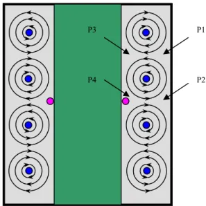
As shown in Figure 2, bubbles are found at two locations: one is in the core of the Taylor vortex (“core bubble”), and the other is closely attached to the inner cylinder (“wall bubble”). No differences are found between the core bubbles in the clockwise and anti-clockwise vortices. However, the wall bubbles are found only in the outflow regions along the inner cylinder (shown by P4 in Figure 2), while positions denoted by P1, P2 and P3 are not favored. This may be attributed to the fact that pressure dominates among the various forces on the bubble [1], and P4 corresponds to the lowest pressure according to the pressure distribution calculated by Atkhen et al. [4]
3.1 Core bubbles
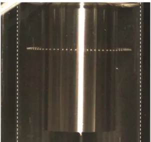
When bubbles of the same size are injected into a certain vortex core, a bubble ring forms at the center of the vortex such that bubbles are azimuthally uniformly distributed. Figure 3 shows a picture of a ring consisting of 61 bubbles. It should be noted that the ring actually circulates in the same direction as the inner cylinder. The circulating speed is found to be lower than the rotation speed of inner cylinder ΩRi and increases with increasing Ω. A detailed investigation also shows it is independent of the number of bubbles forming the ring. A smaller circulating speed is observed for larger bubbles.
Also, there is a maximum number of bubbles that can be trapped in the ring, which is called the saturation number, Ns. In the state of saturation, the introduction of an additional bubble can break the ring structure: the newcomer can not settle
Figure 1 Schematic diagram of experimental apparatus (1) motor (2) outer cylinder (3) working liquid (4) inner cylinder (5) needle (6) lamp (7) camera (8) computer for motor (9) syringe pump (10) computer for high-speed video camera 1 2 3 4 5 6 7 8 9 10 P1 P2 P3 P4
down even after a long time and it finally coalesces with one or two bubbles in the ring to form a large bubble, thus the ring is no longer uniform in bubble size. The saturation number is found to be dependent on the bubble size dp and the rotation speed Ω. For example, at a fixed Ω of 300rpm, Ns has a value of 71 for dp=1.76mm, while 150 bubbles with the diameter of 1.24mm are needed to saturate the same orbit. On the other hand, for the same bubble size, a higher Ω corresponds to a higher value of Ns, but the relationship is not linear – dNs/dΩ monotonically decreases with increasing Ω.
One may wonder what happens if two bubbles with different sizes travel in the same orbit. It is observed that the smaller bubble (BS, dp=1.24mm), having a higher circulating speed as stated above, moves faster than the large one (BL, dp=1.95mm), and soon BS catches up with BL. Because BS is subjected to a smaller buoyancy force, it holds a slightly lower vertical position than BL does. Then, BS overpasses BL from the below and moves ahead, followed by the next chasing-overpassing game. However, the crossing between the large and small bubbles does not continue indefinitely – the difference in circulating speeds becomes less and less significant until finally a final state is reached in which these two form a stable ring structure.
3.2 Wall bubbles
When a bubble is injected near the wall, it can be trapped at outflow regions as a wall bubble. The wall bubble travels much faster than the core bubble, and a careful measurement shows that the
angular speed of the bubble, ω, is proportional to Ω. However, although the bubbles are closely attached to the inner cylinder, ω is still lower than Ω (for example, for a bubble with the size of 1.3mm, the slope of the ω vs. Ω line is 0.91), showing some kind of “slipping” motion here.
The addition of wall bubbles with a uniform size does not induce the occurrence of a ring; instead a chain structure forms. The newcomer, no matter where it is introduced initially, slides along the inner cylinder wall until it meets the already existing bubble in the orbit. The two bubbles then move together as a chain with a very short gap between them. However, such chains are stable only at low rotation speeds and for small numbers of bubbles. If many bubbles exist in the same chain, some of them tend to coalesce into large bubbles and even escape from the orbit if their sizes are large enough. Therefore, long bubble chains are not observed after stabilizing the system for a long enough time. Also, an increase in Ω promotes the bubble-coalescence behavior in the chain. This is different from the observations of Atkhen et al. [6] and Djeridi, et al. [3], where long ribbons formed near the wall due to the continuous suction of bubbles from the free surface.
3.3 Droplets and particles
By analogy, droplets and solid particles might be expected to behave much like bubbles. However, besides the significant differences in physical properties like density, viscosity and surface tension, they may also differ in deformability. Like bubbles, droplets can deform but solid particles are completely rigid. Thus, it is of interest to examine the effects of such differences on their behavior when trapped in Taylor vortices. In the present study, water (ρ=1.0g/cm3) was adopted to generate droplets in the mineral oil system, and glass beads with a density of 2.5g/cm3 were used as particles. Note that, unlike bubbles, both the droplets and the particles are heavier than the mineral oil and they would sink were it not for the formation of the Taylor vortices.
It can be observed that, at high rotation speeds (e.g., 600rpm), the particles (2.0mm in diameter) exhibit a “dancing” behavior: the trajectory of circulation around the inner cylinder is not purely azimuthal. Instead, the particles exhibit a characteristic periodic oscillation in the axial, radial and tangential directions. The reason for this is still unknown, but by no means can it be attributed to a change in flow pattern: the PIV results show that the flow is still in the Taylor
Figure 3 A bubble ring composed of 61 core bubbles of the same size. The dashed lines show the inner wall of the outer cylinder, and the white wide stripe is the reflection from the inner cylinder.
vortex regime. Such a “dancing” behavior becomes less significant with decreasing rotation speed. At Ω=300rpm, the trajectory is purely azimuthal.
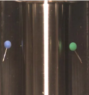
The motion of non-spherical particles is even more complex. Various shapes were tested: ellipsoids and both circular and ellipsoidal cylinders, etc. Figure 4 shows the motion of two pushpins captured in a Taylor vortex. At high rotation speeds all these particles show the “dancing” behaviors described above at high rotation speeds. Due to their asymmetric shape, they also perform various motions of “self-rotation” as a result of the unbalanced torques.
For droplets, one characteristic phenomenon is that they deform at high rotation speeds but remain spherical at low rotation speeds. As for solid particles, they are never found to stay near the inner cylinder wall. And, no long rings can be observed – excess droplets/particles sink from the orbit although no coalescence behavior appears as found in the bubble system.
IV. CONCLUSION
Bubbles, droplets and particles can all be trapped in Taylor vortices, and the trajectories are fascinating. Although some experimental results can be explained readily, more experimental and theoretical work must be carried out to understand the system better, for example, starting from a simple question, “why are core bubbles of the same size uniformly distributed in the orbit?”
ACKNOWLEDGEMENTS
This project is supported by MIT under the grant 6895606, National University of Singapore under the grant R-279-000-095-112 and Singapore-MIT Alliance under the grant C-382-427-003-091. Part of the work has been presented at the 2004 AIChE Annual Meeting, November 7-12, Austin, TX, USA.
REFERENCES
[1] Batten W. M. J., Tumock S. R., Bressloff N. W., Abu-Sharkh S. M. Turbulent Taylor-Couette vortex flow
between large radius ratio concentric cylinders.
Experiments in Fluids, 36:419-421, 2004.
[2] Shiomi Y., Kutsuna H., Akagawa K., Ozawa M.
Two-phase flow in an annulus with a rotating inner cylinder (flow pattern in bubbly flow region). Nuclear
Engineering and Design, 141: 27-34, 1993.
[3] Djeridi H., Fave J-F, Billard J-Y, Fruman D. H. Bubble
capture and migration in Couette-Taylor flow.
Experiments in Fluids, 26: 233-239, 1999.
[4] Atkhen K., Fontaine J., Wesfreid J. E. Highly turbulent
Couette-Taylor bubbly flow patterns. Journal of fluid
mechanics, 422: 55-68, 2000.
[5] Djeridi H., Gabillet C., Billard J-Y Two phase
Couette-Taylor flow. C. R. Mecanique, 330: 113-119, 2002.
[6] Atkhen K., Fontaine J., Aider J. L., Wesfreid J.E. Air
bubbles in a Couette-Taylor flow. C. R. Acad. Sci. Paris,
327, Serie II b, 207-213, 1999.
Figure 4 Capture of non-spherical particles in the Taylor vortex