Publisher’s version / Version de l'éditeur:
Vous avez des questions? Nous pouvons vous aider. Pour communiquer directement avec un auteur, consultez la
première page de la revue dans laquelle son article a été publié afin de trouver ses coordonnées. Si vous n’arrivez pas à les repérer, communiquez avec nous à [email protected].
Questions? Contact the NRC Publications Archive team at
[email protected]. If you wish to email the authors directly, please see the first page of the publication for their contact information.
https://publications-cnrc.canada.ca/fra/droits
L’accès à ce site Web et l’utilisation de son contenu sont assujettis aux conditions présentées dans le site LISEZ CES CONDITIONS ATTENTIVEMENT AVANT D’UTILISER CE SITE WEB.
1st International Conference on Technological Advances in Podded Propulsion
[Proceedings], 2004
READ THESE TERMS AND CONDITIONS CAREFULLY BEFORE USING THIS WEBSITE. https://nrc-publications.canada.ca/eng/copyright
NRC Publications Archive Record / Notice des Archives des publications du CNRC : https://nrc-publications.canada.ca/eng/view/object/?id=2309fa42-6248-4cb2-8e05-a6d3458cac3f https://publications-cnrc.canada.ca/fra/voir/objet/?id=2309fa42-6248-4cb2-8e05-a6d3458cac3f
NRC Publications Archive
Archives des publications du CNRC
This publication could be one of several versions: author’s original, accepted manuscript or the publisher’s version. / La version de cette publication peut être l’une des suivantes : la version prépublication de l’auteur, la version acceptée du manuscrit ou la version de l’éditeur.
Access and use of this website and the material on it are subject to the Terms and Conditions set forth at
Numerical investigation of propulsive characteristics of podded
propeller
Islam, M.; Taylor, R.; Quinton, J.; Veitch, B.; Bose, N.; Colbourne, D. B.; Liu,
P.
NUMERICAL INVESTIGATION OF PROPULSIVE CHARACTERISTICS OF PODDED PROPELLERS
Mohammed Islam, Rocky Taylor, Justin Quinton, Memorial University, Canada Brian Veitch, Neil Bose, Memorial University, Canada
Bruce Colbourne, and Pengfei Liu Institute of Ocean Technology, Canada
Numerical investigations were performed to predict effects of propeller hub taper angle and pod geometry configurations on propulsive performance. An existing time domain panel method code was extended to handle the simulation tasks. The effect of taper angle was examined in terms of shaft thrust coefficient, KT, and torque coefficient, KQ, for different taper angles of -15°
(pull/tractor configuration) and +15° (push configuration). The predicted pressure distribution was also analyzed to investigate the effect of taper ratio on pressure coefficient, Cp, at the blade root
section. The effects of pod-strut geometry on KT and KQ of a propeller with taper angles of 15° and
20° with two pods both in push configuration were examined. A complementary experimental study of the effects of taper angle on propulsive performance was also conducted for 15° and 20° taper angles in push configuration. Numerical predictions and experimental measurement showed a good agreement over a wide range of advance coefficients from the bollard pull condition to the design advance coefficient of about 1.0.
1 Introduction
A research program on podded propellers is being undertaken jointly by the Ocean Engineering Research Centre (OERC) at Memorial University, the National Research Council’s Institute for Ocean Technology (IOT), Oceanic Consulting, and Thordon Bearings. The program combines developments in numerical prediction methods with parallel developments in experimental apparatus. Amongst the hydrodynamic issues that have been identified are questions regarding the effects of hub taper angle, pod-strut interactions, gap pressure, and pod-strut geometry on podded propeller performance. Some fundamental investigations are required to fill these research gaps.
This paper presents the findings of a numerical study on the effects of propeller hub taper angle and pod-strut geometry in push configuration on propulsive performance. In addition, the results of a complementary experimental study on open water propulsive characteristics of two model propellers with taper angles of 15° and 20° are included to validate the numerical predictions. An overview of the model propeller and the pod-strut geometry that were used, and a brief description of the experimental set-up are also provided. Included with the results are some predictions of the effect of hub taper angles on pressure distribution at the blade root section and the effect of pod geometry on the performance for push configurations.
Facinelli and Muggeridge [1] provided a brief introduction to podded propulsion system and suggested a way of designing podded ship propulsors. Mewis [2] conducted open water tests of pod units and analyzed Reynolds number effects and gap influence on measured thrust of the pod units. He showed that the pod unit (pull configuration) has about a 5% lower efficiency than a unit consisting of an identical propeller with a rudder. Rains and Vanlandingham [3] examined some hydrodynamic issues such as pod/strut drag and propulsive efficiency for different pod configurations. Karafiath and Lyons [4] analyzed propeller wake data and powering data for podded propellers of various configurations to examine the inflow effects on propeller hydrodynamic and powering performance, respectively. Terwisga et al. [5] also discussed some general hydrodynamic and design issues related to pods. Kurimo [6] did some model scale as well as full-scale tests on the
propulsive performance and manoeuvring characteristics of the podded propulsors on the cruise ship M/S Elation. He observed good powering performance and superior cavitation performance of the podded propulsors with the puller arrangement. Toxopeus and Leoff [7] discussed some manoeuvring aspects of fast ships with pods and compared the manoeuvrability between ships designed with conventional propulsion and pod propulsion and highlighted the benefits and points of attention. They also provided some design guidelines to improve the manoeuvring performance of a ship with a pod propulsion system. Chen et al. [8] did some powering and cavitation experiments on a contra-rotating (CR) propeller designed with a tractor pod for a high-speed patrol boat. The authors showed that the pod-mounted CR propeller gave a 28% reduction in power consumption at design speed with a 7 knots improvement in cavitation inception speed.
2 Numerical Cases and Experimental Setup
2.1 Propeller Geometry
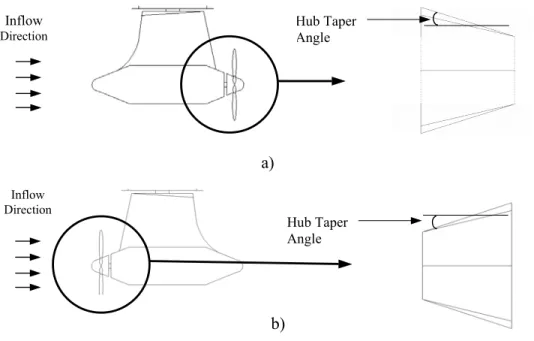
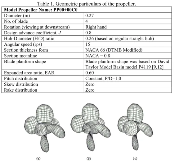
One aspect of propellers designed for podded propulsors that distinguishes them from conventional screw propeller design is that of the propeller hub geometry and the associated blade root-hub interface. Since it is necessary to have a smooth transition between the adjacent faces of the propeller hub and the pod body, it is a necessity to have a conical hub profile as illustrated in Figure 1 shown below. Depending on the hub diameters at the leading and trailing edges of the propeller and the length of the conical hub, the propeller hub will have different taper angles. The particulars of the model propeller used in both the numerical and experimental tests are outlined in Table 1.
Figure 1. Podded propeller configurations:
(a) push mode (positive hub taper angle); (b) pull mode (negative hub taper angle).
Hub Taper Angle Inflow Direction Hub Taper Angle Inflow Direction a) b)
An existing panel method [9] code, PROPELLA was modified to enhance the capabilities to handle the geometry of tapered propeller hub along with the pod-strut structure based on the method as described in [10]. The propeller geometry illustrated in Figure 2 was generated with post processing software [11] using geometric data created and imported by the modified PROPELLA code. Here positive hub angle represents push mode propellers, which have an increasing diameter in the upstream direction. The model propellers shown below include a baseline cylindrical hub section with no taper angle (regular straight hub), a push mode propeller with positive hub taper angle, and a pull configuration propeller with negative hub taper angle.
Table 1. Geometric particulars of the propeller.
Model Propeller Name: PP00+00C0
Diameter (m) 0.27
No. of blade 4
Rotation (viewing at downstream) Right hand Design advance coefficient, J 0.8
Hub-Diameter (H/D) ratio 0.26 (based on regular straight hub)
Angular speed (rps) 15
Section thickness form NACA 66 (DTMB Modified)
Section meanline NACA = 0.8
Blade planform shape Blade planform shape was based on David
Taylor Model Basin model P4119 [9,12]
Expanded area ratio, EAR 0.60
Pitch distribution Constant, P/D=1.0
Skew distribution Zero
Rake distribution Zero
Figure 2. Mesh view of the model propeller geometry:
(a) 0° hub angle (regular straight hub); (b) 15° hub angle (push configuration); (c) -15° hub angle (pull/tractor configuration).
2.2. Pod-Strut Geometry
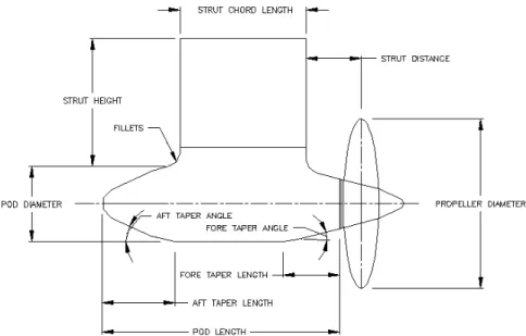
Prior to developing a numerical model of the pod, it was first necessary to define the geometry of the pod shell and strut in terms of a general set of geometric parameters. The geometric parameters identified as being important in the definition of the pod geometry are identified in Figure 3 below [13]. Once the parameters had been identified, the corresponding model pod geometry files were constructed using the parametric values indicated in Table 2 below. The pod-strut geometry illustrated in Figure 4 was generated with the post processing software using geometric data created and imported by the modified PROPELLA code. Here two pod-struts in push configurations were modelled using the parametric values indicated in Table 2.
Figure 3. Geometric parameters used to define model pod geometry. Table 2. Geometric particulars of the pod shells.
Parameters Pod #1 Pod #2
Pod Diameter 139 mm 139 mm
Pod Length 410 mm 410 mm
Strut Height 300 mm 300 mm
Strut Chord Length 225 mm 225 mm
Strut Distance 44 mm 44 mm
Strut Width 60 mm 60mm
Fore Taper Length 85 mm 85 mm
Fore Taper Angle 15 o 20 o
Aft Taper Length 125 mm 125 mm
Aft Taper Angle 25 o 25 o
Fillets 50 mm 50 mm
Figure 4. Mesh view of model pod-strut geometry in push configuration: (a) Pod #1; (b) Pod #2.
2.3 Experimental Set-up
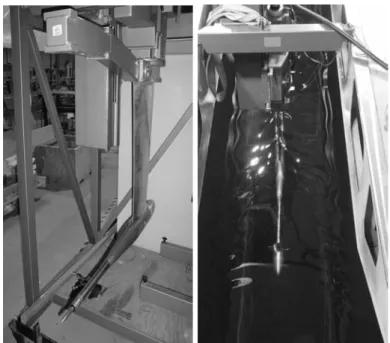
The objective of the experiments described in this paper is to provide a baseline evaluation of propellers designed for pod units operating in the open water condition without the presence of the pods. These tests also serve to provide data to assist with the validation of numerical predictions. The experiments were conducted in the towing tank facility at the Institute for Ocean Technology (IOT) using the Kempf & Remmers Dynamometer depicted in Figure 5 below. This instrumentation package allows for the measurement of propeller thrust and torque data over a range of advance coefficients.
When testing a push mode, conical hub propeller in the open water condition, it is necessary to use a large, bulbous nose cone to provide suitable inflow conditions to the propeller. These nose cone adapters, illustrated in Figure 6 below, were designed in accordance with the applicable ITTC guidelines [14] for open water tests and podded propellers.
Figure 5. Kempf & Remmers dynamometer: in test frame (left) and in the tow tank (right).
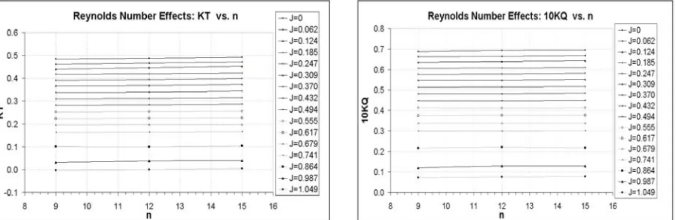
The operating rotational speed used for these experiments was selected based on data collected from a preliminary set of experiments to look for viscous effects. These were conducted by measuring thrust and torque at specific J values over a range of rotational speeds to ensure the propeller was producing consistent results. The KT and 10KQ results were plotted as a function of rotational speed, n, for each J value as illustrated in Figure 7 below. The final selected rotational speed used in these tests was 15rps.
Figure 7. Reynolds number effects on (a) Thrust coefficient, KT and (b) Torque coefficient, KQ.
3. Results and Discussion
3.1. Effect of hub taper angle
The measurements collected from the experiments were analyzed in terms of thrust coefficient,
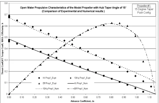
KT, torque coefficient, KQ, and open water efficiency, against advance coefficient, J. In Figures 8 and 9 the numerical predictions are shown along with the experimental results for the taper angles of 15° (Prop #1) and 20° (Prop #2), respectively, in push configuration. For the computations, the number of chordwise and spanwise panels for all blades was taken as 16 and 12 respectively. This comparison shows very good agreement from the bollard pull condition (zero advance coefficient) to the design load condition (advance coefficient, J=0.80). The numerical predictions diverged from the measurements for advance coefficients higher than the design advance coefficient. This may be due to flow separation caused by the pressure gradient at the trailing edge along the root hub.
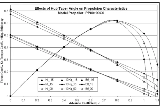
The numerical predictions to evaluate the effect of hub taper angle on the performance of the propeller are shown in Figure 10 in terms of KT and KQ against J for taper ratios of 15° push and 15° pull configurations. Similar trends were found for other taper angles, so they are not included in the figure. From Figure 10 it is apparent that hub taper angle has more influence on KT and KQ at highly loaded conditions (low J value) than for lightly loaded conditions (high J value). For the same 15° hub taper angle, the push configuration propeller produced less thrust, especially for low J values, than the pull configuration propeller. Quantitatively, in the bollard pull condition (zero advance coefficient) a decrease of 3.5% in thrust coefficient and 3.2% in torque coefficient were predicted for the push configuration propeller (+15° hub taper angle) as compared to the straight-hub propeller. On the other hand, in the bollard pull condition an increase of 1.2% in thrust coefficient and 2% in torque coefficient were predicted for the pull configuration propeller (-15° hub angle), compared to the straight-hub propeller. Alternatively, it can be said that in the bollard pull condition, an increase of 4.7% in thrust coefficient and 5.2% in torque coefficient occurs for the 15° pull configuration propeller compared to that of a 15° push configuration propeller. The panel method code, being a potential flow code, assumes attached flow at the hub and some variations from these results were found at the higher advance coefficients.
Figure 8. Comparison of the measured (Expt) and predicted (Num) propulsive characteristics of the model propeller with hub taper angle of 15°(push configuration).
Figure 9. Comparison of the measured (Expt) and predicted (Num) propulsive characteristics of the model propeller with hub taper angle of 20° (push configuration).
Figure 10. Numerical results showing the effects of hub taper angle on the propulsive performance of propellers with hub taper angles of 0°, 15° and -15°.
3.2 Uncertainty Analysis
To determine the overall level of measurement uncertainty for the experiments, and to identify the major factors influencing this level, it was necessary to conduct an uncertainty analysis. It is first worthwhile to consider what values were measured from these experiments and how these values were analyzed. The main objective of these experiments was to measure the thrust generated,
T, and the applied torque required, Q, to operate the selected propellers at the specified rotational
speed, n, while the propeller moved through the water at a specified advance speed, VA. Once these measured quantities were obtained, they were reduced to non-dimensional performance coefficients using the equations shown below.
4 2D n T T K o T ρ − = 2 5 D n Q Q K o Q ρ − = nD V J = A
These parameters are the thrust coefficient, KT, the torque coefficient, KQ, and the advance coefficient, J. In the above expressions To is the tare value of thrust, Qo is the frictional torque, ρ is the fluid density, and D is the propeller diameter. Each of the values used for the performance
analysis were directly or indirectly measured and as a result are subject to both bias and precision errors. Bias errors are offset errors that may be reduced through calibration, while precision errors refer to variable errors, which may be reduced by taking multiple readings.
While the precision and bias limits of the performance coefficients result from the combination of the limits of the individual parameters, it was possible to further divide some of the individual parameter limits into errors resulting from elemental sources within the various measurement systems. These elemental values, once estimated, were combined to give an estimate of the individual parameter bias and precision limits using the methods outlined in [15], [16] and [17]. These individual limits in turn were propagated through the application of appropriate uncertainty analysis expressions to provide estimates of the overall uncertainty values shown in Table 3.
Table 3. Uncertainty in Kt, Kq and J in the measurements.
Kt % Error Kt Kq % Error Kq J
J = 0.1 0.00125 0.266 0.000217 0.326 0.00026 J = 0.4 0.00094 0.275 0.000172 0.333 0.00047 J = 0.6 0.000719 0.318 0.000131 0.349 0.00070
3.3 Effect of hub taper angle on pressure distribution
The predictions for the pressure distribution in terms of pressure coefficient, CP, around the blade root section (pressure side, PS as well as suction side, SS) for an advance coefficient of
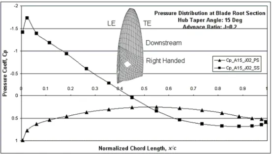
J=0.20 are shown in Figures 11 to 13 for hub taper angles of 0°, 15°, and -15° respectively. The pressure distribution of the propeller with zero hub angle at the blade root section, as shown in Figure 11, looks as expected: the majority of the blade thrust is produced by the leading edge and from negative pressure on the suction side. The pressure distribution for the propeller with a taper angle of 15° for the push configuration, as shown in Figure 12, shows some undesired crossover of the CP curves around mid-chord. The loop downstream of the crossover produced negative pressure difference, which leads to a reduction of total thrust produced by the blades. The crossover might result from the high pitch angle in combination with large sectional camber in the root section and hence a high hydrodynamic angle of attack.
The pressure distribution for the propeller with a taper angle of -15° in pull configuration, shown in Figure 13, shows much better pressure distribution. The area covered by the CP curves (thrust produced by that section) is now bigger than that of the straight-hub propeller, thus giving higher thrust. For the pull configuration, it is noted that the camber of the root section is substantially decreased due to intersection between the blade helical surface and cone surface, resulting a much smaller hydrodynamic angle of attack. Examining the pressure distribution, it is possible to design an optimized blade section and planform, based on the base propeller geometry, in terms of pitch and camber distribution for podded propellers of various configurations.
Figure 11. Numerical results showing the pressure distribution at blade root section of the model propeller in regular form (hub angle, A=0°; advance coefficient, J=0.2; PS=pressure side;
Figure 12. Numerical results showing the pressure distribution at blade root section of the model propeller for hub taper angle of 15o (hub angle, A=15°; advance coefficient, J=0.2; PS=pressure
side; SS=suction side).
Figure 13. Numerical results showing the pressure distribution at blade root section of the model propeller for hub taper angle of -15o (hub angle, A=-15°; advance coefficient, J=0.2; PS=pressure
side; SS=suction side). 3.4 Effect of pod-strut geometry (push configuration)
The effect of pod geometry on propeller performance was studied by calculating the propulsive characteristics of the two pods attached to the propeller in push configuration. The dimensions of the pods are given in Table 2. The predictions on thrust and torque of the propeller with and without the two pods are presented in terms of KT and KQ in Figures 14 and 15 respectively. It is clear from both figures that the thrust and torque of the pusher type pod configuration increase noticeably compared to the open propeller performance. The calculation estimates the effects of the potential wake of the pod-strut on the propeller and of the proximity of the pod-strut panels to the blades of
the propeller. No account is taken of the frictional wake from the pod-strut. A part of the estimated increase in thrust and torque of the propeller is due to this potential wake leading to an effective reduction in advance velocity of the propeller.
Quantitatively, in the bollard pull condition (advance coefficient, J=0) when pod #1 was
attached to the propeller in push configuration, an increase of around 41% in thrust coefficient and 45% in torque coefficient, as compared to that of the propeller in open water condition, were predicted. Again for pod #2 in push configuration, a increases of around 32% in thrust coefficient and 33% in torque coefficient in the design load condition were predicted. The presence of the pod-strut geometry forward of the propeller acts as a blockage similar to an ice blockage forward of a propeller. In an earlier study [18] it was measured as well as predicted that the thrust coefficient and torque coefficient were almost doubled due to the presence of an ice block (at a proximity of 1% radius of the propeller) forward of the propeller operating at an advance coefficient of J =0.4.
However, it must be remembered that in estimating the total thrust of the pod unit, this increase in thrust of the propeller will not lead to an equivalent increase in pod unit due to the thrust deduction effect between the propeller and the pod-strut and the drag of the pod-strut itself.
Figure 14. Numerical results showing the pod-strut geometry on the propulsive performance of the propeller for average pod #1 in push configuration. Here H15 means hub taper angle of 15°
Figure 15. Numerical results showing the pod-strut geometry on the propulsive performance of the propeller for average pod #2 in push configuration.
4 Concluding Remarks
An existing panel method code, PROPELLA, was extended to model hub taper angle and pod-strut configurations. Comparisons of the predicted performance with experimental measurements indicated that the predictions for the thrust coefficient, torque coefficient, and open water propulsive efficiency of the model propellers showed relatively good agreement with the experimental measurements in push configuration from the bollard pull conditions to the design load conditions.
Hub taper angle has influence on the propulsive performance of a marine screw propeller. The influence is more noticeable for highly loaded conditions than for lightly loaded conditions. In the bollard pull condition, an increase of approximately 4.7% in thrust coefficient and 5.2% in torque coefficient were predicted for the pull configuration compared to the push configuration with hub taper angle of +15° and –15°. These increases in thrust and torque should be considered while designing propellers for different pod configurations.
Mean pressure distributions around the blade root section for the propeller in regular form, push configuration and pull configuration were presented. The pressure distribution around the blade root section for the propeller in pull configuration differs a lot from that of the propeller in push configuration. Predictions suggested that for design purposes, these two propeller configurations should be considered separately to adjust blade root pitch and section camber in accordance with their required performance. Further experimental work on this matter is desired for validation.
Acknowledgements
The authors would like to express their gratitude to the Natural Sciences and Engineering Research Council (NSERC), the National Research Council (NRC), Memorial University, Oceanic Consulting Corp., and Thordon Bearings Inc. for their financial and other support. Thanks are also extended to the staff at the Institute for Ocean Technology, NRC for their assistance.
References
1. Facinelli W A, Muggeridge D, (1998), “Integrated System Analysis and Design of Podded Ship Propulsors.”, Marine Technology, Vol. 35, No. 3, July 1998, pp 151-174
2. Mewis F, (2001), “The Efficiency of Pod Propulsion”, 22nd Intl. Conf., HADMAR 2001, Narna, Bulgaria, 12 p.
3. Rains DA, Vanlandingham DJ, (1981), “Hydrodynamics of Podded Ship Propulsion”, Journal of Hydronautics, Vol 14, pp 18-24.
4. Karafiath G, Lyons D, (1999), “Pod Propulsion Hydrodynamics-U.S. Navy Experience”, Proc. FAST’99, pp 119-135.
5. Terwisga TV, Quadvlieg F and Valkhof H,(2001),“Steerable Propulsion Units: Hydrodynamic Issues and Design Consequences”, paper written on the occasion of the 80th anniversary of
Schottel GmbH & Co., 15 p.
6. Kurimo R, (1998),“Sea Trial Experience of the First Passenger Cruiser with Podded Propulsors”, Practical Design of Ships and Mobile Units, Elsevier Science B. V. pp 743-748.
7. Toxopeus S, Leoff G, (2002), “Manoeuvring Aspects of Fast Ships with Pods” 3rd Intl. EuroConf
on High-Performance Marine Vehicles, HIPER’02, Sept 2002, Bergen, pp 392-406.
8. Chen Benjamin YH, Tseng Carol L, (1995), “A Contra-Rotating Propeller Design for a High Speed Patrol Boat with Pod Propulsion”, Proc. FAST’95, pp 1003-1013.
9. Liu P, Bose N, (1998), “An Unsteady Panel Method for Highly Skewed Propellers in Non-Uniform Inflow”, Proc. of 22n ITTC Propulsion Committee: Propeller RANS/Panel Method Workshop, Grenoble, France, April, pp 343-350.
10. Liu P, Bose N and Colbourne B, (2001), “Automated Marine Propeller Geometry Generation of Arbitrary Configurations and a Wake Model for Far Field Momentum Prediction” Intl Shipbuilding Progress, Vol 48, no. 4, pp 351-381.
11. Liu P, (2002), “Design and Implementation for 3D Unsteady CFD Data Visualization with Object-Oriented MFC with OpenGL”, Computational Fluid Dynamics Journal, Vol 11, no. 3, pp 335-345.
12. Jessup SD, (1989), “An Experimental Investigation of Viscous Aspects of Propeller Blade Flow”, Ph.D. Thesis, School of Eng. and Arch., Catholic University, Washington D. C., U.S.A. 249 p.
13. Molly S, (2002), “Podded Propulsion: Systematic series and geometric variation ”, Proposal for PhD. Research, Memorial University of Newfoundland, Canada.
14. ITTC Quality Manual – Recommended Procedures, (2002), “Propulsion, Performance - Podded Propeller Tests and Extrapolation”, 7.5-02-03-01.3, Revision 00.
15. ITTC Quality Manual – Recommended Procedures, (2002), “Propulsion, Propulsor Uncertainty Analysis, Example for Open Water Test”, 7.5-02-03-02.2, Revision 00.
16. Bose N, Luznik, L, (1996), “Uncertainty Analysis in Propeller Open Water Tests”, Intl Shipbuilding Progress, Vol. 43, no. 435, pp. 237-246.
17. Coleman, H W, Steele, W G, (1989), “Experimentation and Uncertainty Analysis for Engineers”, Wiley Interscience.
18. Veitch B, Bose N, Meade C, Liu P, (1997), “Predictions of Hydrodynamic and Ice Contact Loads on Ice-Class Screw Propellers ”, Proc. of the 14th Intl. Conf. of Offshore Mechanics and Arctic Engr, Yokohama, Arctic, April 1997, pp 13-18.