READ THESE TERMS AND CONDITIONS CAREFULLY BEFORE USING THIS WEBSITE. https://nrc-publications.canada.ca/eng/copyright
Vous avez des questions? Nous pouvons vous aider. Pour communiquer directement avec un auteur, consultez la première page de la revue dans laquelle son article a été publié afin de trouver ses coordonnées. Si vous n’arrivez pas à les repérer, communiquez avec nous à [email protected].
Questions? Contact the NRC Publications Archive team at
[email protected]. If you wish to email the authors directly, please see the first page of the publication for their contact information.
NRC Publications Archive
Archives des publications du CNRC
This publication could be one of several versions: author’s original, accepted manuscript or the publisher’s version. / La version de cette publication peut être l’une des suivantes : la version prépublication de l’auteur, la version acceptée du manuscrit ou la version de l’éditeur.
Access and use of this website and the material on it are subject to the Terms and Conditions set forth at
Real-Time Geometrical Tracking and Pose Estimation Using Laser
Triangulation and Photogrammetry
Blais, François; Beraldin, Jean-Angelo; El-Hakim, Sabry; Cournoyer, Luc
https://publications-cnrc.canada.ca/fra/droits
L’accès à ce site Web et l’utilisation de son contenu sont assujettis aux conditions présentées dans le site
LISEZ CES CONDITIONS ATTENTIVEMENT AVANT D’UTILISER CE SITE WEB.
NRC Publications Record / Notice d'Archives des publications de CNRC:
https://nrc-publications.canada.ca/eng/view/object/?id=ded0c070-a02c-4768-83ce-a31b145b63c0 https://publications-cnrc.canada.ca/fra/voir/objet/?id=ded0c070-a02c-4768-83ce-a31b145b63c0National Research Council Canada Institute for Information Technology Conseil national de recherches Canada Institut de technologie de l'information
Real-Time Geometrical Tracking and Pose
Estimation Using Laser Triangulation and
Photogrammetry *
Blais, F., Beraldin, J.-A., El-Hakim, S.F., Cournoyer, L.
May 2001
* published in the Proceedings of the Third International Conference on 3D Digital Imaging and Modeling (3DIM). Québec, Québec, Canada. May 28 - June 1, 2001. NRC 44180.
Copyright 2001 by
National Research Council of Canada
Permission is granted to quote short excerpts and to reproduce figures and tables from this report, provided that the source of such material is fully acknowledged.
Real-time Geometrical Tracking and Pose Estimation using Laser Triangulation
and Photogrammetry
*F. Blais, J.-A.Beraldin, S. F. El-Hakim, L. Cournoyer
National Research Council of Canada
Institute for Information Technology
Ottawa, Ontario, Canada, K1A-0R6
Email:
[email protected]
*
NRC-44180
Abstract
Geometrical tracking and pose estimation using the homogeneous UVW inverse spherical coordinate system, directly from range data obtained from a triangulation based range sensor, are demonstrated. The method is shown to be more accurate, reliable, and computationally faster than using the more conventional XYZ Cartesian coordinate system. This is presented through a practical application, by comparing the accuracy and resolution of a 3D laser scanner prototype that geometrically tracks and computes the relative pose of objects in 3D space. The system uses real-time geometrical surface fitting and intensity processing for the detection and tracking of planar targets on an object. A dual-axis laser scanner is used for this demonstration that combines optical triangulation, Lissajous scanning patterns, geometrical tracking, and photogrammetry (spatial resection), to calculate the relative pose of objects in the 3D space.
1. Introduction – the application
Vision systems are key elements for several industrial and scientific applications. For space and in particular for the assembly and maintenance of the new International Space Station, vision is particularly crucial [1]. Unfortunately, space is also a harsh and challenging environment for vision based automation. The presence of the sun or any other strong sources of light will adversely affect the quality of video images and consequently the overall system accuracy and reliability. Poor contrast between features on the object and background makes the images distorted and often impossible to analyse. Even under supervised operation and careful planning, the wide dynamic range of illumination in orbit is a challenging problem for any optical sensing device. Other environmental conditions like vacuum and temperature swings have also their own impact on the equipment performance and stability.
Conventional video and still cameras are attractive because of their ease of use, low maintenance, and simplicity of integration to existing equipment. However they also have serious limitations that will affect the overall system accuracy. As an example, the quality of the image of Figure 1, although visually excellent is problematic for automated operation because of lost of details in the object structure, saturation, interference by the moving earth background, and shadows created by the sun or the shuttle.
A very important and fundamental question for vision systems is how the whole physical acquisition process operates and not only the imaging device or the processing algorithms tested under ideal conditions. Although there is a desire for a single imaging system to perform all functions, this is still far from being possible [2]. Considering that the laws of physics can’t be broken,
Figure 1. The existing Space Vision System (SVS) uses the known locations of the B/W targets to compute the pose of objects. Effects of sun illumination and earth albedo on video images that affect accuracy and reliability are wide dynamic range, poor signal, saturation, and shadows. (Courtesy NASA).
what is the maximum accuracy obtainable with a given system? For example, even in the presence of a perfect optical system, diffraction is a lower limit; resolution is given by the Airy disk radius rather than by the number of pixels on the CCD.
The shuttle Space Vision System [3] uses Inconel targets on sections of the International Space Station to compute the pose (6 DOF) of the different modules for part alignment during assembly. Sub-pixel target centroids are feed to the photogrammetry based photo-solution algorithm to obtain the pose of the object [4]. Inconel targets are used rather than the natural features of the object to increase system accuracy. Accuracies of 1 cm in translation and 0.1 deg in rotation at a distance of 10-15 m are obtained, a requirement from NASA. Since sub-pixel centroid detection is needed for accurate measurement, any missing and/or light distorted targets or object features will adversely affect the performances of any photogrammetric and/or stereoscopic based vision systems.
It is therefore very important that any complementary technology like a laser scanner be robust to operational conditions such as sun interference, saturation, shadows, or simply insufficient light. Table 1 shows typical conditions observed during operation in orbit.
Table 1. Conditions for ambient illumination and their effects on the Laser Scanner System.
Illumination
conditions
Possible effect on laser
scanner
Normal conditions None – normal conditions
Target shadowing Slightly reduced accuracy–
signal intensity distortion or small local saturation
Saturation (Field of view)
Minimal – normally outside instantaneous FOV of laser scanner
No Light (Dark) None - Ideal for laser scanner
Furthermore, since the laser scanner provides range data, geometrical processing and tracking algorithms become key elements in making the whole system robust. The inhomogeous and anisotropic behavior of the measurement error distributions of a triangulation based laser scanners, although known, is still poorly understood and often neglected. Basically, the measurement uncertainty of triangulation-based systems is inversely proportional to the inverse of range squared and the accuracy is highly affected by the pointing origin of the deflection system (or by analogy, the lens principal point in the case of a video camera based sensors). There are advantages of using the homogeneous UVW spherical
coordinate system for both geometrical target processing and pose estimation. These are covered in this paper.
Since the whole system is important, and not only the specifics of the processing algorithms, we will present the proposed method in a rather general format. Section 2 will quickly introduce the laser scanner solution and some of the control aspects developed for this project. Sections 3 and 4 will cover the acquisition geometry and target tracking method. One of the important feature of the proposed method is to combine in a single unit different ranging and object pose estimation techniques. Section 6 will concentrate on two 3D-pose estimation methods:
• using triangulation and the calibrated XYZ
coordinates of the targets,
• spatial resection compatible with the current
Space Vision System (SVS).
Finally, experimental results are presented in section 7 along with concluding remarks in Section 8.
2. The laser tracking system
The range laser scanner approach offers the potential of being 100% operational throughout the ever-changing illumination conditions in orbit. The laser tracker used for this demonstration is shown in Figure 2. It has two high-speed galvanometers and a collimated laser beam to address individual points on an object. High-resolution images and excellent tracking accuracy are obtained.
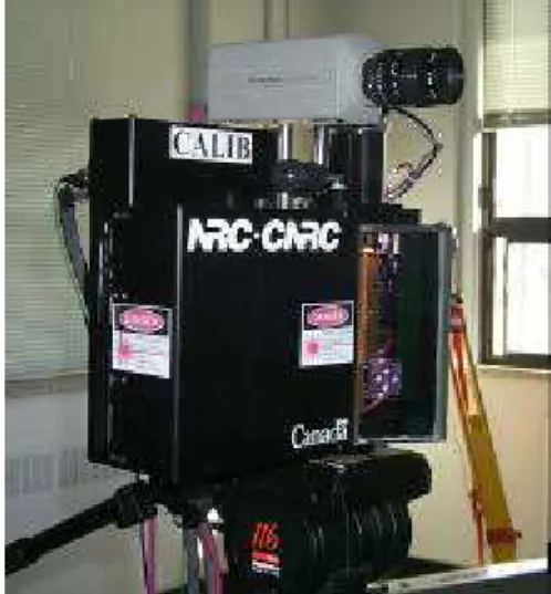
Figure 2. Prototype of the laser scanner system, a conventional video camera is “temporarily” mounted on the laser scanner for monitoring and comparison with conventional video methods.
The electro-optical performances of the auto-synchronized laser scanner used in this paper and the
analysis of system sensitivity to sun interferences have been presented in previous publications [5-6]. Details of the laser scanner operations and its integration to the SVS system for tracking operation appear in reference [7].
The laser scanner optics is diffraction limited and the image of the laser spot on the CCD is always in focus for the whole operating volume. The combined advantages of small instantaneous FOV, optical interference filters, and dedicated signal processing minimizes the effect of sun interferences on the video signal [6].
Real-time tracking of geometrical targets is shown in Figure 3 using Lissajous figures. In this paper a target is defined as either geometrical and/or intensity features on an object. The tracker addresses sequentially individual targets on the object as shown in Figure 4. Very high resolution and excellent pointing accuracy are obtained,
40 ìrad for a FOV of 40 deg × 30 deg [5,7,8]. This is
equivalent to a 14000 × 10000 elements CCD imager.
Dimensions of the scanner are 27 cm × 18 cm × 10 cm.
Different laser wavelengths have been tested, from eye-safe wavelength of 1.5 µm with, infrared at 820 nm, and green at 532 nm, with minor modifications to the electro-optics, interference filters, and coatings of the mirrors, lens and windows.
In [7] and in Figure 4, tracking of retro-reflective targets was used to demonstrate the operation of the laser scanner. The system can now geometrically track Black on White, White on Black, and simple geometries, as well as retro-reflective targets as shown in Figure 3. For NASA, tracking compatibility with existing black Inconel targets was imperative for this application. In [8] we have analyzed the optical characteristics of the laser scanner system and demonstrated the effectiveness of the solution to sun interference.
3. Range measurement and geometrical
target processing
Using triangulation, the laser scanner system can measure range information (x,y,z) for each voxel (3D volumetric element) in its field of view [9]. Here, we will use the simplified model illustrated in Figure 5 to model range measurements using triangulation and to associate geometrical tracking and object pose estimation. We will use the error model as the basis to demonstrate the purpose of using the scanner coordinate system UVW for geometrical tracking and pose estimation.
Figure 3. Tracking using the Lissajous pattern and a planar circular target (left) or a geometrical target (right) of similar color as the background.
Figure 4. Real-time tracking of targets on the simulated Node and Z1 modules, two types of target are visible, Inconel B/W and retro-reflective targets. The system tracks each target sequentially. In this example, one of the targets is in “search mode” (larger Lissajous pattern).
Figure 5. Simplified geometrical model of the laser scanner showing the effect of astigmatism between the x and y scanning axes (see [8] for details). Rotation X-Axis Rotation Y-Axis X Z Y CCD Lens Dg (0,0,0) φ θ R
From [9] and from Figure 5, assuming a simplified aberration-free model, a vergence reduced to 0 (both laser and optical axis point to infinity) and setting R=z/cos(θ), range R can be calculated as:
) sin( ) cos(θ d θ p d f R = ⋅ + (1)
where f is the focal length of the imaging lens, d is the triangulation base, θ is the deflection angle parallel to the x-axis, and p is the position of the imaged laser spot of the position sensor [6,9]. The x-y-z coordinates of a point are
(
)
+ − − ⋅ = ) cos( ) cos( )) cos( 1 ( ) sin( ) cos( ) sin( φ θ ψ φ φ ψ θ θ R z y x (2)where θ and φ are the deflection angles, and ψ=Dg/R
where Dg is the separation between the two scanning mirrors (or axis). Full model calibration is given in [9] but since we are here mostly interested with measurement uncertainty, the error analysis from equation 2 is more than sufficient.
Because Dg<<R, error propagation calculations (in triangulation mode) can be approximated by
p d f R RTrian ∆ ⋅ ≈ ∆ 2 (3)
Obviously the system astigmatism created by Dg, and the overall system distortions are not negligible and will introduce bias in the measurements for pose estimation. However for random noise analysis and geometrical tracking equation 3 is still a very good approximation. The total errors across the field of view of the laser scanner become:
φ
θ
φ
φ
θ
φ
θ
φ
θ
θ
φ
θ
φ
θ
θ
∆
⋅
⋅
−
+
∆
⋅
−
⋅
−
+
∆
⋅
⋅
⋅
=
∆
∆
∆
)
(
cos
)
sin(
)
cos(
0
)
cos(
)
sin(
)
sin(
)
sin(
)
cos(
)
cos(
)
cos(
)
sin(
)
cos(
)
sin(
2R
R
p
d
f
R
z
y
x
(4)where ∆p is the laser spot position uncertainty limited mostly by the laser speckle, notice the R2 dependence of the error. For medium to long range, the total system
error, for each x-y-z coordinate, is mostly contributed by range error measurement ∆R, i.e., ∆p the uncertainty
associated with the laser spot measurement [6,9].
4. Real-time tracking – Lissajous patterns
Real-time tracking of targets or geometrical features on an object is implemented using Lissajous patterns [5] by driving the two axis galvanometers with sine waves of different frequencies (Figure 3). Lissajous patterns are used to efficiently scan objects at refresh rates exceeding the bandwidth of the mechanical deflection system. Tracking speed several orders of magnitude faster than using the more conventional raster imaging, is obtained. As an example at a sampling frequency of 15 kHz, a 128
× 128 raster image will take a little over 1 sec per target while a 256 points Lissajous pattern will take only 17 msec. Furthermore, the Lissajous tracking pattern is a key feature to increase angular accuracy by using the natural inertia of the deflection system to average out pointing noise.
Figure 4 shows the multiple targets tracking process. The tracking system is programmed to sequentially scan different sections of the object. Errors introduced by the measurement are always minimized because the scanner automatically centers and optimizes the size of the tracking patterns based on the measured target to object distance, for each target individually. Furthermore, the laser spot position sensor sensitivity and laser power are optimized on a per target basis.
The geometrical tracking principle uses both the 3D range and intensity information on the Lissajous pattern to (a) identify targets on the object or any useful geometrical feature, and (b) to discriminate the target from its background (Figure 3). Although it seems a-priori that intensity reflectance should be sufficient to locate the targets, in practice this is far from reality since target reflectivity is highly dependant on surface material, angle of incidence on the surface, specular reflections, and ambient illumination. B/W (or intensity) targets/feature tracking brings very interesting and practical challenges for automated target detection:
• target illumination and poor contrast between the
targets and their surrounding background,
• specular reflections created by metallic structures
• defects and non-uniformity of the target surfaces,
• variations in the material reflectivity between targets (retro, B/W, W/B), target incident angles,
• ambient intensity variations and shadows introduced
by the Sun,
At a wavelength of 820 nm or at 1.5 µm, the signal ratio between the white target and its darker background varies between 2:1 and 1.5:1 depending on the incident angle of the laser beam (10:1 for Inconel material). Other interesting dynamic signal ratios are non-uniform signal response of the “dark” background and vignetting (3:1), variations of reflectivity versus surface incident angle (4:1), specularity of non-diffusing surfaces (>20:1), ambient light and shadows (3:1), variation of target reflectivity with range (>100:1). The system must therefore exhibit equivalent SNR of more than 104 to 105 of dynamic range, far exceeding the 256:1 ratio of conventional frame grabbers and the 20:1 of electronic shutters. This is accomplished here by dynamically varying the laser power and the sensitivity of the laser spot position sensor on a per target basis, and by automatic compensation of the non-linear dynamics of the scanning system.
Figure 6. Experimental setup used to verify the accuracy of the tracking system. The blinds were shut to prevent saturation in this photograph.
Figure 7: Effect of light shadows on a target.
5. Real-time geometrical tracking
Because of the constraints of signal dynamic range (104 to 105 and Figure 7) geometrical range processing is the only reliable method to differentiate the target from its
environment. To simplify the discussion, we are assuming that most geometrical objects can be modeled using planar surfaces (or meshes). The equation of a plane is
c y b x a z= ⋅ + ⋅ + (4) However there is major drawback using quadratic error plane fitting in the XYZ coordinate system because x, y, and z are highly correlated with range R (equation 4). The use of the normal form 0=ax+by+cz+d is not better.
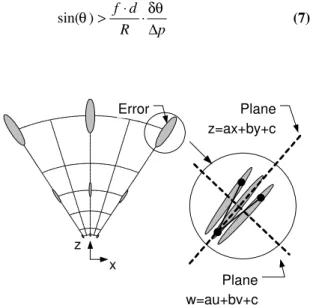
Referring to Figure 8, the distribution of the errors in the x-z plane is depicted with ellipses with varying dimensions in order to show the anisotropy and inhomogeneity of the distribution. Statistically, this will show as non-zero terms outside the diagonal of the error covariance matrix. Physically, this will be seen as non-continuous profiles as illustrated in Figure 8 where we have retrograde motion in the x profile. Assuming a small angular scanning increment δθ (different than the error
∆θ) then from equation (4)
(6)
Even if the scanning is very uniform, retrograde motion (∆x<0) along the x profile will be introduced as shown in Figure 8 (and for y). This lost of profile continuity is seen for scanning angles θ that meet the condition p R d f ∆ ⋅ ⋅ > δθ θ) sin( (7) z x Error Plane z=ax+by+c Plane w=au+bv+c
Figure 8. Dependencies of x-y-z measurement errors with radial range R (equation 4). Note the retrograde motion of the x-axis and the plane fits. δθ θ θ ⋅∆ + ⋅ ⋅ ⋅ ⋅ = ∆ p R d f R x sin( ) cos( ) 2
Using the UVW coordinate system, from Equation 1 and assuming ψ=0
(8)
equation (5) becomes
(9)
and correlation between the new coordinates u,v,w is minimized as opposed to the XYZ coordinate system.
Of primary interest is the direct relationship between the raw measurements and the equation of a plane as illustrated in Figure 8. Linear minimization techniques can then be efficiently used since the errors are constant for the whole volume. Furthermore, because u and v are
mostly correlated with only the angles ϕ and θ, the
quadratic error minimization of equation 9 will not be ill-conditioned, of primary importance for real-time computation.
To further increase speed, assuming a change of coordinates θ′=θ−θo, and ϕ′=ϕ−ϕo and small sustained
angles, equation 8 can be approximated using
(10)
Only model-based calibration of the centroid of the target and/or the coefficients of the fit are needed for accurate pose estimation.
It is important to note that the inverse spherical coordinate system described here will be even better adapted to more conventional triangulation based plane of light sensors and/or the Biris method.
Several techniques can be used for plane extraction; the method we selected combines split and merge and outlier removal (robust fitting). And to further differentiate the B/W circular target itself from its immediate background, the intensity contrast was used locally. Although the best circle projected on the previously measured plane is ideal, we found that the centroid measurement was more than adequate because of the relative small size of the targets used in this
demonstration. The w coordinate is obtained from the centroid u,v and equation 9.
Obviously the method can also be easily extended to any surfaces, corners, cube (intersections of surfaces).
6. Object pose evaluation
Object pose evaluation is a complex subject by itself and an in depth analysis is beyond the scope of this paper. We will rather provide here a qualitative analysis of the method from an empirical point of view based on similar concepts.
Assuming a set of known coordinates (xo,yo,zo) on a
rigid object, the expected location of these targets in the laser scanner 3D space (x),y),z)) is given using:
(11)
where M is a 4x4 rigid transformation matrix (|M|=1) that maps the object target coordinates Xo=
[
xo yo zo 1]
Tinthe laser scanner space Xˆ =
[
xˆ yˆ zˆ 1]
T. The matrixM has 6 unknowns, 3 translations and 3 rotations
(yaw-pitch-roll). Object pose estimation consists of evaluating the transformation matrix that will minimize a set of error equations. The most commonly used method minimize the quadratic error between the expected position computed from the previous equation and the laser
scanner measurements X=
[
x y z 1]
T:(12)
(13) Different techniques are available to minimize this set of equations such as based on least-squares adjustment, and quaternions. For medium to long range and from equation 4 , we can see that the error vector E will be highly dependent on the range measurement R,
(14)
Using the camera pinhole model of equation 8, and photogrammetry methods, pose estimation requires the minimization of the error vector
(15)
of the projected vector U=[u v 1]T. From equations 8 and 10, the dependence of the error vector E on range R is minimized. Accuracy of the photogrammetric method
o X M Xˆ = ⋅ ) min(
∑
ÅT⋅Å X X Å= − ˆ p R ∆ ≈ ∆E 2 = = ) cos( ) cos( 1 ) tan( ) cos( ) tan( 1 θ φ φ φ θ R z z y z x w v u U U Å= − ˆ v c b u c a c w=1− − ⋅ = = d f p z z y z x w v u ' ' 1 φ θshould then be much better than direct range data minimization for medium to long range R. The use of the vector W=[u v w 1]T is also another possible method, we have not tested it yet.
Figure 11 illustrates the two object pose evaluation concepts. Obviously, to obtain the desired pose accuracy, the data must first be calibrated using the complete laser scanner model. However since we are only calibrating the location of the centroid of the target, real-time constraints are much reduced.
U V Scanner Scanner R dx dy X Y Z
Figure 11: Object pose calculation based on photogrammetry techniques (left) and 3D range data (right).
7. Experimental results
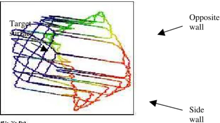
Lissajous scanning pattern data are more difficult to visualize since they do not correspond to the more “conventional” raster image and because of the small point density. Figure 12 shows a 3D geometrical profile of a target plane using 6:5 Lissajous pattern. The Black on White target in the lower right corner of Figure 7 was acquired. Visible are the target surface and the two corner walls.
Figure 12: Lissajous profile of the B/W target of Fig. 7 (bottom right target) using a 6:5 Lissajous pattern.
Figure 13: Model simulation and experimental results for analysis of the stability of the pose.
In order to compare the two pose estimation methods, the targets on the structure shown in Figure 7 were divided in three groups and the targets acquired over a period of twelve hours. Standard deviation of the pointing stability for the targets was 40 µrad as opposed to 150
µrad in [8]. Figure 13 shows the results of the object pose model (simulation) using the previous methods for a 1 m
× 1 m array and for the targets of Figure 7. Increased stability/resolution using the photogrammetric model UV, compared to XYZ data is important. At the time of writing, work for the calibration of the laser scanner is still in progress and the absolute accuracy experimental results of the method were not available.
There are several key factors that must be considered when comparing the stability of the pose from the model data and these experimental results, the most important being the distribution and angular size of the targets. For the UVW method, the distribution of the targets on the structures of Figure 7 is definitely an advantage, providing a large triangulation base (Figure 11). The model uses a regular target array of 1 m × 1 m, while the experimental data uses targets distributed within the whole FOV of the laser scanner. This gain is more important at longer range for the UV method and almost negligible for the XYZ method. Size of the target and pointing accuracy are also important when compared to preliminary results obtained in [8].
From both the simulated model and experimental data, an increased in accuracy using resection is obvious. This clearly demonstrates the advantages of the combined methods, i.e. the use of a laser range scanner as a projective camera. Target surface Opposite wall Side wall 0.1 1 10 100 0 5 10 15 20 Range (m) Z St ability Error (mm)
XYZ - Simulation XYZ - Experimental
8. Conclusion
Real-time geometrical target processing and tracking in the laser scanner inverse spherical coordinate system has been presented. Using the homogenous UVW coordinates system, the high correlation normally obtained using the three axes x-y-z axis in the Cartesian coordinate system relative to the object distance R was minimized. The UVW coordinate system also eliminated the z2 dependency of range error, linearizing the error equations, and more important, eliminating the possibility of ill-conditioned systems of equations.
Based on the high-resolution pointing measurement and range information for each individual target, the estimation of the 3D poses of objects was also computed. Combining the ranging with the high pointing accuracy obtained using the Lissajous tracking pattern and photogrammetric methods (spatial resection), increased accuracy in the pose estimation of the object by approximately an order of magnitude was obtained. This compares advantageously to the more conventional methods using the XYZ Cartesian coordinate system. To demonstrate the validity of the approach and to demonstrate high immunity to ambient illumination and sun interference, a 3D laser tracking system was used. Excellent geometrical tracking characteristics and pose measurement were experimentally obtained. Three types of targets have been tracked in real real-time using Lissajous scanning patterns: 1) Retro-reflective targets, 2) White on Black background, and 3) planar Black on White background, and 4) simple 3D geometrical targets. This combination makes the laser scanner compatible with the current Space Vision System (SVS) used by NASA.
Both geometrical and pose estimation techniques using the UVW coordinate system have also demonstrated that minimizing the error associated with the measurements (UVW) is much more efficient than minimizing the errors associated with the measurands XYZ.
9. Acknowledgments
This work is part of a more ambitious collaborative project between Neptec Design Group, the NRC and CSA, of developing flying a space qualified version of this laser scanner system. The authors would like to acknowledge their precious collaboration. Thanks also to PRECARN for funding parts of this effort and to Michel Picard for his technical support
10. References
1. S.G. MacLean, and H.F.L. Pinkney., “Machine Vision in Space,” Canadian Aeronautics and Space Journal, 39(2), 63-77 (1993).
2. G.C. Holst, “Electro-Optical Imaging System Performance,” SPIE Optical Engineering Press, JCD Publishing, Winter Park, FL., 1995.
3. http://www.neptec.com
4. S.G. MacLean, M. Rioux, F. Blais, J. Grodski, P. Milgram, H.F.L. Pinkney, and B.A. Aikenhead,., “Vision System Development in a Space Simulation Laboratory,”in Close-Range Photogrammetry Meets Machine Vision, Proc. Soc. Photo-Opt. Instrum. Eng., 1394, 8-15 (1990).
5. F. Blais, & al., “Development of a Real-time Tracking Laser Range Scanner for Space Application,” Proceedings Workshop on Computer Vision for Space Applications, Antibes, France, September 22-24, 161-171 (1993).
6. Beraldin, J.-A., Blais, F., Rioux, M., Cournoyer, L., Laurin, D., and MacLean, S.G., “Eye-safe digital 3D sensing for space applications”. Opt. Eng. 39(1): 196-211; Jan. 2000.
7. F.Blais, J.-A. Beraldin, L.Cournoyer, I. Christie, R. Serafini, K. Mason, S. McCarthy, C. Goodall., “Integration of a Tracking Laser Range Camera with the Photogrammetry based Space Vision System”, Acquisition, Tracking, and Pointing XIV, Proceedings of SPIE’s Aerosense 2000 Vol. 4025, p. 219-228, (2000), Orlando, FL.
8. F. Blais, J.-A. Beraldin, S. El-Hakim., “Range Error Analysis of an Integrated Time-of-Flight, Triangulation, and Photogrammetric 3D Laser Scanning System,” Laser Radar Technology and Applications V, Proceedings of SPIE’s Aerosense 2000 Vol. 4035, p. 236-247, (2000), Orlando, FL. 9. J.-A. Beraldin, S.F. El-Hakim, and L. Cournoyer.,
“Practical Range Camera Calibration,” Proc. Soc. Photo-Opt. Instrum. Eng. 2067, 21-31 (1993).