HAL Id: hal-03133218
https://hal.archives-ouvertes.fr/hal-03133218
Submitted on 8 Feb 2021HAL is a multi-disciplinary open access archive for the deposit and dissemination of sci-entific research documents, whether they are pub-lished or not. The documents may come from teaching and research institutions in France or abroad, or from public or private research centers.
L’archive ouverte pluridisciplinaire HAL, est destinée au dépôt et à la diffusion de documents scientifiques de niveau recherche, publiés ou non, émanant des établissements d’enseignement et de recherche français ou étrangers, des laboratoires publics ou privés.
Interfacial microstructure of graphite flake reinforced
aluminum matrix composites fabricated via hot pressing
Hiroki Kurita, Takamichi Miyazaki, Akira Kawasaki, Yongfeng Lu,
Jean-François Silvain
To cite this version:
Hiroki Kurita, Takamichi Miyazaki, Akira Kawasaki, Yongfeng Lu, Jean-François Silvain. Inter-facial microstructure of graphite flake reinforced aluminum matrix composites fabricated via hot pressing. Composites Part A: Applied Science and Manufacturing, Elsevier, 2015, 73, pp.125-131. �10.1016/j.compositesa.2015.03.013�. �hal-03133218�
Interfacial Microstructure of Graphite Flake Reinforced Aluminum Matrix Composites Fabricated via Hot Pressing
Hiroki Kurita1,4*, Takamichi Miyazaki2, Akira Kawasaki3, Yongfeng Lu5 and Jean-François Silvain4 1DEN/DANS/DMN/SRMA/LTMEx, CEA Saclay, France
2Technical Division, School of Engineering, Tohoku University, Japan
3Department of Materials Processing, Graduate School of Engineering, Tohoku University, Japan 4Institut de Chimie de la Matière Condensée de Bordeaux (ICMCB-CNRS), France
5Department of Electrical Engineering, University of Nebraska-Lincoln, 217N WSEC, Lincoln, Nebraska 68588-0511, USA
Corresponding author (H.Kurita):
* hiroki.kurita@live.com, phone: +33 1 69 08 34 28, fax: +33 1 69 08 82 52
Abstract
The microstructure of graphite flake (GF) reinforced aluminum (Al) matrix (Al–GF) composites was observed in detail. Due to thermal stress, a nano space was created within the GF in proximity to the Al/GF interface, while the unique bridging of the sticky graphite sheets barely connected the Al matrix and GF. This result suggests that the GF interlaminar strength is weaker than the Al/GF interfacial strength; the GF interlaminar strength is thus the dominant determinant of the thermomechanical and mechanical properties of the Al–GF composite. Whereas the thermal conductivity of the Al–GF composite was consistent with that theoretically predicted, the outstanding thermal expansion coefficient (TEC) of the graphite was not reflected in the produced Al–GF composites. The damaged inner structure of GF in proximity to the Al/GF interface contributes to heat transfer but does not bear the load resulting from thermal stress.
Exponential progress in the development of new electronic components requires the use of high-performance heat sink materials, which strike a balance between high thermal conductivity and a thermal expansion coefficient (TEC) close to that of semiconductors and ceramic substrates in order to minimize thermal stress at the joints.1 As potential heat sink materials, metal matrix composites have been studied owing to their tunable thermal properties. Due to their low density, Aluminum (Al)-based composites have a great advantage in terms of the fabrication of mobile electronic devices, which have become mainstream in recent years.2-5 Al-based composites are generally fabricated via solid-phase methods (e.g. powder metallurgy) in order to avoid excess interfacial reaction, although the aluminum oxide (Al2O3) layer which covers the surface of Al particles often interrupts densification in solid-phase processes.6-8
A range of materials have been considered for use as reinforcements in Al-based heat sink composite materials, including silicon carbide (SiC),2 aluminum nitride (AlN),3 and various carbon materials.4,9,10 Carbon materials such as diamond and carbon fiber are promising because of their outstanding thermal conductivity, while they are also reactive with Al. However, although diamond reportedly combines remarkable thermal conductivity (1000 ~ 2000 W/m・K) with a low CTE (2.1×10⁻⁶ /K),11 it is expensive and complicates secondary processing. In contrast, carbon fiber is inexpensive and has an advantage in terms of workability - although its thermal conductivity is lower than that of diamond. It has been reported that carbon fiber exhibits anisotropic thermal conductivity and TEC, with recorded values of ~ 1100 W/m・K and −1.45 ~ −0.6 ×10⁻⁶ /K in the longitudinal direction,12,13 and 5 W/m・K and 12.0×10⁻⁶ /K in the transverse direction.13
While the thermal and thermomechanical properties of actual graphite flakes (GFs) have not been widely reported, it is largely assumed that GF combines thermal and thermomechanical properties comparable to those of diamond (in the a-b plane) with a workability similar to that of carbon fiber, according to the reported thermal and thermomechanical properties of highly oriented graphite bulks.
Murakami et al. have revealed that the highly oriented graphite block obtained from polycondensation polymer films has a thermal conductivity higher than 1000 W/m・K and a TEC of −1.0×10⁻⁶ /K in the a-b plane.14 It has also been reported that highly oriented pyrolytic graphite (HOPG) has a thermal conductivity of 1600 ~ 2000 W/m・K and a TEC of −1.0×10⁻⁶ /K in the a-b plane.15,16 GF therefore appears to be a suitable material for the reinforcement of Al-base composites for use in thermal management applications. Indeed, Chen et al. have already documented the remarkable thermal conductivity and TEC of a graphite flake reinforced Al matrix (Al–GF) composite.17 However, studies involving the microstructural characterization of Al–GF composites are scarce, with the correlation between composite microstructure and thermal and thermomechanical properties not yet understood. In the present study a detailed observation is made of the microstructure of an Al–GF composite, especially at the Al/GF interface. The Al–GF composite was prepared via conventional hot pressing. As previous research has reported that a small quantity of aluminum-silicon alloy (Al-Si) effectively helps the densification process in Al-based composites,18 a small amount of Al-Si was introduced into the Al matrix powder. Furthermore, we also investigated the thermal conductivity and TEC of the fabricated Al–GF composite, discussing these properties in terms of composite microstructure.
2. Materials and methods
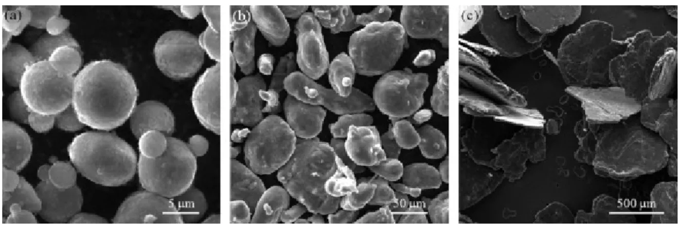
Spherical Al powder (F3731, Hermillon Powders, Fig.1a) with an average diameter of 8 μm, to which was added 5 vol% of Al-Si11.3at% alloy powder (Al-Si; F2071, Hermillon Powders, Fig.1b) with an average diameter of 100 μm, was prepared as a matrix powder. Graphite flakes (GF; Yanxin-Graphite Co.,Ltd., Fig.1c) at 32 mesh and an average thickness of 30 ~ 50 μm were prepared as a reinforcement, and mixed with the matrix powder for 5 minutes to obtain an Al + GF powder.
After compacting the Al + GF powder in a carbon mold, columnar Al–GF composite bulk (10 × 8 mm3) was fabricated by hot pressing for 30 minutes at 600 °C (between the melting points of Al-Si (584.6 °C) and Al (660 °C)) under a uniaxial compressive stress of 60 MPa. The volume fraction of
GF in the final Al–GF composite was controlled at 10, 30, and 50 vol%. The hot pressing temperature was monitored via a K-type thermocouple located 2 mm from the sample in the carbon mold. Here the fibers tend to be aligned in the in-plane direction due to the uniaxial compressive stress in the hot press.4,13 Therefore, a number of fabricated Al–GF columns were vertically machined to 6 × 4 mm3 in order to prepare the specimens for thermal conductivity and TEC investigations in the in-plane direction with graphite orientation.
The relative density of the Al–GF composites was measured using the Archimedes principle. Microstructural characterization of the Al–GF composite was carried out via scanning electron microscopy (SEM; Tescan, VEGA©) and high-resolution transmission electron microscopy (HR-TEM ; JEOL 2000-FX). For (HR-TEM observation, thin specimens of Al–GF 50 vol% composites were prepared using the ion milling system (GATAN PIPS Model 691), after mechanical polishing with waterproof abrasive silicon carbide papers (#600, #1200, #2000, #4000) to less than 50 μm thickness.
The thermal conductivity of the Al–GF composites (Kc) was estimated using the following equation:
p
c C
K ...(1)
where is the thermal diffusivity of the Al–GF composites, which was measured via the flash laser method (NETZSCH LFA 457, MicroFlash®) at room temperature. The thermal diffusivity of the Al– GF composites was measured parallel and perpendicular to the stress axis (i.e. the transverse and in-plane directions of the GFs). and Cp are the measured density and the heat capacity of the Al–GF composite, respectively. Cp was calculated from the heat capacities of graphite and pure Al by the rule of mixture.
The TEC of the Al–GF composites was measured perpendicular to the stress axis in the hot press (i.e. the in-plane direction of the graphite flakes), under an argon gas flow in two thermal cycles between room temperature and 250 °C with a heating/cooling rate of 2 °C/min, using a TEC measurement system (NETZSCH DIL 402, PC®). TEC values were estimated from the averages obtained in 2 thermal cycles between 100 and 180 °C.
3. Results and Discussion
3.1. Microstructure of the Al–GF composites
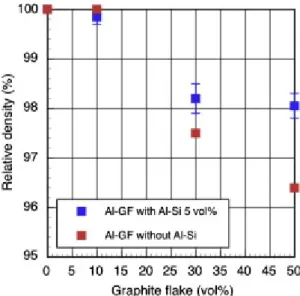
Figure 2 shows the relative densities of the Al–GF composites. The relative density of the Al–GF 10 vol% composites was 99 %, regardless of the addition of Al-Si. For composites with more than 30 vol% GF, the relative density remained higher than 98 % with Al-Si 5 vol%, but decreased without the addition of Al-Si. SEM observation revealed that GFs were effectively oriented in the in-plane direction due to the uniaxial compressive stress in the hot press (see Figs. 3a and 3c).4,13 Voids were mainly observed between the GFs and the Al matrix, with the number of voids greater in Al–GF composites fabricated without Al-Si than in those with Al-Si 5 vol%. This result is consistent with the relative density of the Al–GF composites. Without Al-Si, the Al/GF interface seemed intimate and rectilinear (see Fig. 3b), i.e. a similar microstructure to that reported by Chen et al.17 In contrast, with Al-Si 5 vol% the Al/GF interface was intricate, as shown in Fig. 3d. It seems that this intricate Al/GF interface is formed by the incorporation of detached graphite fragments into the Al particle boundaries around the Al/GF interface, a process which is thought to be furthered by the transformation of Al-Si to a liquid phase at the dwell temperature (600 °C) during the fabrication process.
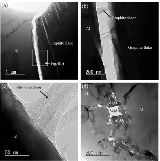
Figure 4 displays TEM micrographs of the Al–GF composite fabricated without Al-Si. Although the Al/GF interface initially seemed intimate in SEM micrographs (see Fig. 3b), TEM observation revealed the presence of a nano space along the interface (see Fig. 4a). For an Al–carbon fiber composite, we have previously reported that the Al/carbon fiber interface is intimate due to the compressive stress attributed to the larger TEC of the Al matrix than that in the transverse direction of the carbon fiber; the Al matrix shrinks more than the carbon fiber during the cooling process.4 In contrast, the TEC of graphite along the c-axis is larger than that of Al.14-16 Therefore, in the present case it seems that the greater shrinkage of GF than that of Al caused the tensile stress along the c-axis and thus created the nano space along the Al/GF interface during the cooling process, even if the Al/Graphite interface has no thermal stress and is intimately contacted at the dwell temperature
(600 °C). Further TEM observation revealed that the sticky graphite sheets bridged the Al matrix and GF, in the nano space (see Fig. 4b and 4c). This result implies that a few graphite layers still remain at the side of the Al matrix and the actual Al/GF interface is intimately contacted. Therefore, it seems that the nano space is created within the GF in proximity to the Al/GF interface, but not at the Al/GF interface itself. Furthermore, this result also indicates that the interlaminar strength of GF in proximity to the Al/GF interface is weaker than the Al/GF interfacial strength, along the GF c-axis. Although this bridging prohibits the complete independence of GFs from the Al matrix, it is inferred that the bridging does not represent strong mechanical bonding. In the Al matrix, a number of voids were observed between aluminum oxide (Al2O3) crystals (see Fig. 4d). Lalet et al. have previously reported that such crystals in Al matrix composites represent the oxide layer, which covers the surfaces of Al particles before hot pressing, i.e. the Al2O3 layer reveals the location of Al particle boundaries.19 Therefore, it seems that the observed voids were created at the Al particle boundaries. This result is consistent with the fabrication conditions of the Al–GF composite in the present study; Al does not infiltrate small spaces when the Al–GF composite is fabricated in a solid state, with the voids thus seemingly inhibiting the densification of the Al–GF composite.
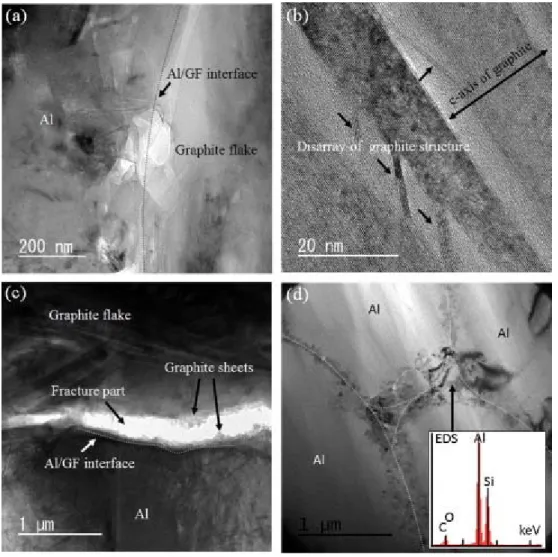
Figure 5 displays TEM micrographs of the Al–GF composite fabricated with 5 vol% Al-Si. As this figure shows, the Al/GF interface is largely intimate with no visible Al4C3 (see Fig. 5a). While the incorporation of graphite fragments into the Al matrix made the Al/GF interface indistinct, it also prevented the creation of nano space via the thermal stress resulting from the difference in TEC values between Al matrix and GF. However, the inner structure of the GF in proximity to the Al/GF interface was observed as being in disarray (see Fig. 5b), likely caused by the non-release of thermal stress due to the prevention of nano space creation. In terms of the damage caused to the inner structure of GF in proximity to the Al/GF interface, it seems that the aforementioned disarray is essentially no different from the bridging of graphite sheets between Al matrix and GF, i.e. it indicates that the interlaminar strength of GF along the c-axis (i.e. van der Waals binding affects between graphite sheets) is weaker than the Al/GF interfacial strength in the transverse direction. Indeed, it was
observed in the fractured graphite sheets on both sides of the fractured area (see Figure 5c) close to the intimate Al/GF interface. Consequently, GF interlaminar strength is likely the dominant determiner of the thermomechanical and mechanical properties of the Al–GF composites, regardless of the presence or absence of nano space. The Al particle boundaries, which were mainly observed at the triple point of Al particles, were filled, with Energy-dispersive X-ray spectroscopy (EDX) analysis revealing the presence of Si atoms at this point (see Fig. 5d). This result indicates that the liquid phase of Al-Si effectively infiltrates the slight spaces between Al particle boundaries and contributes to the densification of the Al–GF composite. We have reported previously that spark plasma sintering (SPS) is a valid method with which to fabricate fully-dense Al-based composites.5,6,19 However, the present result suggests that such composites can also be produced via conventional hot pressing with a small quantity of Al-Si. As SPS is still a relatively unfamiliar fabrication technique, it seems that the data presented here may be important from an industrial point of view.
3.2. Thermal conductivity
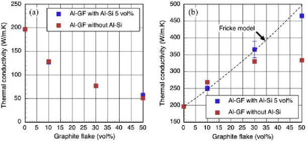
Figure 6 presents the thermal conductivities of the analyzed Al–GF composites. Although thermal conductivity was measured in three different samples, values were similar among samples with the same GF volume fraction. Thermal conductivities in the transverse direction of GFs decreased with increasing GF volume fraction due to the low thermal conductivities of GF in this direction (see Fig.6a).14-16 In contrast, thermal conductivities in the in-plane direction were directly linked to the relative densities of the Al–GF composites (see Fig. 6b); for samples with more than 30 vol% GF, thermal conductivities of composites fabricated without Al-Si were lower than of those fabricated with 5 vol% Al-Si, but were the same as in those produced with less than 10 vol% GF. This result indicates that the thermal conductivity of the Al–GF composite is determined by its densification level, not Al/GF interfacial conditions. Note that a high thermal conductivity was also observed in the Al–GF composite fabricated without Al-Si, which exhibited a nano space along the Al/GF interface. This result implies that the applied heat was effectively transferred through the graphite
sheets bridging Al matrix and GF.
We estimated the theoretical thermal conductivity of the Al–GF composite in the in-plane direction of GF by using the following equation for heterogeneous two-component systems, as suggested by Fricke et al.:20
r m f m r r m f m r m c K K V K n K K K V n K n K K K 1 1 1 ...(2)where Kc, Km and Kr stand for the thermal conductivities of composite, matrix and reinforcement, respectively. In the present study, the thermal conductivity of the aluminum matrix, Km, was 200 W/m・K, i.e., the experimental value obtained for the aluminum itself, which was fabricated via the same process. As it is difficult to experimentally measure the thermal conductivities of individual GFs in the in-plane direction, Kr was thus assumed to be 1000 W/m・K, based on the thermal conductivity of the highly oriented graphite bulk in the in-plane direction as reported by Murakami et al.14 V
f is the volume fraction of reinforcement, and n is the shape factor, an indefinite number dependent on the shape of the reinforcement, which is given by
/ 3
n …(3)
where is sphericity.21 Concerning GF, Jefferson et al. have reported that is about 0.5.21,22 Furthermore, it has also been established that the experimental results for composites in which the reinforcement has an aspect ratio larger than 5, are consistent with theoretical data if is 0.5.21 In the present study, the aspect ratio of GF was estimated to be larger than 10, based on flake diameter (32 mesh; approximately 500 m) and thickness (30 ~ 50 m). Hence, substituting = 0.5 into equation (3), n is calculated as 6. The estimated theoretical thermal conductivity of the Al–GF composite (Kc) is indicated by the black broken line in Fig. 6b. This result shows that the outstanding thermal conductivity of GF is basically brought out in the Al–GF composite when the latter is fully-dense.
3.3. Thermal expansion coefficient (TEC)
Figure 7 shows the TEC of the tested Al–GF composites in the in-plane direction of GFs. It has been reported that the TEC of graphite bulk in the a-b plane is small (−1.0×10⁻⁶ /K at room temperature).14 Nevertheless, the average TECs of the Al–GF composites remained higher than 22.0×10⁻⁶ /K, but fell slightly with an increase in the volume fraction of GF; the outstanding TEC of GF was thus not reflected in the Al–GF composite. This result implies that the damaged inner structure of GF in proximity to the Al/GF interface is not strong enough to bear the load resulting from thermal stress.
In many cases, matrix/reinforcement interfacial strength dominates the thermomechanical and mechanical properties of composite materials. Concerning Al-based composites, it has been reported that the creation of Al4C3 at the interface acts to enhance the interfacial strength.6,7 However, it seems that interfacial Al4C3 formation does not enhance the mechanical properties of the Al–GF composite, because the interlaminar strength of GF is smaller than the Al/GF interfacial strength. In this regard, Estili et al. have previously documented interfacial load transfer via compressive stress in a multi-walled carbon nanotube (MWCNT) reinforced Al2O3 matrix composite.23 We also reported an improvement in the tensile strength of a MWCNT reinforced Al matrix composite, subject to a compressive stress inside and with an intimate interface, without the presence of Al4C3 crystals.6 It is therefore likely that the application of compressive stress during the fabrication process prevents damage to the GF microstructure (especially to that in close proximity to the Al/GF interface) via thermal stress, thus bringing out the outstanding thermomechanical properties of GF in the Al–GF composite.
4. Conclusion
A fully-dense Al–GF composite was fabricated via hot pressing, with a small amount of Al-Si introduced in the Al matrix powder. Although the Al/GF interface initially seemed intimate in SEM micrographs, TEM observation revealed that thermal stress created a nano space along the interface.
Moreover, the observed unique bridging of sticky graphite sheets indicated that this nano space was created within GF in proximity to the Al/GF interface, and not at the Al/GF interface itself. Although the addition of Al-Si prevented the creation of such nano space, it also caused the disarray of the inner structure of GF in proximity to the Al/GF interface. The results clearly demonstrate that the interlaminar strength of GF (i.e. van der Waals binding affects between graphite sheets) in proximity to the Al/GF interface is weaker than the Al/GF interfacial strength. Therefore, it seems that the GF interlaminar strength is the dominant determinant of the thermomechanical and mechanical properties of the Al–GF composite.
The thermal conductivity of the Al–GF composites was directly correlated with their densities, thus indicating that composite thermal conductivity is determined by the densification level, not the Al/GF interfacial conditions, i.e. the bridging of graphite sheets and the disarray of the inner structure of GF both contribute to effective heat transfer. Furthermore, the consistency between the experimental and estimated theoretical thermal conductivities shows that the outstanding thermal conductivity of GFs is largely brought out in fully-dense Al–GF composites.
In contrast, the outstanding TEC of graphite was not reflected in the produced Al–GF composites. This result implies that the damaged inner structure of GF in proximity to the Al/GF interface (i.e. the bridging of sticky graphite sheets and the disarray of the GF inner structure) is not strong enough to bear the load resulting from thermal stress. For the analyzed Al–GF composite, whose mechanical properties are dominated by the interlaminar strength of the reinforcement, it is likely that the application of compressive stress during the fabrication process prevents thermal stress at the Al/GF interface, thus bringing out the outstanding thermomechanical properties of GF in the final product.
References
(2) Lai, S.; Chung, D.D.L. Phase distribution and associated mechanical property distribution in silicon carbide particle-reinforced aluminum fabricated by liquid metal infiltration. J. Mater.
Sci. 1994, 29, 2998–3016.
(3) Lai, S.; Chung, D.D.L. Superior high-temperature resistance of aluminum nitride particle-reinforced aluminum compared to silicon carbide or alumina particle-particle-reinforced aluminum. J.
Mater. Sci. 1994, 29, 6181–6198.
(4) Lalet, G; Kurita, H.; Heintz, J-M.; Lacombe, G.; Kawasaki, A.; Silvain, J-F. Thermal expansion coefficient and thermal fatigue of discontinuous carbon fiber-reinforced copper and aluminum matrix composites without interfacial chemical bond. J. Mater. Sci. 2014, 49, 397–402.
(5) Lalet, G.; Kurita, H.; Miyazaki, T.; Kawasaki, A.; Silvain, J-F. Thermomechanical stability of a carbon fiber-reinforced aluminum matrix composite fabricated by spark plasma sintering in various pulse conditions. Mater. Lett. 2014, 130, 32–35
(6) Kurita, H.; Kwon, H.; Estili, M.; Kawasaki, A. Multi-walled carbon nanotube-aluminum matrix composites prepared by combination of hetero-agglomeration method, spark plasma sintering and hot extrusion. Mater. Trans. 2011, 52(10), 1960–1965.
(7) Kwon, H.; Kurita, H.; Leparoux, M.; Kawasaki. A. Carbon nanofiber reinforced aluminum matrix composite fabricated by combined process of spark plasma sintering and hot extrusion.
J. Nanosci. Nanotech. 2011, 11, 4119–4126.
(8) Smagorinski, M.E.; Tsantrizos, P.G.; Grenier, S.; Cavasin, A.; Brzezinski, T.; Kim, G. The properties and microstructure of Al-based composites reinforced with ceramic particles. Mater.
Sci. Eng. A 1998, 244, 86–90.
(9) Ruch, P.W.; Beffort, O.; Kleiner, S.; Weber, L.; Uggowitzer, P.J. Selective interfacial bonding in Al(Si)-diamond composites and its effect on thermal conductivity. Com. Sci. and Tech. 2006, 66, 2677–2685.
(10) Bakshi, S.R.; Balani, K.; Agarwal. A. Thermal conductivity of plasma-sprayed aluminum oxide-multiwalled carbon nanotube composite. J. Am. Ceram. Soc. 2008, 91(3), 942–947.
(11) Yoshida, K.; Morigami, H. Thermal properties of diamond/copper composite material.
Microelectronics Reliability. 2004, 44, 303–308.
(12) Pierson, H.O. Handbook of Carbon, Graphite, Diamond and Fullerenes. Noyes Publications,
Park Ridge, New Jersey, USA, 1993,194–195.
(13) Veillère, A.; Heintz, M.; Chandra, N.; Douin, J.; Lahaye, M.; Lalet, G.; Vincent, C.; Silvain J-F. Influence of the interface structure on the thermo-mechanical properties of Cu–X (X = Cr or B)/carbon fiber composites. Mater. Res. Bull. 2012, 47, 375–380.
(14) Murakami, M.; Nishiki, N.; Nakamura, K.; Ehara, J.; Okada, H.; Kouzaki, T.; Wakatabe, K.; Hoshi, T.; Yoshimura, S. High-quality and highly oriented graphite block from polycondensation polymer films. Carbon. 1992, 30(2), 255–262.
(15) Nelson, J.B.; Riley, D.P. The thermal expansion of graphite from 15°c. to 800°c.: part I. Experimental. Proc. Phys. Soc. 1945, 57, 477.
(16) Spain, I.L.; Ubbelohde, A.R.; Young, D.A. Electronic properties of well oriented graphite. Phil.
Trans. Roy. Soc. 1967, 262, 345–386.
(17) Chen, J.K.; Huang, I.S. Thermal properties of aluminum–graphite composites by powder metallurgy. Compos. Part B. 2013, 44, 698–703.
(18) Mizuuchi, K.; Inoue, K.; Agari, Y.; Morisada, Y.; Sugioka, M.; Tanaka, K.; Takeuchi, T.; Tani, J.; Kawahara, M.; Makino, Y. Processing of diamond particle dispersed aluminum matrix composites in continuous solid-liquid co-existent state by SPS and their thermal properties.
Compos. Part B. 2011, 42, 825–831.
(19) Lalet, G.; Kurita, H.; Miyazaki, T.; Kawasaki, A.; Silvain J-F. Microstructure of a carbon fiber-reinforced aluminum matrix composite fabricated by spark plasma sintering in various pulse conditions. J. Mater. Sci. 2014, 49, 3268–3275.
(20) Fricke, H. A mathematical treatment of the electric conductivity and capacity of disperse systems. Phys. Rev. 1924, 24, 575–587.
(21) Hamilton, R.L.; Crosser, O.K. Thermal conductivity of heterogeneous two-component systems.
Ind. Eng. Chem. Fundamen. 1962, 1(3), 187–191.
(22) Jefferson, T.B.; Witzell, O.W.; Sibbitt, W.L. Ind. Eng. Chem. 1958, 50, 1989–1992.
(23) Estili, M.; Kawasaki A. Engineering strong intergraphene shear resistance in multi-walled carbon nanotubes and dramatic tensile improvements. Adv. Mater. 2010, 22, 607–610.
Figure captions
Figure 1 SEM micrographs of starting materials; (a) Al powder, (b) Al-Si11.3 at% alloy powder, and (c) Graphite flakes.
Figure 3 SEM micrographs of Al–GF composites; (a) without Al-Si, (b) Al/GF interface in Al–GF composite without Al-Si, (c) with 5 vol% Al-Si, and (d) Al/GF interface in Al–GF composite with 5 vol% Al-Si.
Figure 4 TEM micrographs of Al–GF composites without Al-Si; (a) overall view, (b) Al/GF interface, (c) the joint part of sticky GF sheets at the Al/GF interface, and (d) Al particle boundaries.
Figure 5 TEM micrographs of Al–GF composites with 5 vol% Al-Si; (a) the intimate Al/GF interface, (b) the inner structure of GF in proximity to the intimate Al/GF interface, (c) the fractured Al/GF interface, and (d) Al particle boundaries.
Figure 6 Thermal conductivity of Al–GF composites in the (a) transverse and (b) in-plane directions of graphite flakes.
Figure 7 Thermal expansion coefficient of Al–GF composites in the in-plane direction of graphite flakes.