HAL Id: hal-02908169
https://hal.archives-ouvertes.fr/hal-02908169
Submitted on 3 Feb 2021
HAL is a multi-disciplinary open access
archive for the deposit and dissemination of
sci-entific research documents, whether they are
pub-lished or not. The documents may come from
teaching and research institutions in France or
abroad, or from public or private research centers.
L’archive ouverte pluridisciplinaire HAL, est
destinée au dépôt et à la diffusion de documents
scientifiques de niveau recherche, publiés ou non,
émanant des établissements d’enseignement et de
recherche français ou étrangers, des laboratoires
publics ou privés.
pharmaceutical development: from mg
×h-1 to kg×h-1 of
an unsymmetrical urea
Leo Leroyer, Laurent Prat, Michel Cabassud, Christophe Gourdon, Odile
Dechy-Cabaret, Matthieu Barthes, Philippe Camus, Stephane Hattou
To cite this version:
Leo Leroyer, Laurent Prat, Michel Cabassud, Christophe Gourdon, Odile Dechy-Cabaret, et al..
Trans-position of a triphosgene-based process for pharmaceutical development: from mg
×h-1 to kg×h-1
of an unsymmetrical urea. Green Processing and Synthesis, De Gruyter, 2013, 2 (3), pp.239-250.
�10.1515/gps-2013-0026�. �hal-02908169�
Leo Leroyer , Laurent Prat* , Michel Cabassud , Christophe Gourdon , Odile Dechy-Cabaret ,
Matthieu Barthes , Philippe Camus and Stephane Hattou
Transposition of a triphosgene-based process for
pharmaceutical development: from mg · h
-1
to kg · h
-1
of an unsymmetrical urea
Abstract: A two reaction synthesis of a urea, using triphos-gene, was studied. The objective was to transpose the process from laboratory scale to pre-industrial plant. The whole study was performed in a continuous process, adapting the characteristic dimensions and length of the reactor. In this paper, the development of the process is presented, and the choices about safety and operating conditions constraints are discussed. The final operation allows a 70% global yield in a 7 week study. Furthermore, the use of microreactors not only permits an exhaustive study of the process operating parameters, but also pro-vides feedback on the developed chemistry itself. The results obtained are a demonstration of the use of con-tinuous processes in small scale reactors for complex molecule development. The mg · h -1 to kg · h -1 is a key
trans-position in the pharmaceutical industries project develop-ment, as it can help to accelerate the first lot production used in toxicological or pre-clinic stages.
Keywords: fast process development; intensification; microreactor; pharmaceuticals; reaction engineering.
*Corresponding author: Laurent Prat, CNRS, Laboratoire de G é nie Chimique (LGC), 4 all é e Emile Monso, BP 84234, F-31030 Toulouse, France; and Universit é de Toulouse, INPT, UPS, Toulouse, France , e-mail: laurent.prat@ensiacet.fr
Leo Leroyer: CNRS, Laboratoire de G é nie Chimique (LGC), 4 all é e Emile Monso, BP 84234, F-31030 Toulouse, France ; CNRS, Laboratoire de Chimie de Coordination (LCC), 4 all é e Emile Monso, F-31030 Toulouse, France ; and Universit é de Toulouse, INPT, UPS, Toulouse, France
Michel Cabassud and Christophe Gourdon: CNRS, Laboratoire de G é nie Chimique (LGC), 4 all é e Emile Monso, BP 84234, F-31030 Toulouse, France ; and Universit é de Toulouse, INPT, UPS, Toulouse, France
Odile Dechy-Cabaret: CNRS, Laboratoire de Chimie de Coordination (LCC), 4 all é e Emile Monso, F-31030 Toulouse, France ; and Universit é de Toulouse, INPT, UPS, Toulouse, France
Matthieu Barthes, Philippe Camus and Stephane Hattou: SANOFI-AVENTIS, Recherche et développement, 371, rue du Professeur Joseph Blayac, 34184, Montpellier cedex 04, France
1 Introduction, context and
objectives
Process intensification (thanks to miniaturization and batch to continuous transposition) opens up numerous perspectives in terms of chemical production at an indus-trial scale [1]. Indeed, decreasing the device size allows a reduction of technology constraints to the benefit of chem-istry [2 – 4]. Continuous microscale devices are character-ized by high surface to volume areas, which provide them with good thermal capacity [5 – 7]. In addition, intensifica-tion accelerates reacintensifica-tion rates and then reduces reactive hold-up. This is of great importance when dealing with systems facing safety issues due to hazardous reagents [8]. In addition, for the same reasons these technologies, often called “ flow chemistry ” by chemists, are now con-sidered as real additional tools for the modern chemist [9 – 11].
A complete implementation of an intensified system often requires an important amount of information on the system, including physicochemical parameters, thermoki-netic models, and thermal and mixing characterization of the reactors used [12, 13]. The global objective of this paper is to focus on a batch to continuous transposition of the synthesis of a urea under industrial constraints. These constraints are of two kinds: (i) time and products con-sumed must be reduced to the minimum, which implies that no complete model can be obtained; (ii) the process must be transposed in the kilo-lab industrial plant. It is a flexible batch-based plant dedicated to the production of intermediate product quantities (around the kilogram). The objectives of this paper are: (i) to describe the different steps of the transposition from batch to con-tinuous and from mg · h -1 to kg · h -1 of the production of an
unsymmetrical urea; (ii) to analyze the experimental results obtained in terms of process design and in terms of intrinsic chemistry; and (iii) to put into perspective the project results in terms of spent time, safety and product constraints.
1.1 Studied system
A brief summary of the synthetic ways explored by the Chemical Development Department of Sanofi-Aventis in order to produce the urea is given.
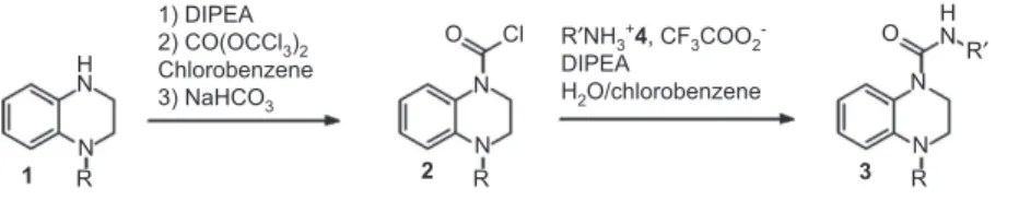
The studied reactions ( Figure 1 ) correspond to the phosgenation of the secondary amine 1 , leading to the car-bamoyl chloride 2 , followed by the urea 3 formation via the primary amine 4 addition. The proposed urea 3 was a pharmaceutical target molecule developed by Sanofi-Aventis, obtained after a 14 step convergent synthesis. The urea formation corresponds to the last one. Optimization and scale-up of the latter have thus been considered as an important issue for the industrial project.
Initially, 2 was formed by adding a phosgene solu-tion in toluene to 1 . According to the toxicity of this reagent, other methodologies have been studied, including imidazolide or isopropenyl chloroformate for-mation attempts, which unfortunately did not produce the urea 3 . The pathway via 2 has been thus reassessed by replacing the phosgene solution with the more stable analogous triphosgene bis(trichloromethyl) carbonate (BTC). During this study, the best results were obtained with chlorobenzene as the solvent and diisopropyleth-ylamine (DIPEA) as the base. For the second reaction, Schotten-Baumann conditions from the amine 4 trif-luoroacetic acid (TFA) salt led to better conversions and easier setting up, compared to the reaction in organic solvents [dimethylformamide (DMF), toluene, acetoni-trile] in the presence of DIPEA, but with low reproduc-ibility and low robustness on extrapolation.
Even if the urea could be prepared successfully by the previously described method, the targeted produc-tion on a large scale would be restricted by numerous constraints, in particular for the first reaction. Indeed, the reaction exothermicity ( Δ r H = -595 kJ · mol -1 ) and the
low boiling point of phosgene (8 ° C), require a rigorous control of the temperature. Moreover, the use of a BTC excess led to the formation of phosgene remaining at the end of the reaction, which has to be hydrolyzed by a basic treatment. As the goal was to prepare the urea 3 at an industrial scale, diminution of phosgene throughput,
by reducing the reactor volume, was essential and envi-sioned by transposing the reaction to a continuous process.
1.2 Preliminary analysis and methodology
developed
Firstly, only the first reaction has been studied in chloro
-benzene, and the conditions have been repeated in batch to appreciate the reaction behavior. Even if the conversion was quite good (93% purity after treatment without purification), precipitation of DIPEA chlorhy-drate and product 2 encourages us to find an alternative solvent. While pyridine leads to a rapid consumption of
1, along with the production of a large amount of
impu-rities, notably pyridinium salts, dichloromethane had a good impurity profile (96% purity after treatment), but required a second addition of BTC (0.2 equivalents) to achieve completion of the reaction. By lowering the DIPEA excess (1.2 instead of 2.5 equivalents), while keeping 0.5 BTC equivalent and dichloromethane as the solvent, complete consumption of 1 has been observed by thin layer chromatography (TLC), but liquid chroma-tography-mass spectrometry (LC-MS) analysis after treat-ment has shown the presence of an impurity attributed to the trichloromethylcarbamate intermediate 5 . Even if it was proposed as the intermediate [14], the observation of trichloromethylcarbamate 5 is moreover singular, as only a few examples mention the presence of this inter-mediate during the preparation of ureas from amines and BTC. Only three examples show experimental charac-terizations, one by mass spectroscopy [15] and two by 1 H
nuclear magnetic resonance (NMR) [16, 17], which do not discriminate between the trichloromethylcarbamate and the carbamoyl chloride. In other cases, the intermediates are not fully characterized [18] or are not isolated [19]. Other syntheses are supposed to involve trichloromethyl-carbamate or carbonate intermediates, but the latter were never isolated [20, 21].
The following pathway can thus be proposed ( Figure 2 ). N H N R N N R O Cl N N R O R′ H N R′NH3+4, CF3COO2 -DIPEA H2O/chlorobenzene 1) DIPEA 2) CO(OCCl3)2 Chlorobenzene 3) NaHCO3 1 2 3
2 First experimental step:
milligrams per hour (mg · h
-1)
2.1 Microfluidic device and operating
conditions for the carbamoyl chloride 2
formation
Because of the possible formation of agglomerates during the process, perfluoroalkoxy (PFA) tubes connected with polyether ether ketone (PEEK) tee micromixers were chosen for practical reasons, as they can be cut and replaced easily and inexpensively. To combine classical flow velocities (3.33.10 -2 m · s -1 ) for good thermal exchange,
a length of 8 m, with a residence time of 4 min, was firstly investigated (later, the residence time was changed by varying the length).
The microreactor used was composed of two PFA tube reactors { R 1 [inner diameter φ = 500 μ m, length l = (1 – 8) m, R 2 [inner diameter φ = 500 μ m, length l = 1 m] } connected by three PEEK tee micromixers (M 1 , M 2 and M 3 , inner diame-ter = 500 μ m). R 1 was used for the phosgenation and R 2 for the neutralization with NaHCO 3 . The whole system ( Figure 3 ) was submerged in a controlled temperature bath. The reagent solutions were poured in to a glass syringe and brought by syringe pumps to the micromixers with flow rate control, while the samples were collected in small tubes at ambient temperature.
In addition to chlorobenzene, dichloromethane was also used, as precipitation is avoided with this solvent. Experimental operating conditions were: tem-perature = 20 ° C; residence time = 1 – 10 min; BTC equivalent
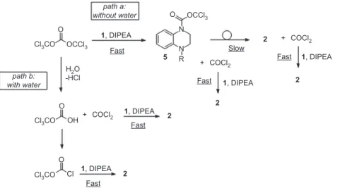
Cl3CO Cl3CO Cl3CO Cl OCCl3 COCl2 + COCl2 + COCl2 + OCCl3 O O O OH O path a: without water path b: with water N N R 5 2 2 2 2 2 1, DIPEA 1, DIPEA 1, DIPEA 1, DIPEA 1, DIPEA H2O -HCl Fast Fast Fast Fast Fast Slow
Figure 2 Proposed mechanism for the addition of 1 on BTC in presence of diisopropylethylamine (DIPEA) (path a). Proposed mechanism underlining the role of water in the reaction (path b).
BTC, solvent DIPEA, solvent T(°C) R1 R2 M1 M3 M2 1,Solvent aq. NaHCO3
Figure 3 Schematic view of used set-up for carbamoyl chloride formation study.
0.37 – 0.5; DIPEA equivalent 1.1 – 2.5. In order to restrain eventual clogging problems due to precipitation, a dilu-tion of about 5 compared to batch experiments was used in the continuous reactor (about 6 g · l -1 instead of 33 g · l -1 ).
Experimental details, including a description of the analytical method, are reported in the Appendices Section.
2.2 Results and discussion
2.2.1 Preliminary results
In dichloromethane, whatever the residence time, DIPEA equivalents numbers seem to have no noticeable effect. In all cases, 2 was obtained along with 5 in proportions of about 55/45. Consumption of 1 increased when the BTC equivalent increased and was complete for all values over 0.4.
This is in agreement with the previously proposed pathway: the first reaction, corresponding to the attack of a first amine 1 on BTC, occurs well and very quickly by formation of the intermediate 5 along with the release of a phosgene molecule. The latter can react promptly with a second amine 1 to form the carbamoyl chloride 2 . However, the requested time for rearrangement of 5 seems to be higher than the residence time. Indeed high-perfor-mance liquid chromatography (HPLC) analysis of a 2 / 5 mixture sample obtained at the reactor output, then kept for 48 h at 5 ° C, showed a complete conversion into 2 along with impurities formation. After 16 h at 5 ° C, conversion was, however, incomplete, still with a presence of 5 .
In standard chlorobenzene, the total conversion into
2 was observed in all cases, except when BTC excess was
highly reduced without DIPEA stoichiometry adjustment. When the concentration was restored to the one used in batch conditions (30 g · l -1 in a continuous reactor), a slight
decline of conversion into 2 was observed (97%), along with the occurrence of a small quantity of 5 (3%).
2.2.2 Influence of water
During the experimental conditions study, it appeared that the water present in the solvent had an influence on the conversion into 2 . Indeed, use of anhydrous chloro-benzene (dried over molecular sieves) led to a signifi-cant amount of 5 being obtained, to the detriment of the expected 2 (around 20%), whatever the operating conditions.
In order to validate the water effect on the reaction, the latter experiments were undertaken in anhydrous or resat-urated chlorobenzene (the same chlorobenzene dried over a molecular sieve was rehydrated by the addition of water, decantation, and then separation). This procedure leads to an eventual effect of the molecular sieve. The temperature was 20 ° C, the residence time 2 min, the DIPEA equivalent from 1.1 to 2.5 and the BTC equivalent from 0.37 to 0.5.
Firstly, BTC was introduced in to the anhydrous chlo-robenzene, while 1 /DIPEA mixture was in a solution in anhydrous or resaturated chlorobenzene. Whatever the conditions, about 80% of 2 was obtained, along with the presence of about 10% of 5 . However, when the BTC solution was prepared in resaturated chlorobenzene, the conversion into 2 was > 99%, independent of the nature, anhydrous or not, of the 1 /DIPEA solution. It thus seems that only the BTC solution needs to be hydrated.
Furthermore, various experiments were carried out in anhydrous chlorobenzene to promote the conversion of 5 into 2 .
Increasing the quenching solution flow and/or the residence time did not have any influence, confirming that
5 , once formed, can be converted into 2 only very slowly.
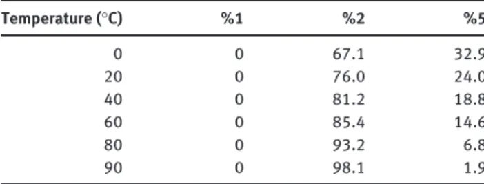
Increasing the temperature from 0 ° C to 90 ° C allows a complete conversion of 5 into 2 . Table 1 shows the evo-lution of 5 when the reaction temperature goes from 0 ° C (with a conversion into 2 of 67%) to 90 ° C (98% conver-sion) with a residence time of 5 min, 2.5 DIPEA equivalent and 0.5 BTC equivalent.
Two conclusions can be drawn from these experi-ments: (i) the water presence in the solvent has a positive influence on the process; (ii) the higher the temperature, the faster 5 is converted into 2 . This temperature increase also favors the BTC decomposition into phosgene, which reacts with 1 to directly yield 2 .
On the basis of these results, an alternative pathway can be proposed, underlining the role of water in the reac-tion ( Figure 2 , path b). While the path (a ) corresponds to the one previously described, changes are provided with path (b ) , in the presence of water. In this case, even before the addition of 1 , water contained in the solvent can react with BTC which decomposes into phosgene and the corre-sponding hydrogen carbonate [22]. The latter can a priori be converted into diphosgene in the media (by reacting with phosgene, di- or triphosgene or eventually by the chlorides present) and can thus react with 1 to give 2 along with phosgene, immediately consumed to produce another molecule of 2 .
Whereas BTC is widely described as analogous to phosgene [23, 24] (showing a similar behavior), the present study in continuous mode has highlighted that its reactiv-ity can differ depending on the conditions.
2.3 Coupling the second reaction
First preliminary experiments were performed, using the same experimental set-up as previously (the last syringe containing compound 4 and DIPEA in dichloromethane). These experiments show that the characteristic time of
Table 1 Effect of temperature on conversion of 1 into 2 in anhydrous chlorobenzene (no presence of compound 1 ).
Temperature ( ° C) %1 %2 %5 0 0 67.1 32.9 20 0 76.0 24.0 40 0 81.2 18.8 60 0 85.4 14.6 80 0 93.2 6.8 90 0 98.1 1.9
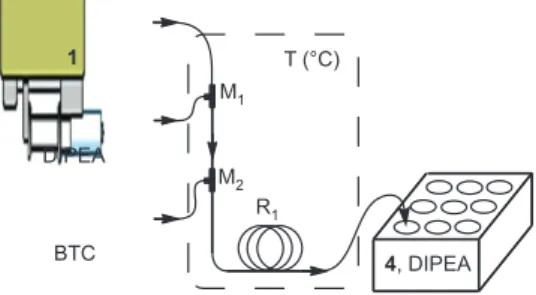
second reaction was > 2 h and, due to urea 3 precipitation, the initial concentration of compound 1 was divided by 30. These constraints led to the choice of a fed-batch mode ( Figure 4 ). This choice is not in opposition with the indus-trialization objective of the work. Indeed, the hazardous generation of 2 could occur in a secure continuous reactor, while the urea 3 formation could occur in a conventional batch reactor containing a solution of 4 and DIPEA.
The operating conditions used were: residence time in the first reactor was maintained at 2 min (sufficient to form 2) ; residence time in the second reactor ranged from 2 to 1000 min; BTC equivalent of 0.36; DIPEA equivalent of 1.08. Each sample corresponded to a 2 min reactor output pouring into a hemolysis tube containing 4 (1.2 equiva-lents) and DIPEA (1.2 equivaequiva-lents) in dichloromethane, chlorobenzene or acetonitrile.
A kinetic study of the second reaction was undertaken in these conditions for different solvents. Experimental details are reported in the Appendices section.
Figure 5 shows the results of this study.
Conversion into 3 was much faster in acetonitrile than in dichloromethane (96% vs. 42% after 40 min). In chloro-benzene, the reaction seemed even slower, with a conver-sion reaching only 10% after 16 h.
Acetonitrile was thus chosen to implement the second reaction for the following steps of the study.
3 Second experimental step:
ten grams per hour (10 g · h
-1)
3.1 Experimental methods
As mentioned in the previous scale, in order to respect the industrial objectives, fed-batch mode was conserved for the second reaction. Thus, only reactor tube length (along with flow rate adjustments) was increased, while the other parameters were kept unchanged (reactor inner
diameter, concentration), so as to minimize scale change impact. Temperature and DIPEA equivalent were kept to 20 ° C and 1.2, respectively. The initial concentration of
1 was 22 g · l -1 . Commercial non dried chlorobenzene was
used as the solvent.
Owing to the flow rates and volumes proposed, the introduction of the reagents was ensured by HPLC pumps. A three way valve was installed at the contin-uous reactor. It allows to send the output flow either toward a “ waste ” Erlenmeyer during the stationary state, or toward the Erlenmeyer containing the 4 and DIPEA solution ( Figure 6 ).
Concerning the first reaction (in continuous mode), as the reactor length was elongated to 30 m instead of 1 m, while reducing the residence time to 1 – 2 min, the flow velocity was increased to 0.25 – 0.5 m · s -1 instead of
0.0083 m · s -1 , resulting a priori in a better heat transfer.
However, contrary to syringe pumps used at the micro-scale, HPLC pumps may cause flow rate oscillation.
For the second reaction, as it is conducted in batch mode, elongation of the addition time induced initial and local stoichiometry changes, resulting in a strong 4 excess at the beginning of the addition (the addition time is 10 min). In the batch reactor, with a magnetically stirred Erlenmeyer, the mixing efficiency may decrease, while thermal effects changes are difficult to predict.
Experimental details are reported in the Appendices section.
3.2 Results and discussion
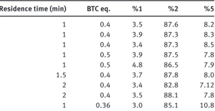
Firstly, generation of the carbamoyl chloride 2 was studied by using 10 min output flow of the continuous reactor into a quenching solution placed in the Erlenmeyer. Results are presented in Table 2.
A first test showed a good conversion of 1 into 2 , but
5 was also produced (about 10%). Increasing BTC
equiva-lents or the residence time did not lead to any improve-ment. In addition, no impact was observed with the use of chlorobenzene saturated with water for the preparation of BTC solution.
The second reaction was performed according to the previously described method. Experiments, correspond-ing to two 20 min additions into the 4 solution, were achieved. DIPEA stoichiometry used for the first step study was kept (1.2 equivalents). While a new unattrib-uted impurity was detected in a low quantity after 5 min, with finally, complete disappearance, the conversion into
3 was 48% after 5 min and increased slowly to 55% after
150 min. The results are presented in Table 3.
DIPEA T (°C) R1 M1 M2 1 4, DIPEA BTC
Figure 4 Schematic view of fed-batch system used for the two steps sequence study.
Two hypotheses can be proposed to explain the pres-ence of 5 :
– Flow speed increase in the reactor (0.5 m · s -1 instead
of 0.0083 m · s -1 ), resulting in a better heat transfer; a
temperature increase could thus be avoided in these conditions. As shown previously, temperature is favorable to the decomposition of 5 into 2 . The good thermal performances of the continuous mode at a small reactor scale should be unfavorable.
– Poorly controlled stoichiometry at the tee micro-mixer, due to flow oscillation generated by the HPLC pumps.
Concerning the second reaction, the observed maximum at 55% can be explained by protonation of 4 (as was men-tioned during the first step of the study). In addition, the presence of 5 (about 10%) is also observed in the same
T (°C) R1 M1 "Batch" "Continuous" 4, DIPEA "Waste" K2CO3 1, DIPEA BTC
Figure 6 Schematic view of fed-batch system.
0 20 40 60 80 100 0 100 200 300 400 500 600 700 800 900 1000
Residence time (min)
Urea (%
)
Chlorobenzene Dichloromethane Acetonitrile
Figure 5 Effect of residence time in fed-batch mode on conversion of 1 into 3 . (20 ° C; R 1 : l = 1 m, φ = 500 μ m, τ = 2 min, v = 8.33.10
-3 m · s -1 , 0.098 ml · min -1 , [ 1 ] = ~33 g · l -1 in chlorobenzene, 0.36 eq. BTC, 1.08 eq. DIPEA).
Table 2 Study of the conversion of 1 into 2 at about 10 g · h -1 .
Residence time (min) BTC eq. % 1 % 2 % 5
1 0.4 3.5 87.6 8.2 1 0.4 3.9 87.3 8.3 1 0.4 3.4 87.3 8.5 1 0.5 3.9 87.5 7.8 1 0.5 4.8 86.5 7.9 1.5 0.4 3.7 87.8 8.0 2 0.4 3.4 82.8 7.12 2 0.4 3.5 88.1 7.8 1 0.36 3.0 85.1 10.8
Table 3 Conversion of 1 into 3 study at about 10 g · h -1 .
Time in batch reactor (min) % 1 % 2 % 3 % 5 % n.i.p
5 1.4 38.1 47.9 11.0 1.6 35 1.2 32.9 53.7 10.9 1.3 50 1.2 32.5 54.7 10.9 0.7 150 0 33.0 55.5 11.5 0 n.i.p., correspond to non identified product.
proportions at the end of the second reaction as 5 is not involved in the second reaction.
In conclusion, novel difficulties appeared with this first scale-up: the presence of an impurity which slowly disap-pears, enhancement of the formation of 5 and limitation of conversion into 3 . However, the results allow reaching the kilo-lab industrial production plant without further experi-ments. Analysis of these intermediate scale results provide interesting points to work on for further process studies (the temperature level at the very beginning of the first reaction and local stoichiometry and mixing for the second one.).
4 Third experimental step:
kilos per hour (kg · h
-1)
4.1 Experimental methods
For kilo-lab implementation, a new scale-up was neces-sary: in addition to the reactor tube length, the inner
diameter was also increased (1.55 mm instead of 0.5 mm). The reactor made out of the tubing was wrapped around a stainless steel bar to assure thermal behavior. Then, for safety reasons, the reactor was submerged in a 20% soda bath.
1 /DIPEA solution was introduced with a gear pump,
while the BTC solution was delivered by a PTFE peristal-tic pump to avoid corrosion. The reactor length was 20 m (instead of 30 m in previous study), to conform to the limi-tations of the pump and to reduce the fluid velocity.
During steady state establishment, the reactor output was redirected to a “ waste ” reactor containing soda solu-tion via a three way valve. In addition, another three way valve was installed at the continuous reactor output, allowing collection of the sample for analysis before intro-duction into the reactor containing the 4 /DIPEA solu-tion. The scheme of the installation is the same as shown in Figure 6 (with 100 l stirred tank reactors instead of Erlenmeyers).
Modifications are expected on system behaviors due to technological choices. The reactor was shortened to 20 m and the inner diameter was increased to 1.55 mm. Then, the flow velocity is slightly lower (0.33 m · s -1 instead
0.5 m · s -1 ), to maintain heat transfer efficiency. The most
important, is the modification of the inner diameter, which may increase mixing and heat transfer character-istic times. Oscillation of flow rates could also happen because of the used pumps, in particular with the peri-staltic pump (flow oscillation amplitudes were about 20% with the peristaltic pump and 5% with the gear pump).
The same expectations as for the first scale-up are also available for the second reaction in batch, namely, change of initial and local stoichiometry and modification of thermal effects, while mechanical stirring of the reactor should enhance the mixing efficiency.
Experimental details are reported in the Appendices section.
4.2 Results and discussion
According to the allowed time (the industrial kilo-lab plant was stopped for the study), only a 1 day experiment was planned, corresponding to the optimal conditions: in chlorobenzene saturated with water as the solvent, 0.36 BTC equivalents and 1.08 DIPEA equivalents for the first reaction (generation of 2) were used. Then, the continuous reactor output was fed into the batch reactor containing the
4 /DIPEA solution in acetonitrile. The addition was stopped
after 5 h of feeding (to reach stoichiometry) and the reactor stayed in stirring mode under temperature control.
The analysis between 1h 45 min and 6 h 10 min after steady state was reached in the continuous part, showed a very weak conversion progress, with a limitation at 70% (see Table 4). A significant amount of 5 was also detected (about 15 – 20%), but disappeared after 72 h in favor of 2 , suggesting that 5 had been converted slowly into 2 .
However, the observed stagnation of conversion into 3 can be explained by two phenomena:
– Inhibition of reactivity of 4 left in the media, due to its protonation, was also observed during the second scale study. The increase in reaction time allowed this acid-base equilibrium.
– Consumption of 4 via reaction with the generated phosgene during 5 degradation, to form an isocyanate suitable for leading to a symmetrical urea by addition of another 4 molecule.
5 Conclusion
The objective of the project was to implement a two step synthesis of an unsymmetrical urea, using triphosgene as a phosgenation agent. Classically implemented in a batch reactor at lab-scale, the transposition to the indus-trial kilo-lab production plant was not directly possible for safety reasons, due to phosgene. Indeed, the equivalent batch reactor volume necessary to produce a kilo of prod-ucts involved too much phosgene. A continuous process was then identified as a possible way to solve this issue.
Therefore, the objective of the study was to implement a continuous process with a constraint of time and quan-tity used for the preliminary experiments. Two process scales were studied (mg · h -1 and 10 g · h -1 ) before the final
scale (kg · h -1 ). Because of the exothermic reactions and
very low characteristic times of reaction, a submillimetric scale was chosen for the first reactors.
The lab-scale study (mg · h -1 , in a 1 – 8 m long tube with
a diameter of 500 μ m) gives information on the influence of the operating parameters on the process and choice of a functioning point for the scale-up. Furthermore, this
Table 4 Conversion of 1 into 3 at kilo-lab scale.
Time in batch reactor % 1 % 2 % 3 % 5 % n.i.p.
1 h 45 min 2.65 1.33 65.78 15.77 14.47 3 h 33 min 2.94 7.24 65.53 19.51 4.78 3 h 47 min 3.01 6.84 65.3 19.43 5.42 5 h 2.88 4.03 69.18 18.22 5.69 6 h 10 min 2.86 2.69 70.47 17.04 6.94 72 h 2.6 13.44 71 0.42 12.54
study offers the possibility of feedback on the knowledge of the reaction mechanism.
An intermediate scale was implemented by only increasing the length of the reactor and adjusting the flow rates to maintain the residence time. This “ smart scale-up ” allows a 10 g · h -1 production to be reached,
without increasing the risks. Indeed, the main influence was on the velocity of the fluids in the tubing, which enhanced mixing and heat transfer efficiency. Such var-iations lead to a better control of the process parameters in the reactor. The parameters study confirms the previ-ous conclusion and the change in scale allows amelio-ration points of the process itself to be defined. Finally, the reactive volume involved was inferior to 6 ml, which is an acceptable volume for safety implementation in the lab.
The kilo per hour scale was implemented in a contin-uous process in a larger tube. The phosgenation occurs in less than 100 ml, which implies small holdup of phosgene. Even if the obtained results (final product concentration) are lower than the ones obtained in the first step of the study (g · h -1 ), it is important to notice that the operation
should have been impossible to carry out in batch con-ditions, because of the considerable amount of BTC: the continuous process involved about 10 -3 mol of potentially
available phosgene from BTC. By comparison, to reach the same production in an 8 h period, the batch reactor would have required 1 mol available phosgene at the operation start up.
Even if a better yield (84.8% from 1 ) had been reached in the pure batch reactor for production via the 5 inter-mediate (scale-up led to a worse result: 70%), the yield from 4 was better by using the continuous process (60% instead of 57.2% or even 47%). As the primary amine 4 was difficult to produce and expensive, the continuous
process seems to be a consistent alternative for the urea 3 production. The pilot is now ready to be used for optimiza-tion of operating condioptimiza-tions.
Finally, the whole project was analyzed in terms of time scheduling; all durations included analytical treat-ment of the samples, a safety analysis procedure and development of start-up procedures (Table 5).
The obtained results are a convincing demonstration of the use of continuous processes in small scale reactors for complex molecule development. The mg · h -1 to kg · h -1 is a
key transposition in the pharmaceutical industries project development, as it can help to accelerate the first produc-tion used in toxicological or pre-clinic steps. Furthermore, the use of a microreactor for the first steps of the study not only permits an exhaustive study of the process operating parameters, but also provides important feedback on the developed chemistry itself.
Beyond the transposition results under industrial con-straints, a very important point lies in the results obtained on the chemical pathway during the project. This under-lines the importance of associating chemistry and chemi-cal engineering specialists around the “ flow chemistry ” tools. Both communities drive the project using their own point of view and concepts and this allows them to fully capitalize on the advantages of continuous submillimetric systems.
Acknowledgements: We thank Sanofi-Aventis Research and Development for financial support and for all the means implemented for this project, from the availability of the kilo-lab industrial plant, the local teams know-how and time in SARD-Toulouse and SARD-Montpellier, to the fruitful scientific exchanges.
Received March 15, 2013; accepted April 25, 2013 Table 5 Project timing description.
Batch first tests, analytical method transfer, solvent influence and products solubilities 1 week
Continuous transposition, complete study on operating parameters influence (reagents stoichiometry, temperature, residence time) on the reactions yields
2 weeks
Specific study on the water influence on the first reaction and mechanistic study 1 week
Intermediate scale transposition, complete study on operating parameters influence (reagents stoichiometry, temperature, residence time) on the reactions yields
2 weeks
Appendices
Analytical methods
After collecting, the organic phase was removed and con-centrated under reduced pressure, then diluted with ace-tonitrile for the HPLC analysis. When chlorobenzene was used as reaction solvent, a first addition of dichlorometh-ane was required to separate the organic phase prior to the previous treatment. As no purification was performed, NMR was difficult to interpret and only HPLC and LC-MS were used to control the reactor output. The UV-visible cal-ibration for HPLC showed that the compounds 1 , 2 and 5 exhibited similar absorbencies, and conversion of 1 – 2 and the proportion of 5 could be determined. An attempt to follow the reaction by RAMAN ended in failure due to the poor differences between 1 , 2 and 5 emission spectrums. The infrared (IR) spectroscopy was also envisioned as an inline control method, but time and logistical constraints dissuaded us from going into detail with this system.
Batch syntheses
4-(5-(4-(tert-butyl)piperazin-1-yl)pyridin-2-yl)-3,4-dihydro-quinoxaline-1(2H)-carbonyle chloride (CC) synthesis:
Path A : A solution in chlorobenzene (70 ml) of 1 (3.0 g, 8.53 mmol) and DIPEA (3.73 ml, 21.34 mmol), heated for 10 min at 35 ° C in order to get a homogeneous media, was been dropped (within 1 h) on a triphosgene solution (1.27 g, 4.27 mmol) in chlorobenzene (20 ml) at 0 – 2 ° C. After 2 h of stirring at ambient temperature, a NaHCO 3 solution (40 ml of saturated solution + 20 ml water) was added to the beige obtained suspension. After extraction with dichloromethane, organic phases were washed with water, dried over MgSO 4 then concentrated to give a beige solid (3.43 g, 97%).
Path B : A solution in dichloromethane (30 ml) of 1 (3.0 g, 8.53 mmol) and DIPEA (3.73 ml, 21.34 mmol) was dropped (within 45 min) on a triphosgene solution (1.27 g, 4.27 mmol) in dichloromethane (15 ml) at 0 – 2 ° C. After 15 min at 0 ° C, then 4 h at ambient temperature, HPLC ana-lysis showed the presence of the quinoxaline derivative, without any changes. A triphosgene solution (0.51 g, 1.71 mmol) in dichloromethane (10 ml) was thus added at 0 ° C. Stirring was maintained for 30 min at ambient temperature (reaction ended according to TLC), then a NaHCO 3 solution (40 ml saturated solution + 20 ml water) was added to the brown obtained solution. After extraction with dichlo-romethane, the organic phases were washed with water, dried over MgSO 4 then concentrated to give a beige solid.
Path C : A solution in dichloromethane (30 ml) of 1 (3.0 g, 8.53 mmol) and pyridine (1.73 ml, 21.34 mmol) was been dropped (within 20 min) on a triphosgene solution (1.27 g, 4.27 mmol) in dichloromethane (20 ml) at 0 – 2 ° C. The solution became instantaneously yellow, then orange, and finally red-orange. After 20 min at 0 ° C, TLC analysis showed that the reaction had ended, and a NaHCO 3 solu-tion (40 ml saturated solusolu-tion + 20 ml water) was added to the reactive media. After extraction with dichlorometh-ane, the organic phases were washed with water, dried over MgSO 4 then concentrated to give a foamy red solid.
Continuous syntheses at mg · h
-1Continuous system constitution
A microflow system consisting of three PEEK T-shaped micromixers (M 1 , M 2 and M 3, inner diameter = 500 μ m) and two PFA tube reactors [R 1 (inner diameter φ = 500 μ m, length l = 1 m), R 2 (inner diameter φ = 500 μ m, length l = 1 m)]
was used. The whole system was placed in a heated bath containing a K 2 CO 3 solution. The solutions were brought by syringe pumps.
General procedure for 2 formation study
A solution of 1 (500 mg, 1.422 mmol, 0.1422 m in chlo-robenzene, 3.850 ml · h -1 ) and a solution of DIPEA (220.6
mg, 1.707 mmol, 0.743 m in chlorobenzene, 1.2 eq., 0.885 ml · h -1 ) were introduced into M
1 , then the resulting
mix-tures were mixed with a BTC solution (168.8 mg, 0.569 mmol, 0.1897 M in chlorobenzene, 0.4 eq., 1.155 ml · h -1 ) in
M 2 . The resulting solution was passed through R 1 into M 3 , where the solution was mixed with a quenching NaHCO 3 solution (4 ml · h -1 ); then the biphasic mixture was passed
through R 2 . After steady state was reached, the samples were collected in hemolysis tubes (2 min for each sample). After addition of dichloromethane in order to facilitate the phases separation, the organic phase was removed, con-centrated (not to dryness), then diluted with acetonitrile for the HPLC analysis.
General procedure for 3 formation study
A solution of 1 (500 mg, 1.422 mmol, 0.1422 m in chloroben-zene, 3.850 ml · h -1 ) and a solution of DIPEA (220.6 mg, 1.707
were introduced into M 1 , then the resulting mixtures were mixed with a BTC solution (168.8 mg, 0.569 mmol, 0.1897 m in chlorobenzene, 0.4 eq., 1.155 ml · h -1 ) in M
2 . The resulting
solution was passed through R 1 into M 3 , where the solu-tion was mixed with a solusolu-tion of 4 (331.6 mg, 1.707 mmol, 1.2 eq.) and DIPEA (220.6 mg, 1.707 mmol, 1.2 eq.) in ace-tonitrile (10 ml, 3.850 ml · h -1 ), then the resulting solution
was passed through R 2 . After steady state was reached, the samples were collected in hemolysis tubes (2 min for each sample). After dilution with acetonitrile, the samples were analyzed by HPLC.
Continuous syntheses at g · h
-1Continuous system constitution
A microflow system consisting of 1 PEEK T-shaped micromixer M 1 (inner diameter = 500 μ m) and 1 PFA tube reactor R 1 (inner diameter φ = 500 μ m, length l = 30 m) was used. The whole system was placed in a bath containing a K 2 CO 3 solution. The solutions were brought by HPLC pumps.
General procedure for 2 formation study
A solution of 1 (52.80 g, 150.2 mmol) and DIPEA (23.30 g, 180.3 mmol, 1.2 eq.) in chlorobenzene (1.6 l, 237.145 ml · h -1 )
was mixed with a BTC solution (4.46 g, 15.0 mmol, 0.4 eq., 0.075 m in chlorobenzene, 200 ml, 116.284 ml · h -1 ) into M
1 ,
then the resulting solution was passed through R 1. After steady state was reached (before that, a three way valve redirected the reactor output into a “ waste ” Erlenmeyer containing a saturated NaHCO 3 solution), the mixture was added during 5 min on a quenching NaHCO 3 solution (50 ml) in an Erlenmeyer, under magnetic stirring. Aliquots from the organic phase were taken, diluted with acetoni-trile and then analyzed by HPLC.
General procedure for 3 formation study
A solution of 1 (52.80 g, 150.2 mmol) and DIPEA (23.30 g, 180.3 mmol, 1.2 eq.) in chlorobenzene (1.6 l, 224.628 ml · h -1 )
was mixed with a BTC solution (2.23 g, 7.51 mmol, 0.36 eq., 0.058 m in chlorobenzene, 130 ml, 128.802 ml · h -1 ) into M
1 ,
then the resulting solution was passed through R 1. After steady state was reached (before that, a three way valve redirected the reactor output into a “ waste ” Erlenmeyer containing a saturated NaHCO 3 solution), the mixture was
added during 20 min on a solution of 4 (1.61 g, 8.27 mmol, 1.2 eq.) and DIPEA (1.07 g, 8.27 mmol, 1.2 eq.) in acetoni-trile (220 ml) in an Erlenmeyer, under magnetic stirring. Aliquots from the organic phase were taken after 5, 35, 50 and 150 min, diluted with acetonitrile and then analyzed by HPLC.
Continuous syntheses at kilo-lab industrial
plant
Continuous system constitution
A continuous flow system consisting of one PEEK T-shaped micromixer M 1 and one PFA tube reactor R 1 (inner diam-eter φ = 1.55 mm, length l = 20 m) was used. The reactor and micromixer were placed in a bath containing a 20% soda solution. The 1 /DIPEA solution was introduced by a gear pump, while the BTC solution was brought by a peristaltic pump.
Procedure for 2 formation study
A solution of 1 (254.1 g, 723 mmol) and DIPEA (100.9 g, 780 mmol, 1.08 eq.) in chlorobenzene (7.305 l, 1540.00 ml · h -1 ) was mixed with a BTC solution (77.23 g, 260 mmol,
0.36 eq., 0.069 m in chlorobenzene, 3.773 l, 769.97 ml · h -1 )
into M 1 , then the resulting solution was passed through R 1 (59 s, 2309.97 ml · h -1 , 0.34 m · s -1 )
. After steady state was
reached (during that, a three way valve redirected the reactor output into a “ waste ” reactor containing a 20% soda solution), an aliquot was taken at the continuous reactor output via a three way valve and quenched with a K 2 CO 3 solution. The organic phase was taken, diluted with acetonitrile and then analyzed by HPLC.
Procedure for 3 formation study
A solution of 1 (254.1 g, 723 mmol) and DIPEA (100.9 g, 780 mmol, 1.08 eq.) in chlorobenzene (7.305 l, 1540.00 ml · h -1 ) was mixed with a BTC solution (77.23 g, 260 mmol,
0.36 eq., 0.069 m in chlorobenzene, 3.773 l, 769.97 ml · h -1 )
into M 1 , then the resulting solution was passed through R 1 (59 s, 2309.97 ml · h -1 , 0.34 m · s -1 )
. After steady state was
reached (before that, a three way valve redirected the reactor output into a “ waste ” reactor containing a 20% soda solution), the mixture was added during 5 h on a solution of 4 (208.46 g, 867 mmol, 1.2 eq.) and DIPEA
L é o Leroyer graduated in organic chemistry at the University Paul Sabatier (Toulouse, France) in 2006, working on the synthesis of natural polyacetylenic compounds in Remi Chauvin ’ s group. He then received his PhD in organic chemistry in 2010 from the University Paul Sabatier, where he studied, under the supervision of Remi Chauvin and Valerie Maraval, the synthesis of carbo-mers via classical and alternative routes and their physicochemical properties. During his PhD, he also took an interest in the catalytic allylation of ynones in Xue Long Hou ’ s group (Shanghai Institute of Organic Chemistry, Shanghai, China). From 2011 to 2012, he worked as a post-doctoral fellow with Laurent Prat (Laboratoire de Genie Chimique, Toulouse, France) in collaboration with Sanofi-Avantis on the transposition from batch to continuous of a phosgenation reaction, using microfluidic devices.
Laurent Prat has been Professor at the Institut National Polytech-nique of Toulouse, France, in an Engineering School (ENSIACET), since 2000. He is the head of the Science and Technology for Process Intensification Department. After 10 years in solute extraction from plants, he worked for 15 years in microfluidic and microreactors for process engineering. His research is focused on data acquisition for fast process development, for production-scale transposition and for industrial implementation. Laurent Prat is the author of 40 published papers and more than 60 proceedings in international conferences.
(112.12 g, 870 mmol, 1.2 eq.) in acetonitrile (31.697 l) in a reactor, under mechanical stirring. Aliquots from the organic phase were taken during the addition (1 h 45 min,
3 h 33 min, 3 h 45 min), at the end of addition (5 h), and after 6 h 10 min and 72 h, diluted with acetonitrile and then analyzed by HPLC.
References
[1] Anxionnaz Z, Cabassud M, Gourdon C, Tochon P. Chem. Eng. Process.: Process Intensif. 2008, 47, 2029 – 2050. ISSN 0255-2701.
[2] de Mello A, Wooton R. Lab Chip 2002, 2, 7N – 13N.
[3] W ö rz O, J ä ckel KP, Richter T, Wolf A. Chem. Eng. Sci. 2001, 56, 1029 – 1033.
[4] Ahmed B, Barrow D, Wirth T. Adv. Synth. Catal. 2006, 348, 1043 – 1048.
[5] Schubert K, Brandner J, Fichtner M, Linder G, Schygulla U, Wenka A. Microscale Thermophys. Eng. 2001, 5, 17 – 39.
[6] Commenge JM, Falk L, Corriou JP, Matlosz M. C. R. Phys. 2004, 5, 597 – 608.
[7] J ä hnish K, Hessel V, L ö we H, Baerns M. Angew. Chem., Int. Ed. 2004, 43, 406 – 446.
[8] Benaissa W, Gabas N, Cabassud M, Carson D, Elgue S, Demissy M. J. Loss Prev. Process Ind. 2008, 2, 528 – 536. ISSN 0950-4230.
[9] Webb D, Jamison TF. Chem. Sci. 2010, 1, 675 – 680. doi:10.1039/c0sc00381f.
[10] Baxendale, IR, Hayward, JJ, Lanners, S, Ley, SV, Smith, CD, Wirth, T. Eds., Wiley-VCH: Weinheim, 2008, pp 84 – 122. [11] Ahmed-Omer B, Brandt JC, Wirth T. Org. Biomol. Chem. 2007, 5,
733 – 740. doi:10.1039/b615072a.
[12] Elgue S, Devatine A, Prat LE, Cognet P, Cabassud M, Gourdon C, Chopard F. Int. J. Chem. React. Eng. 2009, 7 (A24), ISSN 1542 – 6580.
[13] Di Miceli Raimondi N, Elgue S, Prat L, Cognet P, Cabassud M. Chem. Prod. Process Model. 2008, 3, ISSN (Online) 1934–2659. DOI: 10.2202/1934-2659.1177.
[14] Eckert H, Forster B. Angew. Chem. 1987, 26, 894. [15] Teegarden B, Chapman D, Choi J, Feichtinger K, Han S,
Jayakumar H, Tran T-A, Xu J, Zou N, PCT Int. Appl. 2007, WO 2007136703 A1 20071129.
[16] Gao H, Belvedere S, Webb Y, Landry D, Deng S, Cheng Z, Yan J. PCT Int. Appl. 2008, WO 2008144483 A2 20081127.
[17] Huang K-T, Sun C-M. Bioorg. Med. Chem. Lett. 2001, 11, 271. [18] Barsanti PA, Xia Y, Wang W, Mendenhall KG, Lagniton LM,
Ramurthy S, Phillips MC, Subramanian S, Boyce R, Brammeier NM. et al, U.S. Pat. Appl. Publ., 2007, US 20070037853 A1 20070215.
[19] Landry DW, Deng S, Cheng ZZ. U.S. Pat. Appl. Publ., 2009, US 20090292119 A1 20091126.
[20] Bose DS, Goud PR. Synth. Commun. 2002, 32, 23, 3621. [21] Peters D, Nielsen EO, Nielsen KS, Munro G. PCT Int. Appl. 2010,
WO 2010130620 Al 20101118.
[22] Pasquato L, Modena G, Cotarca L, Delogu P, Mantovani S. J. Org. Chem. 2000, 65, 8224 – 8228.
[23] Cotarca L, Delogu P, Nardelli A, Sunjic V. Synthesis 1996, 553 – 576.
[24] Roestamadji J, Mobashery S, Banerjee A. e-EROS, Online Encyclopedia of Reagents for Organic Synthesis, ISBN: 9780470842898, Published Online: 15 Sep 2006. DOI: 10.1002/047084289X.rb200.pub2.
Michel Cabassud is the department head of Chemical Engineering at the “ Institut Universitaire de Technologie ” in Toulouse, France. He earned his engineering degree at ENSIC/INPL Nancy and his PhD degree in chemical engineering at LGC/INP Toulouse. He has 25 years of research experience in reactors dynamic simulation, optimization and control in the field of fine and pharmaceutical industry and is now focusing on batch to continuous reactors transposition. He has authored more than 200 publications and proceedings in international conferences. He is also the French academic representative at the Working Party “ Process Intensifica-tion ” of the EFCE.
Christophe Gourdon has been Professor at the Institut National Polytechnique of Toulouse, France, in an Engineering School (ENSIACET), since 1991. He became a Doctor of Sciences graduate in Chemical Engineering in 1989, while he was CNRS researcher at the laboratory of Chemical Engineering. He is the head of a research group of nearly 30 persons (half permanent staff, half PhD or post-doc students) in the field of Fine Chemicals Processes and Process Intensification. With an expertise of more than 15 years in solvent extraction, he is now in charge of R and D programs for reaction engineering equipment, such as microstructured millireac-tors. He is involved in European networks and associated with the development of a piloting and demonstration facility in Toulouse. Christophe Gourdon is the author of 100 published papers, more than 200 communications, five licenses, two book chapters and co-author of one book (Transport Phenomena in Chemical Engineering).
Odile Dechy-Cabaret obtained her PhD in 2001 from the Universit é Paul Sabatier in Toulouse, working on the synthesis of trioxaquines derivatives under the supervision of Dr. Bernard Meunier. After a post-doctoral stay with Dr Didier Bourissou, working on PLGA
formulations for the sustained release of drugs, she was appointed, in 2002, Associate Professor in the Ecole Nationale Sup é rieure des Ing é nieurs en Arts Chimiques Et Technologiques (ENSIACET) in Toulouse. Her current research in the Laboratoire de Chimie de Coordination is focused on homogeneous catalysis, with various topics such as metal-catalyzed enzyme cycloisomerization for the synthesis of polycyclic compounds with biological activity, synthe-sis in microreactors and the design of recyclable catalytic systems.
Matthieu Barthes is a graduate after a 2-year Technical University with a degree in Organic Chemistry and in Process Engineering. He has worked for 12 years in pharmaceutical chemical development in laboratories, Kilolab and Pilot.
Philippe Camus gained his PhD in Organic Chemistry from the Uni-versity of Grenoble in 1988. He joined the Pharmaceutical Reseach and Development group at Solvay and spent 4 years working as a research chemist. In 1992 he joined Sanofi in process develop-ment and was responsible for the developdevelop-ment and optimization of synthetic routes to novel drug candidates, organizing the scale-up to pilot plant and transfer to production facilities.
St é phane Hattou is currently in charge of modeling and data treat-ment at Sanofi, within the chemical and biological developtreat-ment department. He previously spent more than 10 years as pilot and kilo-lab plant manager. Prior to joining Sanofi, he worked first in a chemical development department, then as plant pharmaceuti-cal manager at Servier. He holds an MS in Research and Pharma-ceutical Development from the University of Strasbourg, a BS in Mathematics and Statistics from the University of Paris 6 and a BTEC Higher National Diploma in Chemical Engineering from the University of Toulouse. He is author of three published papers or communications.