HAL Id: hal-01550448
https://hal.inria.fr/hal-01550448
Submitted on 16 Jan 2019
HAL is a multi-disciplinary open access
archive for the deposit and dissemination of
sci-entific research documents, whether they are
pub-lished or not. The documents may come from
L’archive ouverte pluridisciplinaire HAL, est
destinée au dépôt et à la diffusion de documents
scientifiques de niveau recherche, publiés ou non,
émanant des établissements d’enseignement et de
Variable structure robot control systems: The RAPP
approach
Cezary Zieliński, Maciej Stefańczyk, Tomasz Kornuta, Maksym Figat,
Wojciech Dudek, Wojciech Szynkiewicz, Wlodzimierz Kasprzak, Jan Figat,
Marcin Szlenk, Tomasz Winiarski, et al.
To cite this version:
Cezary Zieliński, Maciej Stefańczyk, Tomasz Kornuta, Maksym Figat, Wojciech Dudek, et al.. Variable
structure robot control systems: The RAPP approach. Robotics and Autonomous Systems, Elsevier,
2017, 94, pp.18. �10.1016/j.robot.2017.05.002�. �hal-01550448�
HAL Id: hal-01528552
https://hal.inria.fr/hal-01528552
Submitted on 13 Jun 2017
HAL is a multi-disciplinary open access
archive for the deposit and dissemination of
sci-entific research documents, whether they are
pub-lished or not. The documents may come from
teaching and research institutions in France or
L’archive ouverte pluridisciplinaire HAL, est
destinée au dépôt et à la diffusion de documents
scientifiques de niveau recherche, publiés ou non,
émanant des établissements d’enseignement et de
recherche français ou étrangers, des laboratoires
Variable structure robot control systems: The RAPP
approach
Cezary Zieliński, Maciej Stefańczyk, Tomasz Kornuta, Maksym Figat,
Wojciech Dudek, Wojciech Szynkiewicz, Wlodzimierz Kasprzak, Jan Figat,
Marcin Szlenk, Tomasz Winiarski, et al.
To cite this version:
Cezary Zieliński, Maciej Stefańczyk, Tomasz Kornuta, Maksym Figat, Wojciech Dudek, et al.. Variable
structure robot control systems: The RAPP approach. Robotics and Autonomous Systems, Elsevier,
2017, 94, pp.226 - 244. <10.1016/j.robot.2017.05.002>. <hal-01528552>
Variable structure robot control systems – the RAPP
approach
Cezary Zielińskia,1, Maciej Stefańczyka, Tomasz Kornutaa, Maksym Figata, Wojciech Dudeka, Wojciech Szynkiewicza, Włodzimierz Kasprzaka, Jan Figata,
Marcin Szlenka, Tomasz Winiarskia, Konrad Banachowicza, Teresa Zielińskab,
Emmanouil G. Tsardouliasc, Andreas L. Symeonidisc, Fotis E. Psomopoulosc,
Athanassios M. Kintsakisd, Pericles A. Mitkasd, Aristeidis Thallasd, Sofia E.
Reppoue, George T. Karagiannise, Konstantinos Panayiotoue, Vincent
Prunetf, Manuel Serranof, Stratos Arampatzisg, Alexandros Giokasg, Lazaros
Penteridisg, Ilias Trochidisg, David Daneyh, Miren Iturburui aInstitute of Control and Computation Engineering, Faculty of Electronics and
Information Technology, Warsaw University of Technology, ul. Nowowiejska 15/19, 00–665 Warsaw, Poland
bInstitute of Aeronautics and Applied Mechanics, Faculty of Power and Aeronautical
Engineering, Warsaw University of Technology, ul. Nowowiejska 24, 00–665 Warsaw, Poland
cITI – Information Technologies Institute, CERTH – Centre for Research and Technology
Hellas, Thermi 57001, Greece
dDepartment of Electrical and Computer Engineering, Aristotle University of Thessaloniki,
Thessaloniki 54124, Greece
eOrmylia Foundation, Ormylia 63071, Greece
fInria Sophia-Antipolis Mediterranee, 2004 route des Lucioles, F-06902 Sophia-Antipolis,
France
gOrtelio Ltd, Coventry University Technology Park Puma Way, Coventry, CV1 2TT, UK hInria Bordeaux-Sud-Ouest, 200 rue Vieille Tour 33405 Talence, France
iMatia Instituto Gerontologico, Donostia-San Sebastian, Spain
Abstract
This paper presents a method of designing variable structure control systems for robots. As the on-board robot computational resources are limited, but in some cases the demands imposed on the robot by the user are virtually limitless, the solution is to produce a variable structure system. The task dependent part has to be exchanged, however the task governs the activities of the robot. Thus not only exchange of some task-dependent modules is required, but also supervisory responsibilities have to be switched. Such control systems are necessary in the case of robot companions, where the owner of the robot may demand from it to
provide many services.
Keywords: robot controllers, variable structure controllers, cloud robotics, RAPP
1. Introduction
World population is ageing [1] and in Europe this process is especially acute. The process of aging in an individual inevitably leads to a decline in both the mental and physical abilities and that usually results in at least partial social exclusion. To prevent this, a plethora of social workers could be employed, nevertheless the ratio of working-age people decreases in relation to the number of the elderly. Thus an alternative remedy will have to be employed. It is believed that the reintroduction of the infirm into society can be facilitated by assistive robots [2, 3, 4, 5, 6, 7, 8, 9]. Robot companions can physically assist people by carrying out tasks that are either beyond their capabilities or simply difficult to accomplish by them, e.g. can perform detection of hazards at home, monitor the owner’s health, ensure their safety and entertain them. Those enhanced capabilities should reverse the trend of withdrawal from (or perhaps rejection by) the society.
A robot companion must be universal to cater to all the needs of the owner. This requires that both the mechanical construction and the control system of such a robot should be capable of executing very diverse tasks. This paper concentrates on the control system aspect of designing such devices. It should be noted that the requirements of the owner of the robot can be potentially unlimited, while its resources are definitely constrained. The size of the robot should not be too large, in order not to disconcert people, not to mention an in-crease of probability of potential injury due to inevitable collisions. As modern robots are computer controlled one should take into account that the reduction of the overall dimensions influences the size of the computer and thus its memory resources, which store the control software. Hence potentially unlimited require-ments have to be matched to limited software resources. The solution of this
problem is based on the idea of supplementing the limited on-board resources of the robot by the theoretically unlimited resources provided by the cloud. How-ever this implies that portions of the control software will be downloaded during operation of the robot from the cloud. Moreover this software will need to as-sume control of the robot as only it has the capability (“knowledge”) of solving the task formulated by the owner. The controller is always governed by the necessities of the task. Thus not only the software composition of the controller will vary but also the supervisory responsibilities will have to be transferred between its modules. This paper focuses on the solution of this problem. For that purpose a RAPP system is proposed, where RAPP is an acronym standing for: Robotic Applications for Delivering Smart User Empowering Applications [10].
The paper is organized as follows. It starts with the presentation of robot control architectures (sec. 2), taking into account diverse criteria, so as to point out the specificity of a RAPP based robot controller. The RAPP system struc-ture is based in the concept of an agent, which is briefly described in sec. 3. The description of a RAPP system architecture starts with its structure (sec. 4). Then, the functions of particular RAPP agents are presented in sec. 5. The whole system was implemented on various robots (sec. 6) and experimentally verified with a hazard detection application (sec. 7).
2. Robot Control Architectures
The papers on robot control, although abundant, rarely specify the architec-ture in other terms than general text description, sometimes supplemented by block diagrams. There is no common way of representing architectures, not to mention universally accepted formal tools for that purpose. Although some work on formal specification of robot control software, e.g. [11, 12, 13, 14, 15], and its formal verification verification, e.g. [16, 17], unfortunately it has not gained widespread acceptance. Thus, some form of general classification of robot con-trol system structures (architectures) has to be produced to be able to compare
diverse approaches to controller design. The overviews [18, 19] distinguish: • architectural structure, i.e. division of the considered robot control system
into subsystems as well as the presentation of their interconnections, and • architectural style, where computational and communication concepts are
described.
However the paper [18] points out that in many implemented systems it is difficult to clearly define their architectural structure and style. Since the time of that publication not much has changed. Some robot-related classifications have been mentioned in surveys, e.g. [20, 21, 22, 23, 24, 25, 26, 27, 28], however although they use similar criterions their definitions are not always consistent or evident (e.g. [20, 21, 22, 23, 24, 25, 27]) or the classification criterions are marginally relevant to the topic discussed in this paper (e.g. [26]), so we need to disclose how we understand the criterions we use.
A crude definition of a robot can be provided from the perspective of its components. For our purposes we shall define a robot as a device having one or more effectors and zero or more receptors, controlled in such a way as to execute the allotted tasks, e.g. [29, 13, 30]. Effectors are those devices that influence the environment in which the robot acts. For practical purposes, in robotics two categories of receptors are distinguished: exteroceptors and proprioceptors. The former gather the information from the environment and the latter provide data about the state of the effectors. Herein only exteroceptors will be of interest, thus for the purpose of brevity they will be called simply receptors. The control system acquires the information from the receptors and commands the effectors. The task can be embedded in the control system or can be exchangeable.
Robotic systems are inherently complex. To overcome this complexity some kind of decomposition is necessary, thus control systems are usually divided into subsystems. In the case of a single-robot control system those subsystems in conjunction exert influence over the robot hardware (i.e. effectors and receptors) in such a way as to achieve the desired goal, i.e. execute the allotted task. Examples of such single-robot multi-effector systems are abundant, e.g. [31, 7,
32, 33, 34]. In the case of multi-robot systems the controllers of individual robots can act:
• separately (robots having separate control systems, acting unallied or do-ing work together, but without explicitly communicatdo-ing with each other, e.g. one thousand robots filling-in a predefined 2D space [35]; two box-pushing robots perceiving the environment to accomplish a task [36]; a robot using a motion capture system as a remote sensor, guiding a for-mation of robots which observe through their own sensors the relative distance to the leader, which moves along a predefined path [37]), • together by explicitly exchanging information (individual robot controllers
directly exchange information between themselves, e.g. flocking or foraging robots directly exchanging information [24]; three-robot system based on ALLIANCE architecture communicating with each other to inform about the waste sites that each of them is taking care of [38]),
• together by being commanded by a supervisor (a distinguished supervi-sor influences the robot controllers through direct communication, e.g. supervisor of a multi-robot-based reconfigurable fixture supporting flexi-ble workpieces during machining [39]; a system composed of a supervisor commanding three heterogeneous robots in conjunction carrying a rigid beam [40]; master-slave approach tested both in simulation and field with four Stalker XE aerial vehicles flying in a formation [41]).
It should be noted that the distinction between a single- and a multi-robot system is not that obvious. A two-hand device can either be treated as a single two-handed robot (e.g. two industrial manipulators holding an egg rigidly [42] or solving a Rubik’s cube puzzle [43]) or two separate manipulators. In the for-mer case a single controller exerts influence over the two manipulators, while in the latter case two separate controllers govern the actions of the manipulators separately. Hence how to differentiate between supervised two separate control systems of two manipulators and a single control system of a two-handed
sys-tem? This dilemma is resolved by stating how the interactions between system components are treated. If the connections of the subsystems are treated as internal to the system, a single controller results, but if some of the connections are treated as external then several interacting systems are produced. In prac-tice this resolution, based on the subjective treatment of interactions, usually coincides with the frequency of those interactions. If the required frequency is high, a single control system of the two hands will be required. If, on the other hand, the frequency is low, separate controllers of each of the arms commanded by an extra supervisor are an option (e.g. [39]). In the case of walking machines, which are single robots with multiple effectors, usually a single hierarchic con-troller is implemented, e.g. as in the case of quadrupeds BISSAM [44] and LAVA [45, 46].
Coordination appears when a single control system governs the actions of one or more effectors or robots as well as when separate controllers communicate directly with each other to exchange coordinating information. Uncoordinated systems are composed of robots with separately acting controllers. Coordination can be continuous or sporadic. Continuous coordination is produced when two or more subsystems are influenced by the coordinator in each control step (i.e. at the system sampling rate), while sporadic coordination results when this influence appears from time to time at a much lower frequency or completely asynchronously. An example of continuously coordinated system is a position-force controlled two-arm system [31].
Thus this classification parallels the classification of control system struc-tures. A system composed of a set of separately controlled robots is treated as uncoordinated. A system composed of many robots interacting externally (thus infrequently) is treated as sporadically coordinated. Such systems can have a su-pervisor, but this is not a necessity. Sporadic coordination can arise also when several effectors of a single robot are controlled by their own control subsystems, coordinated from time to time by a supervisor. Finally, a single-robot system composed of many effectors interacting internally (thus frequently) is treated as continuously coordinated by a supervisor.
In control theory both centralised and decentralised systems are considered. A system is considered to be centralised if there is a single decision entity gov-erning the activities of the whole system, e.g. [40, 47, 42]. On the contrary, decisions in a decentralised system are made in its subsystems and the overall activity of the system either emerges as a result, e.g. [35] or the subsystems directly communicate to establish the resultant behaviour, e.g. [24, 38]. This implies that centralised systems are always coordinated (continuously or spo-radically), while decentralised systems are either uncoordinated or sporadically coordinated.
If the system is coordinated its subsystems communicate. Communication can be realized in several forms: as peer-to-peer (one-to-one) or as broadcast (many) as well as many-to-many. In the case of peer-to-peer, a one-to-one direct communication link must exist, e.g [48] presents a system composed of robots using one-to-one communication approach in multi-robot box-pushing task. In the broadcast form the message producer dispatches it to many receivers (e.g. [24, 49, 38, 50, 51]), who either utilize those messages at their will or may even ignore them. The many-to-many communication can be organized as e.g. a blackboard system [52] or by stigmergy [53] — this is an indirect form of communication. In the case of stigmergy the robots can sense the changes in the environment or observe of the actions of other robots (from the point of view of the observer in this case other robots are treated as part of its environment). For example [35] describes robots communicating using infrared sensors, [54] presents robots communicating using traction forces, [55] describes robots communicating indirectly using on-board visual sensing, while [56] reports on the system composed of 20 e-puck robots pushing three different objects based on inputs from infrared proximity sensors.
Robotic systems (single- or multi-robot) can be also looked at from the point of view of the interaction between the effectors of the robots. An external ob-server watching how the tasks are realized by one or several robots can expresses the view on the type of cooperation. As the observer perceives the robots only by looking at their effectors those devices are at the center of attention.
Cooper-ation results from two or more effectors doing work together. They can act inde-pendently of each other, cooperate loosely or tightly. Tight cooperation results when the effectors are coupled directly or indirectly (through an object, possibly even a virtual object), e.g. two manipulators transferring a single rigid object together over a specified trajectory [40, 47], object-pushing task [48, 56, 36], two rovers carrying a beam fixed to them [51], several quadrocopters flying in a specified formation [41, 37, 57]. Obviously transfer of a flexible o flimsy object also fall into that category, e.g. a two-handed robot folding a towel [58]. Spo-radic cooperation appears when the effectors work together from time to time in a common space (e.g. transfer an object from one hand to the other). Inde-pendent work of the effectors is equivalent to non-cooperation or indeInde-pendent operation.
Coordination and cooperation are distinct from each other. The former is a white box view [59], where the observer knows what is the internal structure of the control system, while the latter is based on a black box approach, where only the external actions of the effectors can be observed. Thus the control system perspective is associated with coordination and the interaction between the effectors is associated with cooperation. Two uncoordinated robots can cooperate, e.g. transferring a common object using stigmergy. If the two con-trol systems agree as to the undertaken actions through direct communication sporadic coordination results. The same is the result of a supervisor exerting influence over the two control systems from time to time. On the other extreme there are coordinated robots that do not cooperate, e.g. one executing welding of two plates and the other polishing a cylinder, however both having a single control system – rather a rare situation. Coordinated control systems produc-ing tight cooperation are employed for e.g. two-handed manipulation of a sproduc-ingle rigid object [43]. Uncoordinated non-cooperating robots are most abundant (e.g. separate assembly cells in a factory).
The control system is responsible for the activities of the system, regardless whether it is single- or multi-robot. Those activities are undertaken to execute the task. It can be quite simple or very complex with many facets – this is
not relevant here. What is important is at what stage and by whom the task has been formulated. The task can be embedded in the controller at its design stage and thus becomes its internal imperative to act. On the other extreme the controller can have an embedded interpreter of a specialized language and by using this language the user conveys the task to the controller – this is employed in the case of industrial robots. Thus the internal imperative is created at runtime (from the point of view of the controller) and, moreover, by the user not the designer. Obviously in-between those extremes exist intermediate solutions, where the designer and the user coproduce the imperative to act – the designer produces a parametrized system and the values (numeric or symbolic) are delivered by the user. Regardless of those cases the structure of the controller is fixed by its designer – it does not change at runtime. The interpreter or the variables holding the parameters had been delivered by the system designer.
The above mentioned abundance of classification criteria causes that there is a plethora of differing control system architectures. However they have one com-mon feature. Their architectural structure is set at design-time. Such systems have an invariant architectural structure at runtime. The system presented in this paper is a single-robot multi-effector one. Its subsystems (agents) are spo-radically coordinated. It uses direct communication of peer-to-peer type. Due to its variability it can be treated as decentralized, however at any one time there is a single decision entity governing the activities of the whole system. Thus at any particular instant of time one can point out a single decision unit, but at different instants those decision units will change.
Nevertheless variable structure robot control systems were produced in the past. Those could acquire new modules or dispose them, but the supervisor was always the same, e.g. [60]. In this case although the modules were added or deleted while the system was running, this was done by the system developer, not by the system itself.
The benefits of using dynamic variability of robot control software was also recognised in [61]. Due to the necessity of optimizing the use of robot resources or adapting the robot behavior to changing environmental context the capability
to add or remove software modules was treated as an asset. Dynamic variability stems from the concept of dynamic software product lines [62] addressing the problem of designing runtime configurable software systems. This concept is being extended to context variability to produce context-aware and self-adaptive systems. The non-context features of the robot, such as its hardware structure, can be taken care of at software design time. Task context features such as accommodation to, e.g. type of carried load, must be addressed at runtime. Thus adding or removing (exchanging) software modules was proposed to deal with such contextual changes. However the supervision of the system did not switch.
On the sideline of this discussion, to avoid misunderstandings, it should be noted that in control theory there exists the term: variable structure control (VSC), e.g. sliding mode control [63, 64]. This has nothing in common with variable structure control architectures discussed here. VSC refers to switchable control law, which changes the structure of the mathematical model of the system. This mathematical model is expressed in terms of differential equations whose terms differ in different areas of the system state space. In those systems the architecture remains fixed. In the case presented here the focus is on variable structure of the system architecture not the variable structure of the control law. The possible variability of the control law is embedded in low-level hardware drivers.
Moreover, there is still another popular dimension in the subdivision of robot control systems that should be mentioned as it is customary to deal with it whenever one writes about robot control system structures, although it is not directly relevant to the treated subject. It pertains to how the robot makes decisions as to the action that should be undertaken. It is either based on the world model and symbolic representation used to formulate the plan of actions or on direct coupling of sensoric data obtained from the environment to the effector. In the former case the system layers where allotted distinct functional tasks: perception, world-modelling, planning action execution – an architecture used for instance by the Shakey robot designed in the 1960s [65]. In the latter
case usually the coupling is implemented by a layered network of computational elements acting concurrently and producing partial decisions which eventually undergo arbitration to produce the desired behavior [66, 67]. The first approach was favoured by classical artificial intelligence and was initially named sense-model-plan-act (SMPA) [68] and later more briefly sense-plan-act (SPA) [18]. The second approach was termed as the behavioural approach, because the par-tial decisions produced by the distinct layers of the control subsystem suggested specific behaviours. The structure of the SPA system assumed separate mod-ules devoted to perception, association of percepts to symbolic representations in the world model, decision making relying on planning and finally execution of the thus elaborated action. The modules primarily processed the data se-quentially, however feedback loops existed. In the behavioural case each layer of the structure was connected both to sensors and actuators, thus it produced a suggestion of a certain behaviour. Lower layers had less competence, so the suggested behaviours were more rudimentary. Upper layers could inhibit the outputs of the lower layer components or substitute their own suggestions for theirs, thus improve upon their actions. Nevertheless, subsequently it turned out that both approaches, i.e. SPA and behavioural, are compatible and can be merged into a hybrid form [69] with the lower control layer being reactive (behavioural) and the upper one being deliberative. It should be noticed that the problem how the decisions are formed strongly depends on the task to be realized. The architectural structure of the system should not constrain the designer of the system to implement the task in a way most suitable to it. In this paper this criterion will not be used, as it presents a structure where the task is encoded in a user delivered Dynamic Agent. The proposed architectural structure does not constrain the designer to use any of the above described approaches.
C
ONTROLS
UBSYSTEM Interagent transmissionV
IRTUALE
FFECTORR
EALR
ECEPTORR
EALE
FFECTORa
j
V
IRTUALR
ECEPTORc
jE
j,hR
j,le
j,nr
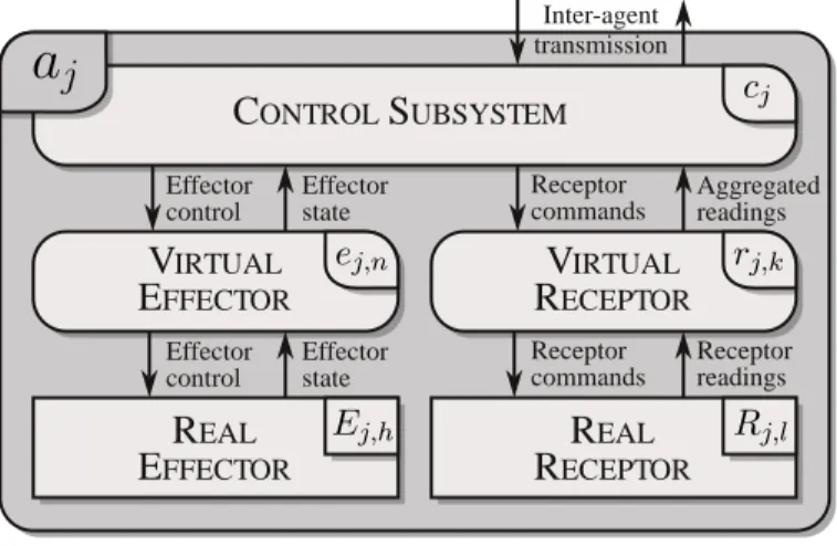
j,k Receptor commands Aggregated readings Effector control Effector state Receptor commands Receptor readings Effector state Effector controlFigure 1: Internal structure of an embodied agent
3. Agents
The RAPP system architecture is described in terms of agents. It uses two kinds of agents: embodied agents (fig. 1) and computational agents. The former are composed of: a control subsystem, one or more virtual effectors and zero or more virtual receptors. The control subsystem is responsible for the realisation of the task of the agent, while the virtual entities serve as device drivers for real effectors and real receptors – the hardware constituting the agent. The con-trolled hardware constitutes the body of the agent, hence an embodied agent. Computational agents, which do not posses effectors and receptors contain just the control subsystem. Thus embodied agents are a generalisation of computa-tional agents. So the activities of both kinds of agents are described in the same way. One robot can be controlled in conjunction by several agents.
The control subsystem as well as the virtual effectors and receptors are spec-ified in terms of FSM (Finite State Machine) defining sequences of behaviours [70, 71, 14]. The behaviours themselves are defined by transition functions and terminal conditions. Each transition function takes as arguments the input buffers to the subsystem and the contents of its internal memory and produces the values of output buffers and new values of the memory. This is done it-eratively at subsystem sampling rate until the terminal condition is fulfilled.
Terminal condition is a predicate taking as arguments the contents of input buffers and the memory. Iterations of the same transition function until the satisfaction of the terminal condition are called a behaviour. The FSM switch-ing its internal state switches the behaviours associated with those states, i.e. switches different transition functions.
4. RAPP system structure
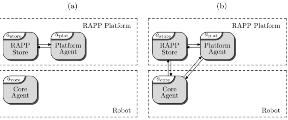
As the structure of a RAPP system changes over time, it is best presented as a sequence of system structures evolving in stages. The system is composed of a RAPP Platform and one or more robots. We assume that the RAPP Platform exists from the onset and robots know how to connect to it, but at initiation the RAPP Platform and the robot are separate entities (fig. 2a). To simplify the presentation a one robot structure will be considered here. Each robot is delivered with a Core Agent acore controlling it, thus at first it has to establish
communication with the RAPP Platform (fig. 2b).
(a) acore Core Agent aplat Platform Agent astore RAPP Store RAPP Platform Robot (b) acore Core Agent aplat Platform Agent astore RAPP Store RAPP Platform Robot
Figure 2: (a) RAPP system initial structure, (b) Connection of the Core Agent acoreto the
RAPP Platform aplat
Initially the RAPP Platform is composed of two agents: the Platform Agent aplatand the RAPP Store managed by the agent astore. When the robot user
commands it to perform a certain task the Core Agent acorecontacts the RAPP
task. The Core Agent acore installs the Dynamic Agent adyn on the robot
control computer (fig. 3a). At this stage the Dynamic Agent adyn assumes the
supervisory responsibilities over the system. The Core Agent acore becomes
the command server for the Dynamic Agent adyn. If the execution of the task
requires the Dynamic Agent adyn to directly access the services provided by the
Platform Agent aplat a connection between the two is established (fig. 3b).
(a) acore Core Agent adyn Dynamic Agent aplat Platform Agent astore RAPP Store RAPP Platform Robot (b) acore Core Agent adyn Dynamic Agent aplat Platform Agent astore RAPP Store RAPP Platform Robot
Figure 3: (a) Download and creation of the Dynamic Agent adyn, (b) Connection of the
Dynamic Agent adynto the Platform Agent aplat
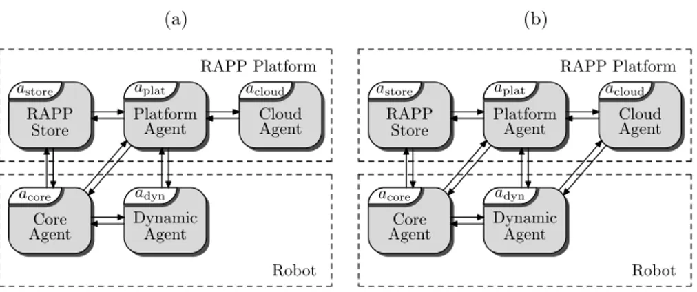
In specific cases the services required by the Dynamic Agent adyn from the
Platform Agent aplatmight form a complex sequence, or other specific services
might be required, which do not exist in the RAPP Platform. In such cases instead creating such services in the Dynamic Agent or invoking them directly by adynit is reasonable to create one or more Cloud Agents acloudin the RAPP
Platform (for the sake of simplicity of the presentation, in this paper it is as-sumed that just one such agent is created – this does not preclude the generality of the presentation as the interaction between the Dynamic Agent and the Cloud Agents is always the same and no direct interaction between Cloud Agents is asumed). The Cloud Agent will execute the required services autonomously and just provide the results to the Dynamic Agent adyn. Hence the Platform
Agent aplat upon a prompt from the Dynamic Agent adyn downloads the
re-quired Cloud Agent acloud from the RAPP Store astore, and initiates it in the
Agent adyn establishes a connection with it (fig. 4b). (a) acore Core Agent adyn Dynamic Agent aplat Platform Agent acloud Cloud Agent astore RAPP Store RAPP Platform Robot (b) acore Core Agent adyn Dynamic Agent aplat Platform Agent acloud Cloud Agent astore RAPP Store RAPP Platform Robot
Figure 4: (a) Creation of the Cloud Agent acloud, (b) Connection of the Dynamic Agent adyn
to the Cloud Agent acloud
This structure of the system persists until the task is finished. Once that happens, the Dynamic Agent adyn informs the Platform Agent aplat that the
Cloud Agent acloud is no longer necessary, thus it can be destroyed (situation
in fig. 3b is reestablished). It also informs the Core Agent acore that the task is
completed, thus the Dynamic Agent adyn can be destroyed. At this instant the
Core Agent acore ceases to be a command server for the Dynamic Agent adyn
and resumes its responsibilities as a supervisor of the system, thus the situation presented in fig. 2b is restituted. Now the cycle can be repeated upon a new command from the user. The RAPP system contains a repository of RApps (RAPP applications), which are the code for executing specific tasks that the user of a robot might require. It should be noted that RApps at execution time are equivalent to adyn. RApps are created by developers and stored in astore
internal memory (repository). Subsequently they are retrieved from the RAPP Store astore by the Core Agent acore.
5. Functions of the agents
The article [72] presents the distribution of system functions between par-ticular RAPP agents and theirs subsystems. Next, the functions of the agents
are presented, starting with the agents located in the robot controller and then those located in the RAPP Platform.
5.1. Core Agent
s1 Initialization
s2 Register with aplatand astore
s3 Listen to the user s4 Interpret the recorded command using aplat s5 Interpret command
s6 Load adynfrom astore
s7 Activate adyn
s8 Wait for command from adyn
s9 Execute command from adyn
s10 Destroy adyn s11 Unregister from aplat and astore s12 Finish s13 Record command s14
Inform the user
Isolated word Task finished Failed Abort Long command Failed
Figure 5: Graph of the FSM governing the behaviour of the Core Agent acore
Each robot included in the RAPP system contains a specific Core Agent acore
delivered by its manufacturer. This agent is responsible for communication with the user, downloading the Dynamic Agent adyn from the RAPP Store astoreand
providing to the Dynamic Agent the interface to the robot’s hardware – directly through its control subsystem and indirectly through its virtual effectors and receptors that are specific to particular robots. The activities of the Core Agent acoreare described by the FSM in fig. 5. In reality this are the activities of the
this subsection, the other subsystems will not be addressed, the agent and its control subsystem will not be distinguished. Computational agents contain only their control subsystems, thus this distinction in that case is not necessary as well. After initialization acore registers itself with the RAPP Platform by
con-necting to the Platform Agent aplatand the RAPP Store astoreand subsequently
starts to listen to the user’s commands, which can be expressed in one of the two forms: as an isolated keyword or a long command. In each of those cases interpretation is different. The isolated keywords are known to acore and so it
decides which Dynamic Agent should be downloaded from the store in response. The long commands are only recorded by acore and then sent for interpretation
to aplat. The Platform Agent aplat decides which Dynamic Agent should be
downloaded by acore. Successfully interpreted user’s command results in
down-loading and activating the adequate Dynamic Agent adyn. Herein, for brevity,
different Dynamic Agents are not distinguished by an additional subscript. If interpretation of the command fails, acore returns to listening to the user. After
adynhas been activated, acorewaits for its commands and subsequently executes
them. Once adynhas completed its task it notifies acore about that. This results
in acore destroying adyn. Subsequently acore goes back to listening to the user’s
commands.
The Core Agent acoreacts as a service provider for the Dynamic Agent adyn.
Whenever adyn needs the resources of the robot, i.e. its effectors or receptors, to
carry out the task it must request a service from acore, which waits for commands
in the FSM state represented by the graph node s8(fig. 5). Each such service is represented as a sub-FSM symbolised by the double encircled node s9. It should be noted that all real-time critical services are provided by fig. 5 in its state s9,
so the delays introduced by the communication with adyn and acloud may slow
down the activities of the system as a whole, but will not affect the real-time performance of the robot hardware.
5.2. Dynamic Agent
The Dynamic Agent adyn is responsible for the execution of the task
com-manded by the user and is dynamically initiated on the robot with the start of the task. The graph of the FSM representing the required sequence of be-haviours depends on this task. The Dynamic Agent communicates with other agents using a standardized API. The Core Agent has to be organized in such a way as to execute all of the API functions invoked by all the Dynamic Agents, hence the detailed implementation of the API functions in the Core Agent as well as the robot hardware do not affect the task formulation in the Dynamic Agent.
The Dynamic Agent FSM is designed by the RApp provider. An exemplary Dynamic Agent adyn responsible for the execution of a hazard detection task
will be presented in section 7. Its graph is presented in fig. 16 in that section.
5.3. Platform Agent
The Platform Agent aplatpresents its computational capabilities to the Core
Agent acoreand the Dynamic Agent adynas a set of services that can be grouped
into few general subsets. Communication services currently enable the robot to perform automated speech recognition (using either Sphinx [73] or Google libraries), speech synthesis as well as sending and receiving e-mail messages [74]. Those services can be used directly by the Core Agent to recognize the command produced by the user, when the robot is not capable of recognising the command using only the on-board skills. Another large subset of services is responsible for image processing and object detection. To recognize people, there are human detection as well as face detection and recognition services. Other services enable scene recognition and object detection. The light checking and door-opening estimator makes it possible to create applications automatically assuring user safety. The navigation subset contains map management services and enables global localization (initially based on QR codes and currently doing without them). Using global obstacle map, the path between two points can be planned. A set of information services (geolocalization, news and weather) and ontology
(Knowrob) supplements the platform capabilities. Fig. 6 presents the general structure of the FSM governing the agent aplat.
s1 Wait for service request
from adynor acore
s2 Provide the service requested
by adynor acore
Figure 6: Graph of the FSM governing the behaviour of the Platform Agent aplat
5.4. Cloud Agent
A Cloud Agent must be compatible with its respective Dynamic Agent – it is created by the RApp developer as a part of a particular application. It is meant to be available only to this one application, and its lifetime is similar to the lifetime of the Dynamic Agent, i.e. when the Dynamic Agent is launched, the corresponding Cloud Agent is launched too, and both terminate their existence at the same time.
The Cloud Agent is responsible for the execution of tasks, that are too computationally expensive to run them on the robot controller, yet not general enough to be implemented as platform services. The Cloud Agent can be also used as a macro-service, calling multiple platform services and returning the final result to the Dynamic Agent, allowing it to run other tasks in parallel without time-consuming back-and-forth communication and dealing with intermediate service results.
5.5. RAPP Store
The RAPP Store caters to: robot owners, RApp developers and the Core Agents controlling the robots. Every new robot owner registers with astore.
The Core Agents register with astore and aplat and thus gain access to the
RAPP infrastructure. From the point of view of the Core Agent acore the
most important service provided by astore is the ability to download RApps,
also responsible for providing services to the RApp developers for building and submitting RApps. Its obvious responsibility is storing RApps. The RApps are hosted in the form of precompiled binaries of Dynamic Agents represented by adyn.
6. Implementation
Implementation of the RAPP infrastructure follows the agent-structure, de-picted in fig. 4b. As the RAPP system is rather complex, an in-depth description of the implementation of every single component is beyond the scope of this pa-per, for obvious reasons – rather the general idea and the main concepts will be explained. This section is organized in top-down manner, describing top-level modules and communication between them first and then going deeper into each submodule and service.
6.1. Communication between agents
Figure 7 presents the same blocks as fig. 4b, however from a different perspec-tive, focusing on the communication between the top-level entities, i.e. agents. Apart from the Dynamic Agent, every other module exposes its services (or, in general, capabilities) to the public. To make possible the use of them by the others, every agent has an API prepared for that purpose.
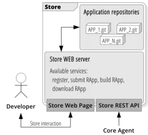
6.2. RAPP Store
The RAPP Store exposes just a few services to be used mostly by the Core Agent. Those are available using the REST API (HTTP request-response). It enables the listing of available applications, searching for a specific one, gath-ering information about the selected application and downloading a compiled package to run as a Dynamic Agent. Internal structure of the Store is presented in fig. 8.
The RAPP Store is responsible for the whole process of application prepa-ration. Every developer can create many git repositories, each containing the
RAPP Improvement Center (RIC)
ROSbridge Service req/resp
Store Agent Platform Agent Cloud Agents Ecosystem
DB
Deploy Cloud Agent
Store WEB server
Store REST API
Core Agent Download
application Dynamic Agent
Launch Dynamic Agent Launch Cloud Agent Call Platform
services
Call Cloud Agent services
Call Core Agent services Application
repositories
Robot FSM Core Robot
services Robot API
Platform WEB server
Platform WEB API
Cloud Agent Manager Cloud Agent #1 Cloud Agent #1 Cloud Agent #1 Cloud Agent #1
Rapp Client Libraries (C++/JS/Python) Launch
control Request package
Figure 7: Overall architecture of the RAPP infrastructure
source codes of one RApp. When the code is ready, the programmer can re-lease his/her application for use by the selected robotic platforms. The RAPP Store is responsible for RApp compilation (if necessary) and packaging. There is a separate virtual machine for each available robot. It is used as a build server. The whole interaction between the developers and the Store is possible using web interface.
6.3. RAPP Platform
The RAPP Platform [75] provides its services as web services, implemented using HOP [76, 77]. Some robots such as NAO can recognise only a limited set of commands. Others, such as the Elektron mobile robot do not have the recog-nition capability at all. The client uses the Platform API (available for Python,
Store Developer Application repositories APP_1.git APP_N.git APP_2.git Store interaction Core Agent
Store WEB server Available services:
register, submit RApp, build RApp, download RApp
Store REST API Store Web Page
Figure 8: Internal structure of the RAPP Store
C++ and Java Script) to invoke Platform services, thus releasing the applica-tion developer from the tedious task of managing the network communicaapplica-tion and making the platform services almost as easy to use as local functions.
The Platform API, among others, is responsible for authentication – each call to the platform is supplemented with a user token. Based on it the user status is ascertained (e.g. it is verified whether the selected service is available for the given user or not) as well as adequate data storage is selected (e.g. each user has a personal set of face images to be recognised, maps for navigation etc.).
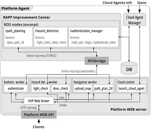
If the service is rudimentary, such as file upload or database query, it can be implemented directly in HOP. More complex algorithms need the RAPP Improvement Center (RIC), which uses ROS [78, 79]. Each node provides one or more services, which are called from HOP using rosbridge websockets server [80]. ROS enables many possibilities of node implementation. The majority of the RAPP system modules is implemented using either C++ or Python. Internally, each ROS node runs multiple processing threads, so that it can process calls from many clients simultaneously. Taking into account how ROS threads are handled, it becomes apparent that ROS nodes that are purely functional (i.e.
Platform Agent
DB
Platform WEB server RAPP Improvement Center
Platform WEB API
ROSbridge
HOP Web Broker
authenticate light_check door_check upload_map path_plan_2d
Navigation worker Hazard det. worker
Authent. worker
exec invoke HTTP req/resp
Service req/resp (websockets) /authentication_manager Services:
/add_user, /login, /authenticate_token ROS nodes (excerpt)
/hazard_detection Services: /light_check, /door_check /path_planning Services: /plan_path_2d
Service req/resp (TCPROS)
Clients Cloud Agent Manager Cloud control launch_cloud_agent Store Cloud Agents infr.
Figure 9: Internal structure of the RAPP Platform Agent
do not posses an internal state or a back-end procedure) have no problems with simultaneous calls. On the other hand, nodes such as the Knowrob Wrapper or the Sphinx4 ASR system, which depend on the deployment of other packages, need special handling. In the case of RAPP Platform, it was decided that only the Sphinx4 ASR ROS node is in need of such service handling, since this will be the most frequently invoked one. The assumed solution involves the creation of several back-end Sphinx4 processes, along with a handler, which accepts the requests and decides which process should serve them. At any time, the handler monitors the processes to keep track which of them are occupied and what are their current configurations. Thus if, for example, a speech recognition invo-cation occurs with a specific configuration, the pool of unoccupied processes is tested to find out whether any of them is already configured as requested. If
this is the case, the handler proceeds directly to the speech recognition process, or if not, the handler selects a random unoccupied process and performs both configuration and recognition. This approach was chosen, because the configu-ration process is quite time consuming and requires significant resources, thus it should be avoided whenever possible.
The RAPP Platform contains the RAPP database which can be accessed by:
• the RAPP Store, to keep track of the user accounts and the submit-ted/downloaded applications and
• the RAPP Improvement Centre to provide machine learning/statistical data gathering and data acquisition – this is done via a ROS MySQL wrapper, providing interfaces to all the nodes in need of stored data.
6.4. Core agent 6.4.1. Robots
As it has been said in section 5.1, the Core Agents implementation is de-pendent on the hardware it controls. On the other hand, the set of functions available for the Dynamic Agents to call must be known in advance and, as much as possible, independent on the particular robot. In social robotics, in particular in tasks for which RAPP is designed, those functions can be divided into three main groups: communication, vision and navigation skills.
Communication is required by the Core Agents main automaton – interaction with the user is done using spoken commands and synthesized replies. Thus, at least two skills should be present: say – to synthesize a sentence; and word spotting – listen to and recognize words. Other useful functions are capturing and playing back audio files.
As the sight is one of the most important human senses, and one giving the most information, also robots vision services plays a key role in whole system design. Main function in this group is responsible for capturing pictures, and a few helper functions should also be created for changing camera parameters,
reading current settings and calibration etc. Robot should also be able to look at given point in space, to look for specified object for example.
Last, but not least, in order to cooperate with people and to be able to move around in a home, the robot should possess some kind of navigation capabilities. Those should permit, at least, motion with with a predetermined speed, self-localization relative to the starting point (based on odometry) and motion to a specified point (with respect to a local coordinate frame).
Ultrasonic sensors Upper camera Legs Touch sensors 58 c m Lower camera Arms
Figure 10: NAO robot: description of relevant components
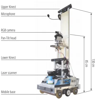
Those skills can be implemented in many robots. To show versatility of the proposed solution two different robots have been included into the RAPP system: NAO humanoid robot (fig. 10) and Elektron mobile robot (fig. 11). Those robots are very different in their capabilities. NAO is a humanoid – this implies that it can execute holonomic motion, i.e. walk in any direction; while Elektron having wheels and a differential drive is non-holonomic. NAO is equipped with two medium quality cameras on a moving head, while Elektron has one high quality moving camera and two fixed Kinect sensors. Table 1 compares the relevant components of each robot.
Upper Kinect Lower Kinect RGB camera Pan-Tilt head Laser scanner Mobile base Microphone 130 cm 85 c m
Figure 11: Elektron robot: description of relevant components
6.4.2. Implementation details
Implementation of the Core Agent is composed of two main parts (fig. 12). First, control subsystem, managing the FSM (fig. 5) is almost independent of a particular robot. The control subsystem is written in the C++ programming language, as a ROS node, thus any robot which is ROS-enabled and has basic abilities record and playback sound. If the robot has no built-in capabilities to recognize spoken text and transform text to speech (as is the case of the Elektron robot), the Core Agent can send the recording to the Platform Agent for recognition.
The FSM, after successful recognition of the user command, downloads a compressed archived file with the selected RApp and unpacks it. As the Dynamic Agent can be developed in one of three possible languages: C++,
Table 1: Comparison of components of the robots
Function NAO Elektron
Say Internal sentence synthesizer N/A Word spotting Internal ASR service N/A Recording Four microphones One microphone
Playback Speakers Speakers
Capture image Two RGB cameras 1280x960px, wide angle
One RGB camera 1280x1024px, narrow angle Two Kinect RGB-D sensors
640x480px, wide angle Mobility Two legs, holonomic movement Differential drive, non holonomic
Speed ?? Up to 0.25m/s
Python or JavaScript, the RApp developer has to prepare the deployment script, responsible for correct start of the application (in the simplest case just calling the executable). This script is initiated by the Core Agent as a new process (fork–exec procedure). Task is treated as finished when this process dies – the Core Agent monitors its state and detects this event.
Download application Launch Dynamic Agent Launch
Cloud Agent CloudAgent
service invocation Core Agent Robot FSM Core Services move_to, take_predefined_pose, look_at, take_picture,
say, word_spotting, ... Robot API
Platform service invocation Robot service invocation Dynamic Agent
robot_api client library
(C++/JS/Python)
platform_api client library
(C++/JS/Python)
cloud_agent client library
(up to application programmer)
cloud_agent control library
(C++/JS/Python)
Underlying services, provided by the two aforementioned robots, are imple-mented as ROS nodes. In the case of the NAO robot the virtual effectors are: ecore,body that is responsible for the motion of all of its limbs and the head, and ecore,ls that governs the loudspeakers and executes text to speech transforma-tion. The NAO virtual receptors are: rcore,cam that is responsible for acquiring images by the camera, rcore,sonarthat detects obstacles using ultrasonic sensors, rcore,touchthat detects obstacles using micro-switches located in the feet of the robot, and rcore,mic that detects sound using microphones and recognizes words. All those virtual effectors and receptors are commanded by the control subsys-tem ccore (fig. 13). Those subsystems are implemented in Python. The virtual effectors and receptors contact the hardware via the NAOqi client library (pro-vided by the robot manufacturer), thus this library is treated as a part of real effectors and receptors.
Core Agent (NAO) ccore
ecore,body
Upper camera
Body + head Loudspeakers cameraLower sensorsSonar sensorsTouch Microphone
ecore,ls rcore,cam rcore,sonar rcore,touch rcore,mic
Robot API
Figure 13: Core Agent of NAO robot
The virtual effectors of the Elektron robot are: ecore,base that is responsible for the motion of the mobile base, ecore,headcontrolling the movements of camera supporting head and ecore,ls that governs the loudspeakers. Virtual receptors are responsible for gathering images from multiple cameras: rcore,rgb from RGB camera, rcore,kin_topand rcore,kin_botfrom Kinect sensors. Laser scanner is man-aged by rcore,laser, and rcore,mic records sounds using microphone (fig. 14). The Elektron robot software was implemented in C++ as a set of ROS nodes.
Core Agent (Elektron) ccore
ecore,body
Mobile base Loudspeakers Lower
Kinect Microphone
Laser scanner ecore,ls rcore,kin_bot rcore,mic rcore,laser
Robot API
ecore,head
Head Upper
Kinect rcore,kin_top
Figure 14: Core Agent of Elektron robot
6.5. Cloud agents
Cloud Agent part of the application is uploaded by the developer to the RAPP Store along with the Dynamic Agent. The communication with the Cloud Agents has two aspects. First, there is an API for spawning and con-trolling the execution of the Cloud Agents. The Dynamic Agent, using those functions, can command the Platform Agent to launch a specific Cloud Agent. When requested, the Platform Agent first checks in the Store whether the de-sired package is available, then downloads it and builds using scripts provided with the package. After successful build, the created application is deployed on a new Docker container (lightweight software virtualization [81]) instance and the identifier of the created Cloud Agent is returned to the calling Dy-namic Agent [82]. This identifier is then used when calling services provided by the Cloud Agent. Those services form the second part of the Cloud Agent communication mechanism, and are strictly dependent on the application, i.e, RApp.
7. Experiments
Forgetfulness is a typical problem for elderly people suffering from MCI. For instance, leaving the house they tend to forget shutting windows, balcony doors, leaving open refrigerator doors or lights switched on. Detection of such
hazards can be handled by equipping the home with a multitude of sensors, however elderly people usually dislike any modifications to their homes and subsequent maintenance of the resulting system. Thus a different remedy can be recommended. A robot can detect all potential risks by exploring the home. In our experiments two different robotic platforms have been employed to carry out this task, the NAO humanoid robot and Elektron wheeled mobile robot (fig. 15). Besides the locomotion mechanism these robots differ in their onboard sensory systems.
(a) (b)
Figure 15: Robots performing hazard detection: (a) NAO humanoid robot, (b) six-wheel Elektron robot
The scenario is the following. Upon request from the user or executing a scheduled task the robot searches the house, locating all hazards and subse-quently reports them to the user, ensuring his or her safety, thus supporting independent living. To perform this task the robot control system (the Core Agent namely) downloads and initiates an appropriate RApp from the RAPP Store. This RApp is installed in the robot control system in a form of a Dy-namic Agent, thus the Core Agent and the DyDy-namic Agent share the control computer.
The graph of the FSM governing the actions of the Dynamic Agent realising the hazard detection task is presented in fig 16. To execute the hazard detection task, first the robot has to get the map of the environment and the associated list
s1 Get the map and list of hazards
from the RAPP Platform s2 Self-localization
s3 Send the current robot pose
to the RAPP Platform s4 Retrive the path from
the RAPP Platform s5 Execute the path
s6 Notify the Core Agent
about the detected hazards s7 Notify the Core Agent
about the task termination
Figure 16: Graph of the FSM governing the behaviour of the Dynamic Agent adynrealising
the hazard detection task
of possible hazard locations. This is done by the behaviour associated with the FSM state (graph node) s1. Next, the robot must localize itself on the map with
respect to the global coordinate frame using a self-localization strategy based on visual landmarks. This is done by a subFSM, hence the double encirclement of the node s2. Self-localization enables the Dynamic Agent to obtain the robot global pose, which is required in the following stages of the RApp execution. Once the robot global pose is computed, the Dynamic Agent sends this pose and the requested hazard pose to the RAPP Platform agent to gather a collision-free path to the pose suitable to analyse the particular hazard. This is done by the behaviours associated with states s3and s4.
Once the path is obtained its execution commences. The robot moves to the way-points located along the path; however not in each of them it has to look for hazards. At each way-point the robot has to self-localize. All this is done by a subFSM symbolised by s5. The performed experiments show that the robot localizes itself with good accuracy (for the NAO robot the localization error is ±10 cm and for the Elektron is ±7 cm. This enables better tracking of
the desired path. The robot follows the desired path with adequate accuracy. The maximum path tracking error is 15 cm for the Elektron robot and 20 cm for the NAO. This is a satisfactory result for such a simple robot. In general, path execution strongly depends on the robot effectors and sensors, and its Core Agent abilities.
Hazard detection depends on the type of hazard and on the object it is associated with. We use monocular vision to collect hazard information. In locations where potential hazards may occur, the Dynamic Agent requests the Core Agent to orient the robot’s camera to point at the possible hazard point, e.g. lamp, door. In the case of open-doors detection the state of the doors is based on image analysis process that starts with looking for all sufficiently long linear segments, that are further categorized into vertical and horizontal ones (white or gray as shown in fig. 17). From the horizontal lines, two are selected, that form wall/floor and door/floor intersections. Those are selected as the longest lines with an inclination closest to the horizontal line. The algorithm is prepared in such a way, that the found lines are always localized on opposite sides of the picture (left and right). Finally the door-opening angle estimation is made by simply calculating the angle between the two found lines (marked in black in the pictures in fig. 17).
(a) (b)
Figure 17: Sample images for door-opening angle estimation
robot moves its camera to look at the place that the lamp is located in. Then an image is captured and image processing is performed to detect an intensive light. Light status is checked by analyzing the picture taken with low exposure, while looking directly at the light source (as presented in fig. 18).
(a) (b)
Figure 18: Sample images for light checking
Light level is calculated as a ratio between the average intensity of the cen-tral rectangle in the image and the average intensity in surrounding rectangles. Size of the rectangles is selected in such a way, that the central one is the most important, while surroundings form a rough approximation of a circle. The re-sult is normalized to the range [0..100], where 0 means that the light is probably turned off and 100 maps to the light turned on without doubt.
Next the Core Agent is notified about the detected hazards, so that it can report them to the user – the behaviour associated with state s6 is responsible for that. Finally the Dynamic Agent informs the Core Agent that the task is done, so that it can destroy adyn – this is done by the behaviour associated with
8. Conclusions
Besides the hazard detection task, which was tested both on the NAO and Elektron robots, the RAPP system has been tested on several other benchmark examples, e.g.: voice e-mail via NAO [74], [83], NAO the weather reporter, news explorer via NAO, playing cognitive games with NAO. The multiplicity of both the robots used and the tasks executed convince that the assumed control architecture is fully functional. The proposed architecture solves the problem of high computational requirements versus limited resources.
Acknowledgement
This work is funded by the EU Commission within the FP7 Collaborative Project RAPP (Grant No 610947). Moreover it is supported by the Polish Min-istry for Science and Higher Education scientific research funds for the years 2014–2016 granted for the realisation of co-financed international project.
[1] W. Lutz, W. Sanderson, S. Scherbov, The coming acceleration of global population ageing, Nature 451(7179) (2008) 716—-719. doi:10.1038/ nature06516.
[2] S. Reppou, G. Karagiannis, Social inclusion with robots: A RAPP case study using NAO for technology illiterate elderly at ormylia foundation, in: R. Szewczyk, C. Zieliński, M. Kaliczyńska (Eds.), Progress in Automation, Robotics and Measuring Techniques. Vol. 2 Robotics., Vol. 351 of Advances in Intelligent Systems and Computing (AISC), Springer, 2015, pp. 233–241. [3] S. Reppou, G. Karagiannis, E. Tsardoulias, A. Kintsakis, A. Symeoni-dis, P. Mitkas, F. Psomopoulos, C. Zieliński, V. Prunet, M. Iturburu, S. Arampatzis, RAPP: A robotic-oriented ecosystem for delivering smart user empowering applications for older people, International Journal of So-cial Roboticsdoi:10.1007/s12369-016-0361-z.
[4] A. Manzi, L. Fiorini, R. Esposito, M. Bonaccorsi, I. Mannari, P. Dario, F. Cavallo, Design of a cloud robotic system to support senior citi-zens: the kubo experience, Autonomous Robots (2016) 1–11doi:10.1007/ s10514-016-9569-x.
URL http://dx.doi.org/10.1007/s10514-016-9569-x
[5] M. Bonaccorsi, L. Fiorini, S. Sathyakeerthy, A. Saffiotti, F. Cavallo, P. Dario, Design of cloud robotic services for senior citizens to improve independent living in multiple environments., in: Intelligenza Artificiale, Vol. 9, 2015, pp. 63–72.
[6] P. Deegan, R. Grupen, A. Hanson, E. Horrell, S. Ou, E. Riseman, S. Sen, B. Thibodeau, A. Williams, D. Xie, Mobile manipulators for assisted living in residential settings, Autonomous Robots 24 (2) (2008) 179–192. doi: 10.1007/s10514-007-9061-8.
URL http://dx.doi.org/10.1007/s10514-007-9061-8
[7] J. Kędzierski, P. Kaczmarek, M. Dziergwa, K. Tchoń, Design for a robotic companion, International Journal of Humanoid Robotics 12 (2015) 1–24. doi:10.1142/S0219843615500073.
[8] B. Görer, A. A. Salah, H. L. Akın, An autonomous robotic exercise tutor for elderly people, Autonomous Robots (2016) 1–22doi:10.1007/ s10514-016-9598-5.
URL http://dx.doi.org/10.1007/s10514-016-9598-5
[9] E. G. Tsardoulias, A. M. Kintsakis, K. Panayiotou, A. G. Thal-las, S. E. Reppou, G. G. Karagiannis, M. Iturburu, S. Aram-patzis, C. Zieliński, V. Prunet, F. E. Psomopoulos, A. L. Syme-onidis, P. A. Mitkas, Towards an integrated robotics architecture for social inclusion–the rapp paradigm, Cognitive Systems Re-searchdoi:http://dx.doi.org/10.1016/j.cogsys.2016.08.004. URL http://www.sciencedirect.com/science/article/pii/ S1389041716300535
[10] F. Psomopoulos, E. Tsardoulias, A. Giokas, C. Zieliński, V. Prunet, I. Trochidis, D. Daney, M. Serrano, L. Courtes, S. Arampatzis, P. Mitkas, Rapp system architecture, in: IROS 2014 – Assistance and Service Robotics in a Human Environment, Workshop in conjunction with IEEE/RSJ Inter-national Conference on Intelligent Robots and Systems, Chicago, Illinois, September 14, 2014, pp. 14–18.
[11] D. M. Lyons, M. A. Arbib, A formal model of computation for sensory-based robotics, IEEE Transactions on Robotics and Automation 5 (3) (1989) 280–293.
[12] D. M. Lyons, Prerational intelligence, Vol. 2: Adaptive behavior and intel-ligent systems without symbols and logic of Studies in cognitive systems, Kluwer Academic, 2001, Ch. A Schema-Theory Approach to Specifying and Analysing the Behavior of Robotic Systems, pp. 51–70.
[13] C. Zieliński, A Quasi-Formal Approach to Structuring Multi-Robot Sys-tem Controllers, in: Second International Workshop on Robot Motion and Control, RoMoCo’01, 2001, pp. 121–128.
[14] C. Zieliński, T. Kornuta, Diagnostic requirements in multi-robot systems, in: Intelligent Systems in Technical and Medical Diagnostics, Vol. 230, Springer, 2014, pp. 345–356. doi:10.1007/978-3-642-39881-0_29. URL http://robotyka.ia.pw.edu.pl/twiki/pub/Publications/ AllArticles/2014_dps_diagnostics.pdf
[15] C. Armbrust, L. Kiekbusch, T. Ropertz, K. Berns, Soft robot control with a behaviour-based architecture, in: Soft Robotics, Springer, 2015, pp. 81–91. [16] L. Kiekbusch, C. Armbrust, K. Berns, Formal verification of behaviour networks including sensor failures, Robotics and Autonomous Systems 74 (2015) 331–339.
networks including hardware failures, in: Intelligent Autonomous Systems 13, Springer, 2016, pp. 1571–1582.
[18] D. Kortenkamp, R. Simmons, Robotic systems architectures and program-ming, in: O. Khatib, B. Siciliano (Eds.), Springer Handbook of Robotics, Springer, 2008, pp. 187–206.
[19] E. Coste-Maniere, R. Simmons, Architecture, the backbone of robotic systems, in: Robotics and Automation, 2000. Proceedings. ICRA ’00. IEEE International Conference on, Vol. 1, 2000, pp. 67–72 vol.1. doi: 10.1109/ROBOT.2000.844041.
[20] M. J. Matarić, F. Michaud, The Handbook of Robotics, Springer, 2008, Ch. Behavior-Based Systems, pp. 891–909.
[21] Z. Bulter, A. Rizzi, Distributed and cellular robots, in: O. Khatib, B. Sicil-iano (Eds.), Springer Handbook of Robotics, Springer, 2008, pp. 911–920. [22] L. E. Parker, Multiple mobile robot systems, in: O. Khatib, B. Siciliano
(Eds.), Springer Handbook of Robotics, Springer, 2008, pp. 921–941. [23] M. Yim, W.-M. Shen, B. Salemi, daniela Rus, M. Moll, hod Lipson,
E. Klavins, G. S. Chirikjian, Modular self-reconfigurable robot systems [grand challenges of robotics], IEEE Robotics & Automation Magazine 14 (1) (2007) 43–52.
[24] M. J. Matarić, Issues and approaches in the design of collective au-tonomous agents, Robotics and Auau-tonomous Systems 16 (2) (1995) 321 – 331. doi:http://dx.doi.org/10.1016/0921-8890(95)00053-4.
URL http://www.sciencedirect.com/science/article/pii/ 0921889095000534
[25] A. Farinelli, L. Iocchi, D. Nardi, Multirobot systems: a classification fo-cused on coordination, IEEE Transactions on Systems, Man, and Cybernet-ics, Part B (Cybernetics) 34 (5) (2004) 2015–2028. doi:10.1109/TSMCB. 2004.832155.
[26] G. Dudek, M. R. M. Jenkin, E. Milios, D. Wilkes, A taxonomy for multi-agent robotics, Autonomous Robots 3 (4) (1996) 375–397. doi:10.1007/ BF00240651.
URL http://dx.doi.org/10.1007/BF00240651
[27] R. Doriya, S. Mishra, S. Gupta, A brief survey and analysis of multi-robot communication and coordination, in: Computing, Communication Automation (ICCCA), 2015 International Conference on, 2015, pp. 1014– 1021. doi:10.1109/CCAA.2015.7148524.
[28] A. Chibani, Y. Amirat, S. Mohammed, E. Matson, N. Hagita, M. Barreto, Ubiquitous robotics: Recent challenges and future trends, Robotics and Autonomous Systems 61 (11) (2013) 1162 – 1172. doi:http://dx.doi. org/10.1016/j.robot.2013.04.003.
[29] C. Zieliński, Reaction based robot control, Mechatronics 4 (8) (1994) 843– 860.
[30] C. Zieliński, Motion generators in MRROC++ based robot controller, in: G. Bianchi, J.-P. Guinot, C. Rzymkowski (Eds.), 14th CISM–IFToMM Symposium on Robotics, Ro.Man.Sy’02, Udine, Italy, CISM Courses and Lectures no.438, Springer, Wien, New York, 2002, pp. 299–306.
URL http://www.ia.pw.edu.pl/~zielinsk/romansy2.pdf
[31] C. Zieliński, T. Winiarski, Motion generation in the MRROC++ robot programming framework, International Journal of Robotics Research 29 (4) (2010) 386–413. doi:10.1177/0278364909348761.
[32] A. Dietrich, T. Wimbock, A. Albu-Schaffer, G. Hirzinger, Reactive whole-body control: Dynamic mobile manipulation using a large number of ac-tuated degrees of freedom, IEEE Robotics Automation Magazine 19 (2) (2012) 20–33. doi:10.1109/MRA.2012.2191432.
manipulation, Robotica (2014) 1–16doi:10.1017/S0263574713000763. URL http://journals.cambridge.org/article_S0263574713000763 [34] D. Leidner, A. Dietrich, M. Beetz, A. Albu-Schäffer, Knowledge-enabled
parameterization of whole-body control strategies for compliant service robots, Autonomous Robots 40 (3) (2016) 519–536. doi:10.1007/ s10514-015-9523-3.
URL http://dx.doi.org/10.1007/s10514-015-9523-3
[35] M. Rubenstein, A. Cornejo, R. Nagpal, Programmable self-assembly in a thousand-robot swarm, Science 345 (6198) (2014) 795–799. doi:10.1126/ science.1254295.
URL http://science.sciencemag.org/content/345/6198/795
[36] C. Zieliński, P. Trojanek, Stigmergic cooperation of autonomous robots, Journal of Mechanism and Machine Theory 44 (2009) 656–670.
[37] R. Tron, J. Thomas, G. Loianno, J. Polin, V. Kumar, K. Daniilidis, Vision-based formation control of aerial vehicles, in: Robotics Science and Systems (RSS), Distributed Control and Estimation for Robotic Vehicle Networks, Bekeley, CA, USA, 2014.
URL https://drive.google.com/file/d/ 0Bzvnra8UKhpcZVptc1dLSWRjU1IwODFwd2ZOcWQzSHhkLWNB/edit
[38] L. Parker, ALLIANCE: An architecture for fault tolerant multirobot co-operation, IEEE Transactions on Robotics and Automation 14 (2) (1998) 220–240.
[39] C. Zieliński, W. Kasprzak, T. Kornuta, W. Szynkiewicz, P. Trojanek, M. Walęcki, T. Winiarski, T. Zielińska, Control and programming of a multi-robot-based reconfigurable fixture, Industrial Robot: An Interna-tional Journal 40 (4) (2013) 329–336. doi:10.1108/01439911311320831. [40] R. Simmons, S. Singh, D. Hershberger, J. Ramos, T. Smith, First Results