Publisher’s version / Version de l'éditeur:
Engineering Construction and Architectural Management, 16, 4, pp. 376-391, 2009-07-01
READ THESE TERMS AND CONDITIONS CAREFULLY BEFORE USING THIS WEBSITE.
https://nrc-publications.canada.ca/eng/copyright
Vous avez des questions? Nous pouvons vous aider. Pour communiquer directement avec un auteur, consultez la première page de la revue dans laquelle son article a été publié afin de trouver ses coordonnées. Si vous n’arrivez pas à les repérer, communiquez avec nous à [email protected].
Questions? Contact the NRC Publications Archive team at
[email protected]. If you wish to email the authors directly, please see the first page of the publication for their contact information.
NRC Publications Archive
Archives des publications du CNRC
This publication could be one of several versions: author’s original, accepted manuscript or the publisher’s version. / La version de cette publication peut être l’une des suivantes : la version prépublication de l’auteur, la version acceptée du manuscrit ou la version de l’éditeur.
For the publisher’s version, please access the DOI link below./ Pour consulter la version de l’éditeur, utilisez le lien DOI ci-dessous.
https://doi.org/10.1108/09699980910970851
Access and use of this website and the material on it are subject to the Terms and Conditions set forth at
Integrating numerical tools in underground construction process
Attar, A.; Boudjakdji, M. A.; Bhuiyan, N.; Grine, K.; Kenai, S.; Aoubed, A.
https://publications-cnrc.canada.ca/fra/droits
L’accès à ce site Web et l’utilisation de son contenu sont assujettis aux conditions présentées dans le site LISEZ CES CONDITIONS ATTENTIVEMENT AVANT D’UTILISER CE SITE WEB.
NRC Publications Record / Notice d'Archives des publications de CNRC:
https://nrc-publications.canada.ca/eng/view/object/?id=aa9292e6-e340-4e57-ba17-48ea6d4f77bc https://publications-cnrc.canada.ca/fra/voir/objet/?id=aa9292e6-e340-4e57-ba17-48ea6d4f77bc
http://www.nrc-cnrc.gc.ca/irc
I nt e gra t ing num e ric a l t ools in unde rground c onst ruc t ion proc e ss
N R C C - 5 1 2 6 3
A t t a r , A . ; B o u d j a k d j i , M . A . ; B h u i y a n , N . ; G r i n e , K . ; K e n a i , S . ; A o u b e d , A . u t h o r
J u l y 2 0 0 9
A version of this document is published in / Une version de ce document se trouve dans: Engineering Construction and Architectural Management, 16, (4), 2009, pp. 376-391, DOI: 10.1108/09699980910970851
The material in this document is covered by the provisions of the Copyright Act, by Canadian laws, policies, regulations and international agreements. Such provisions serve to identify the information source and, in specific instances, to prohibit reproduction of materials without written permission. For more information visit http://laws.justice.gc.ca/en/showtdm/cs/C-42
Les renseignements dans ce document sont protégés par la Loi sur le droit d'auteur, par les lois, les politiques et les règlements du Canada et des accords internationaux. Ces dispositions permettent d'identifier la source de l'information et, dans certains cas, d'interdire la copie de documents sans permission écrite. Pour obtenir de plus amples renseignements : http://lois.justice.gc.ca/fr/showtdm/cs/C-42
Integrating Numerical Tools in Underground Construction Process
Ahmed Attar
1, Mohamed Amine Boudjakdji
1, Nadia Bhuiyan
2, Khaled Grine
1,
Said Kenai
1and Ali Aoubed
1(1): University Saâd Dahlab-Blida, Faculty of Engineering, Algeria
(2): Concordia University, Mechanical and Industrial Department, Montréal, Canada
Abstract
Purpose – In Algeria, the time frame for the execution of a construction project is rarely respected because of
organizational problems and uncertainties encountered while the execution is underway. A case study on the construction of a metro station is used as a pilot project to show the effectiveness of replacing traditional construction processes by more innovative procedures.
Design/methodology/approach – Concurrent Engineering (CE) is applied to optimize the execution time of the
underground structure. A numerical simulation is integrated into the construction process in order to update design parameters with real site conditions observed during the construction process.
Findings – The results show that the implementation of CE is efficient in reducing the completion time, with an
18% reduction observed in this case study. A cost reduction of 20% on the steel frame support and a total cost reduction of 3% were obtained.
Research limitations/implications – The study demonstrates that the application of CE methods can be quite
valuable in large, complex construction projects. Vulgarizing it as “the solution” to adjust time frame delay, control quality and cost, might be an issue for local construction enterprises in Algeria.
Originality/value – Using the concept of CE by overlapping different activities involved in a construction
project and making use of simulation tools in the process at different stages of the execution have resulted in modifying the excavation method and hence reducing the completion times.
Keywords: Concurrent engineering, Underground structure, Numerical simulation. Paper Type: Technical paper
Introduction
Structures such as buildings, bridges, tunnels and dams, all form part of the built infrastructure, and in some instances, are of sufficient size and scope to be considered unique endeavours. The construction of such structures involves many activities, starting with the determination of client requirements, through design and construction before the project can be considered completed. Such large projects require the selection of the most appropriate construction techniques and a strict coordination of a large number of activities and resources. The effectiveness of these processes will significantly influence both the time and cost of construction (Malcurat, 1998; Ben Mahmoud, 2002).
The construction process of such structures involves many professionals (consultants, contractors, material suppliers) often performing their jobs without any interaction, creating a lack of integration, coordination and collaboration between the functional disciplines involved in the life-cycle design and construction aspects of the project (Pot, 2005). Furthermore, other problems, such as the fragmentation of design and construction data (with upstream data not shared with downstream functions appropriately), the lack of cost, safety, and maintenance and other types of analyses, environmental uncertainty and the difficulty of data collection on site are encountered as well (Anumba, 1997, 2000).
It has been suggested that the problems associated with fragmentation in the construction industry can, be mitigated if not overcome, by adopting a concurrent engineering (CE) approach (Winner, 1988; Prassad, 1996; Eversheim, 1997; Hoffman, 1998; Songer, 2000; Bogus, 2005).
CE is a managerial method of organizing development processes. It involves the integration of functions early in the process in order to reduce effort in completing a project and possible risk to non-completion or time delays downstream in the process, and to better
meet customers’ needs. The CE working environment is established through a variety of integration tools based on information technology that enable collaborative efforts to accrue in the design and construction process. Within the CE environment the use of simulation tools is promoted in order to reduce product development time and cost. As a systematic approach to the integrated design of products and processes, CE could be used to evaluate the most appropriate solution to predict the stages of work completion versus time of construction projects (Hoffman, 1998; Al Ashaab, 1999; Attar, 2000). The concurrency of the tasks, if done properly, ensures cost and time reductions and permits a rapid and practical reaction to unforeseen risks and results in a gain in quality (Prasad, 1996). Between 20-50% reductions in product development times have been reported by Blackburn (1991).
CE is increasingly being applied in the construction industry due to the increased demand for reduced times for the development and construction of projects. The need to understand the impact of CE on construction industry is important (Carter, 1999; Karlsson, 2008). A number of researchers have looked to CE applications in construction due to the similarities among the product development process and the design construction process (De la Garza, 1994; Eldin, 1997; Pena Mora, 2001). In construction, a project can be considered as a process that is carried out in a series of stages, the initial stage being the conceptual stage followed by the feasibility, design, construction and commissioning stages. Traditionally, projects have often been guided by a strong fragmentation between the different disciplines and independent project contributors: several designers, consultants and contractors are mobilized to contribute to this process, developing independent parts and decisions about the project (Bobroff, 1993; Midler, 1996; Zeidan, 2000; Mesquita, 2002). Thus, the definition of activities and resources necessary for a construction project can be considerably affected by many local aspects not foreseen during the design stage and this may affect both the construction methods and schedule of activities. It is very important during the design stage to detect possible problems that may occur due to coordination and scheduling issues. Typically, at the start of construction projects, there is considerable uncertainty as to detailed assignments in particular due to the complexity and dynamic nature of interactions. Callbacks and rework are thus very common (Lee, 2006). As a result, cost and budget overruns are regularly experienced (Park, 2003). CE can be adopted in the construction industry (Love, 1997; Mangini, 1999) to provide an effective framework for integrating the construction process: an integrated construction system must be able to give an “intelligent” support through the whole construction cycle of any structure (Storer, 1999).
In Algeria, it is generally accepted that there is a need for improvement to the construction industry. This situation was made all the more apparent following the 6.8 magnitude earthquake that occurred on May 21, 2003 in Algiers. The country’s decision-makers felt compelled to being about legislation that would improve and strengthen the construction industry’s design and installation standards. As a result, traditional construction processes are gradually being replaced by more innovative procedures that are found to reduce additional costs while maintaining product quality and the effectiveness of the construction and installation process.
The competitiveness of the construction market is influencing local construction companies to adjust and modernize their building procedures based not only on the need for enhanced productivity but improvements in quality of construction as well (managerial and organizational methods).
A local construction company (GESI-TP) has initiated this process, using the “Kheliffa Boukhalfa” metro station as a pilot project putting average and essential resources at its finalization at the end of the contract. This targeted choice emanates from the great complexity of work on at this metro station and the prohibition of the use of the explosives mode of earthwork in underground involving the change of the methods of realization and the
hardness of work in over-populated urban site, generating a significant delay in the time execution.
For this purpose, the study presented in this paper has been performed: CE is applied in this case study to optimize the execution time of the underground structure. A numerical simulation is integrated into the construction process in order to update design parameters with real site conditions observed during the construction process.
Underground structures project
Underground structures are very challenging projects that necessarily require cooperation within multidisciplinary groups so as to reduce if not completely avoid safety issues that typically arise when working in a confined space. Such issues regard for example, the use of explosives, falling debris from blast surfaces, the need for adequate ventilation and proper lighting and working in a confined space. During the construction stage, the primary operations relate to excavation, thereafter reinforcement of the rock face and the subsequent installation of rock supports if required. The fundamental objective of the excavation process is to remove material from within the rock mass resulting in an opening. This may be obtained either by using rock blasting or mechanical excavation using tunnel boring machines (Fulvio, 2005). The technique of rock breakage using explosives involves drilling blast holes by percussive or rotary means, loading the blast holes with explosive and then detonating the explosive in each hole in sequence. Mechanical excavation involves two types of boring machines: (i) partial-face machines, which have a cutting head on the end of a movable boom, the entire machine normally being track mounted, and (ii) full-face machines that have a rotating head armed with cutters, that completely fill the tunnel cross-section and hence excavates, almost invariably, a circular tunnel.
The excavation operation brings about a displacement in the rock face that occurs because of the removal of stressed rock, thus allowing the remaining rock to move upon unloading (Bouvard, 1992). As a result, a protection system is often applied to the rock face to reduce the likelihood of rock fragmentation and spalling and to catch any falling debris. Rock reinforcement uses bars, rods or cable inserted into the rock mass, such that the rock mass is stiffened and strengthened, with the result that it can support itself; or rock support where direct support elements such as steel arches, ribs or concrete rings are introduced into the excavation in order to maintain block displacement to tolerable levels.
The construction of an underground structure can be confronted with a number of difficulties governed by the nature of the materials forming the underground itself and which can affect execution of the structure in a predetermined time. In civil engineering, the main objective is to create a structure by removing rock. Knowledge of the geological strata, any alteration to the rock material, the presence of large- and small-scale faulting and jointing in the rock, in situ stress state, the hydro-geological regime and any parameter relevant to engineering which can be relative to urban disturbance, such as security of the construction above the tunnel, services, vibrations and sounds during excavation, must all be carefully considered. Thus, for engineering purposes, it is vital to understand features such as rock structure, type of stress state, both natural and applied, and the nature of the permeability and water flow in fractured rock. Missing one piece of such information can have a considerable effect on the execution time of a project. All these parameters should be considered with great care and taken into account during the preliminary stage of the project when assessing the time of execution of the structure in order to avoid any unexpected delays (Hudson, 2000).
Underground execution process description: the Khelifa Boukhalfa case study
The Algiers Metro project was started in June of 1990 (Karoui, 2006). It has three main lines consisting of about 56 kilometers of tunnel and comprising 54 underground stations. The
focus of this study was the “Kheliffa Boukhalfa” station project. It was faced with different geological conditions and various urban risks resulting from its critical location, it being in the heart of Algiers and just beneath the city centre, in an over-populated urban site. This represented a significant complexity of work given the prohibition of the use of explosives underground for the excavation of earthwork that involved a change in methods to complete the project that had repercussions on the time for executing the project and could possibly generate significant delays in its completion. This station was constructed in two sections, as shown in (Figure 1).
Intermediate arch Base arch
Distance from top
Natural ground
Intermediate arch
Base arch Natural Ground
Figure1. Intermediate and base arch
The first section, was completed as an open excavation, and extended across a length of 38 m. The next two sections, both of which were completed underground, consisted of an intermediate arch and a base arch, both constructed of cast in place concrete elements. In this study, focus is made only on the concrete arch sections completed underground.
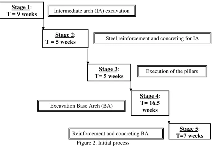
The main operations for excavation of the below ground sections, including the setting of steel frame and concreting for both the intermediate and base arches, are illustrated in Figure 2.
Figure 2. Initial process
Reinforcement and concreting BA Excavation Base Arch (BA)
Execution of the pillars Steel reinforcement and concreting for IA Intermediate arch (IA) excavation
Stage 3: T= 5 weeks Stage 2: T = 5 weeks Stage 1: T = 9 weeks Stage 4: T= 16.5 weeks Stage 5: T=7 weeks
The construction process was initially established such that the operation was to proceed sequentially in stages, the total time for execution of this phase corresponding to 42.5 weeks, obtained by adding the individual times for each stage (one week corresponding to 6 days). Excavation
The excavation face covers an area of 280 m2. This first involves, the excavation of the upper half section having a height varying from 6 to 8 m. Thereafter, the excavation of the lower half-section was carried out. These works were then followed by the installation of a support system using steel ribs and finally, the pouring of concrete to cover the entire excavation face. One repetition is carried out every two days over 25 weeks of the excavation phase, the number of cycles being 75 and each cycle corresponding to a excavation length of 75 m, as given in Table 1.
Table 1. Excavation time
Operation Length of excavation
Number of rotations
Rotation
duration Planned time
Excavation
phase 75 m 75 rotations 2 days
150 days (25 weeks)
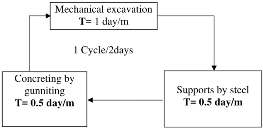
The excavation is a cyclic operation and each cycle is composed of three steps, as illustrated in Figure 3: (i) mechanical excavation; (ii) installation of steel support elements, and; (iii) placement of gunnite. The total duration of one cycle is two days.
Mechanical excavation T= 1 day/m 1 Cycle/2days Supports by steel T= 0.5 day/m Concreting by gunniting T= 0.5 day/m
Figure 3. Excavation operation Placing reinforcement steel and concreting operations
The main stages for these operations are represented in the flowchart given in Figure 4. The time given for removing the formwork is 2 days.
Concrete covering Setting of the framwork
Setting of the steel
Setting of the scaffolding
Figure 4. Stages of steel reinforcement and concrete covering operation.
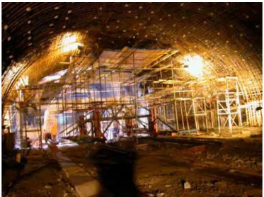
After scaffolding is set up (Figure 5), reinforcing steel together with the formwork are installed in the arch; thereafter the concreting operation can start. The hardness of the rock, inflow of water, and presence of underground services (i.e. electrical cables, gas pipes, and building foundations) were the main difficulties encountered during construction. Indeed, the rate of construction was 0.8 m/day as compared to the 1.0 m/day that was initially estimated; this generated a delay of 2.5 weeks for the excavation phase alone. In addition, a delay of 2 weeks resulted from water flowing into the gallery and another 3 weeks due to problems related to underground services. Hence, a total delay of 7.5 weeks was recorded and the construction time was 50 weeks instead of the 42.5 weeks originally planned for this phase of the work.
Figure 5. A general view of the construction underway
A summary of the time allocated to both steel reinforcement and concreting, are provided in Tables 2 and 3 respectively. The steel reinforcement operation required 10 workers (divided between two stations) and an execution time of 5 weeks. The concreting operation was realized in 14 sections (each section of 5 m length) for a total duration of 7 weeks. Table 2 gives the time needed for steel installation taking into account that a team of 10 people worked 10 hours/day for 6 days/week. This team managed an average output of 30 kg/hour of steel installation.
Table 2. Time allocated to steel reinforcement operation
Task Quantity Worker output Number of
workers Planned time
Steel
Reinforcement 181.8 tones 30 kg/hour (in 2 stations) 10 (5 weeks) 30 days Table 3 presents the time needed to fabricate concrete considering that concreting is done in segments of 5 m. On the 70 m length of the station, each segment needs one day for concreting and two days for stripping the formwork. Hence, 42 days will be needed to concrete the arch.
Table 3. Time allocated to the concreting operation
Task Volume Number of sections (5 m Length) Duration of concreting of a section
Dismantling Planned time
Concreting 18900 m3 14 1 day 2 days 42 days
Optimization of the process
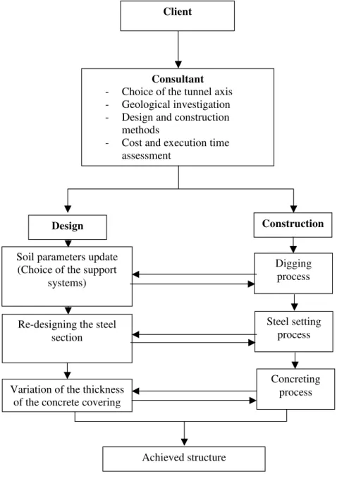
To optimize the process by considering all the difficulties encountered during excavation, the following points should be taken into account: the definition of the respective tasks within the execution phases; the study of the possibility of reducing their times; integrating a numerical simulation in real time during execution; and finally clearly defining the operations which will be executed and the exact links between them. This will result in a reduction in the number of excavation operations that are repeated, by completing an operation every 1.5 m instead of every 1 m as considered in the initial process. Note that the recommended intervals are 0.8 to 1.5 m (Bouvard, 1994; Panet, 1995). This approach is supported by numerical simulation (Figure 7).
Achieved structure
Client
Consultant
- Choice of the tunnel axis - Geological investigation - Design and construction
methods
- Cost and execution time assessment Construction Steel setting process Digging process Concreting process Design
Soil parameters update (Choice of the support
systems)
Re-designing the steel section
Variation of the thickness of the concrete covering
A better estimation of the stress distribution around the arch is obtained by considering the
analysis
ree-dimensio
is study, can be rendered to a structural problem of plane ti
methods of execution and the real condition encountered in the site.
Numerical simulation and modeling during the excavation operation
Computer tools, such as computer aided design (CAD) and solid modeling, have revolutionized the way engineers work. They can help to reduce the development time and cost of a project (De Martino, 1998). In this study, an industrial finite element
software (ANSYS) was used to model the arch excavation and the installation of steel supports and the operation of coverings by activation of the corresponding elements.
In the numerical simulation of the excavation stages of the tunnel (Attar, 2006), it is important to consider the effect of the execution in the stages of the operation. The method of “convergence-confinement” is the most appropriate method to simulate such an effect (Panet, 1995). Using this method, a th nal structural problem such as the one posed by the excavation of the arch in th
deforma on in which a stressσ =(1−λ)σ0 is applied to the internal area of the tunnel, as represented in Figure 6, where:
: Initial stress applied to the internal area of the tunnel
0
σ
λ : The degree of unconfinement corresponding to an initial value of 0 and increasing to 1 when the tunnel is not supported.
M M σ
M
σ
Initial state Intermediate state Final state
U = 0 M U = U(M λ) UM = Uinf
σ = σM 0 M ) σ0 M
λ = 0 0 <λ<1 λM =1
σ = (1-λ σ = 0
Reduction in the number of excavation operations
As mentioned earlier, the number of excavation operations could be reduced if the operation was completed every 1.5 m instead of every 1 m. Thus for a section having a 70 m length, this would yield, in total, 47 repetitions of the excavation operation instead of 70. To check the feasibility of this action, numerical simulation using the finite element method (FEM) of ana
nd and the Gneiss formation is 1 m from the top arch lysis was used to verify the execution process. The following describes the basic assumptions used in the FEM analysis.
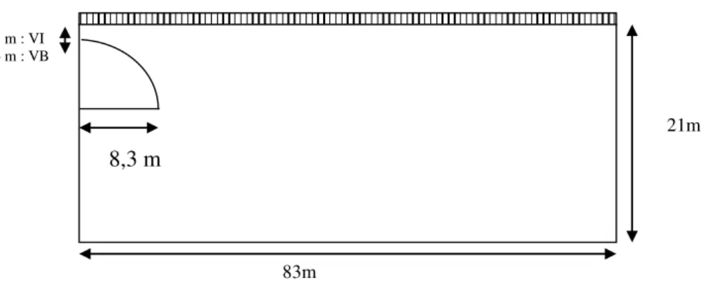
A circular tunnel is considered in a homogeneous rocky formation (Gneiss) having a perfect elasto-plastic behaviour based on Mohr Coulomb criteria (Mestat, 1995). The calculations are made assuming bi-dimensional deformation of the tunnel section, the basic configuration of which is given in Figure 8. The only external action considered is the overburden load, which also includes the load due to the buildings along the axis of the tunnel. The distance between the grou
and of 6 m from the base arch. The mechanical characteristics of the gneiss formation, steel and the concrete are given in Table 4.
83m
21m 8,3 m
1 m : VI 6 m : VB
Figure 8. FEM Model of a he longitudinal axis giving
basic dimensions and assumed loading scheme
le 4: Pr Material Young’s Modulus (E) (MPa) Poisson r Friction angle φ Cohesion (MPa) Density (
circular tunnel section along t Tab Material operties
atio (ν) t/m 3 ) Gneiss 2000 0.4 35° 1 2.7
Steel ribs HEB 260 210000 0.3 - - -
Spreading concrete 10000 0.2 - - -
Cover concrete
30000 0.2 - - - The stiffness of the support system (Bouvard, 1992) is assumed to be equal to the ombined stiffness of the two materials, i.e. KS = KS1 + KS2, where:
he bination of the two materials was considered a thin plate and according to KS=
c
Ks1: stiffness of the steel ribs,
Ks2: stiffness of concrete.
T com
Bouvard (1992), its stiffness can be determined as follow: e
R E.
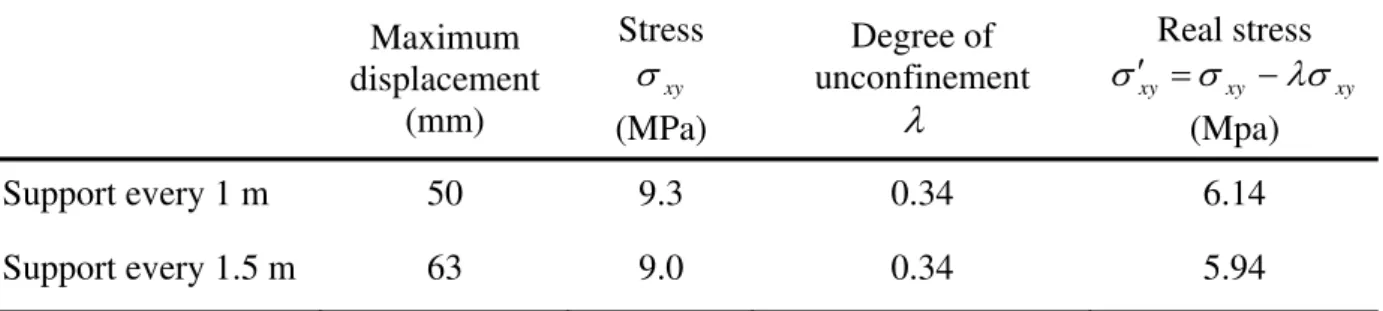
or a range interval of 1 m or 1.5 m of the support structure setting, the values of Young’s modulus are, respectively, E = 18290.7 MPa and E = 15521 MPa. The stress distribution is given in Table 5.
,
where: E: Young’s modulus; e: thickness of the plate; R: Radius of the tunnel F
Table 5. Comparison between two modes of support structure
repetitions corresponding to a total of 16.5 days within an excavation length of 70 m. However, one repetition every two days will total of 140 days within the same excavation length.
s. his allows reassessment of all stresses and their comparison to those given by the hyperstatic
action method (AF ocated 1.5 m from
the wall front, and covered with a 0.5m layer of concrete. T re given i
Tabl lac ithin covering eration
Maximum displacement (mm) Stress Real stress xy xy σxy λσ σ′ = −
The results indicate that placing a steel support every 1.5 m does not significantly affect the stresses in and the displacement of the concrete arch. However, the net result is that the time of excavation of the arch can be reduced without any undesirable structural effects. One repetition every 2.5 days will result in a total of 46.6
1
result in 70 repetitions corresponding to a
As a result, a gain of 23.5 days or 4 weeks is achieved. Recalculation of final concrete covering
Concrete cover is calculated considering the method of execution and actual site condition T
TES, 1994). The support structure consists of steel ribs l
he results a n Table 6.
e 6. Stress disp ement w op
xy σ ( Degree of unconfinement MPa)
λ
Real stress xy xy σxy λσ σ′ = − (MPa) Concrete cover 64 1.94 0.34 0.13Note that the value for the real stress is lower than the one observed in the original design in which the hyperstatic method for calculating stress was used (Cherchali, 1993). This difference is mainly due to the simplified hypotheses involved in the hyperstatic method, in comparison to the non-linear finite element method used in our case, which is considered a more realistic model.
rification of the shear stress is given as: The ve ctd cm ctd sd ≤ f +σ × f τ 2 with: b * y V u u sd = τ , b * y N u u cm = σ , c 3 / 2 cj ctd 0.7 f = *0.3f γ Maximum displacement (mm) Stress xy σ (MPa) Degree of unconfinement
λ
(Mpa) Support every 1 m 50 9.3 0.34 6.14 Support every 1.5 m 63 9.0 0.34 5.94Given the concrete strength at 28 days, fcj =28MPa, 5γc =1. ; b = 1 m, then τsd= 1.28 MPa, and τsd= 1.79 MPa, it can be seen that τsd ≤τsd.
Transversal reinforcing steel is not necessary for the arch. According to the initial calculation, the steel used for the transverse position was T12 placed every 15 cm between
ds resulting in a total of 90 tonnes of steel. The reduction in concrete thickness from
ro 0.70 m
teel and co crete, as well as a reduction in costs related to the tim
Th
given in Table 7.
Table.7. Effec cti et ne execu
e required to achi 5 m was
estimated to be 6 w ss. The impact on
the expected completion tim tallic ribs is given
in Table 8.
Tabl of decreas ber of re
To l V m Concrete placement Rate m3/hour Time of stripping th Num er of plots Expected time of execution
to 0.50 m does not significantly affect the structural behavior of the arch. The stress level in the arch is not affected by the revised spacing of the steel ribs at every 1.5 m. These two actions have positive effects on the completion dates of the project.
Effects of changes in structural configuration of the tunnel segments: Execution time and construction costs
The proposed change in the structural configuration of the tunnel lining segments relate to a revised arch thickness (reduced from 0.7 to 0.5 m) and the installation of fewer structural steel support ribs (one every 1.5 m as compared to 1 m). This has a direct effect on both material costs, in terms of reduced costs of s n
e of implementation of the work. Both of these are dealt with in turn.
e effect of the reduction in thickness of the concrete cover on the completion dates is e covering thick
t of redu on in concr ss on the tion time
ta olume 3 e Framework b Arch with a rete thickn conc ess e= 0.7 m 1200 5 2 days/plot 14 (7 weeks) 42 days
With concrete placed at a rate of 5 m3/h and given 2 days for the time to strip the framework, the overall tim
Arch with a concrete thickness
e= 0.5 m
869 5 2 days/plot 14 37 days
(6 weeks)
eve an arch having a thickness of 0. eeks compared to 7 weeks for an arch of 0.7 m thickne
e when increasing the distance between the me ing the num
e 8. Effect petitions Length to be excavated Nu of repetitions T repetition e
mber ime of a Final tim
Support every
1 m 70 m 70 2 days 140 days
Support every
Thus decreasing the thickness of concrete from 0.7 m to 0.5 m allows for a savings of 3000 €, representing 27.6% reduction of the total cost.
increasing the distance between the metallic ribs from 1 m to 1.5 m estimated at 4 weeks.
The impact of the integration of the numerical simulation in the process on the execution time is given in Table 9.
integra ion on the execution time
1540 €, presenting 34.2 % of the total cost. The impact of these two actions (reducing the thickness
d decreasin costs of the pro wn .
Table 10. Impact of numerical simulation on the construction cost at different phases.
E (€) St rt (€) (€) (€) R concrete (€) T engineering cost (€) 8
The gain in time when is
Table 9. Impact of tion of numerical simulat
The decrease in the number of repetitions from 70 to 46.6 allows for a savings of 4 re
an g the number of repetition) on the ject are sho in Table 10
xcavation eel suppo Labour Material einforced otal Civil
Without integration of numerical simulation 4116000 121160 36000 118000 300000 4691160 With integration of numerical 4116000 79620 30000 96000 217000 4538620 simulation Gain (%) 0% 34.2% 16.6% 18.6% 27.6% 3.25%
The integration of numerical tools in the execution process have shown that design parameters can be adjusted while the execution of the structure is in progress, and could generate a gain in both execution time and cost. This procedure should be used in a systematic way in underground construction (especially in urban sites) where the uncertainties could be The numerical analysis carried out previously was based on the Hyperstatic
Time reduction
Action Aim of the integration of
numerical simulation
Re er
excavation based on the setting of the support
23.5 days (4 weeks) duction in the numb
of repetitions during the simulation to validate the solution Integration of numerical system each at 1.5 m. Adjustment of the Integration of the numerical solicitations within the
covering simulation to validate the decrease in thickness of the covering concrete from 0.7 m to 0.5 m
6 days (1 week)
very diverse.
method, based on more simplified hypothesis, generating an overestimation of the stress around the cavity. This design has been improved considering the finite element method that is more realistic and represents in a better way the real behavior of the structure.
Conclusion
Delay in construction time frame is a big issue for the local construction enterprises in Algeria. Many problems can arise during the execution of underground structure projects and can have a considerable effect on the project completion time. These problems are not often tak
cavation method and hence reducing the completion times. A gain of four wee
ods can be quite valuable in large, omplex construction projects. Integrating numerical tools in the execution process and
wn to be efficient in the “Khelifa Boukhalfa” metro station. However, ient in the construction industry at large.
ements
technical input.
Refere
Anumb Design-Build
Anumb 2000),
Attar, A., Pecora, L., DiRaddo, R., Bhuiyan, N., Thomson, V. (2000), ‘Model-Based Attar, A
Séminaire international NORMATICA,
Ben M 02), ‘Vitesse et performance
chnique.
Bobrof e projet dans la construction’, Presses de l'École Nationale
des Ponts et Chaussées’, Paris.
en into consideration when assessing and planning the execution times and as a result, considerable delays take place. Using the concept of concurrent engineering by overlapping different activities involved in a construction project and making use of computer-aided tools allow for the consideration of the risks which can face such a project.
In the underground station case study presented in this paper, a sequential process was mapped and initially planned to be executed in 42.5 weeks. The hardness of the rock, the inflow of water and the risks to different services and to the constructions above the tunnel and the environmental impact (vibration and sounds) delayed the work by 7.5 weeks. The integration of a simulation in the process and the interaction of different stages have resulted in modifying the ex
ks for the excavation, two weeks for setting the steel reinforcement, and three weeks for the concreting operation of the arch were obtained. All these have reduced the time of realization by a rate of 18% with a 20% cost reduction on steel frame support and a total cost reduction of 3%.
The study demonstrates that the application of CE meth c
overlapping have sho
this process should be adopted by the major local construction in Algeria, as CE has been shown to be effic
Acknowledg
Authors would like to thank Dr M. Lacasse, Senior Researcher at NRC/IRC Canada for his
nces
A.F.T.E.S Groupe de travail N°7 (1994), ‘Tunnels et Ouvrages Souterrains.’ n° 123 Mai/Juin, 1994.
Al-Ashaab, A. and Molina, A. (1999), ‘Concurrent Engineering Framework: A Mexican Perspective’, CERA ’99, Bath, UK.
a, C.J. and Evbuomwan, N.F.O. (1997), ‘Concurrent Engineering in Projects’, Construction Management and Economics, 15(3), pp.271-281.
a, C.J., Baldwin, A.N., Bouchlaghem, D., Prasad, B., Cutting-Decelle, A.F. (
‘Integrating concurrent engineering concepts in a steelwork construction project’, Concurrent Engineering Research and Applications, 8(3), pp. 199-212.
technique for the Reduction of part development times’, ANTEC, Orlando, FL.
., Boudjakdji, M.A, Bhuiyan, N. (2006), ‘Contribution à l’optimisation des délais de réalisation des ouvrages souterrains’,
Tlemcen, Algeria.
ahmoud, S., Jouini, G., Garel, C., Midler, C. (20
économique des projets : le cas des projets à coûts contrôlés’, PESOR -Université Paris -Sud et CRG -Ecole Polyte
Blackburn, J.D. (1991), ‘Time-based competition: The next battleground in American manufacturing.’, Business One Irwin, Homewood, IL.
Bogus, S.M., Molenaar, K.R., Diekmann, J.E. (2005), ‘Concurrent engineering approach to reducing design delivery time’, Journal of Construction Engineering and Management,
Boudja ion du temps de réalisation des ouvrages
Bouvar PC, Paris, France. eliverable 3-benefits De la . Distributed Object-Eldin, 123(3), pp.354–362. an Journal of
Fulvio, nology: Applications and Design
Hoffma ngineering.’ Annual Reliability and
Hudson
Karlsso A.S., Thompson, B.P. (2008), ‘Best practices
Katranuschkov, P., Scherer, R.J., Turk, Z. (2001), ’Intelligent services and tools for
nal of Love, P
urrent Engineering: Research and Applications, June 5(2), pp.155-162.
tion, 131(11), pp. 1179-1185.
kdji, M.A. (2007), ‘Contribution à l’optimisat
souterrains’, Master’s thesis, University of Blida, Algeria.
d, A., Colombet, G., Esteulle F. (1992), Ouvrages souterrains: Conception Réalisation, Entretien, 2ème Edition, EN
Carter, C., Thorpe, A., and Baldwin, A. (1999), ‘ISoCCCrates d
assessment.’ Dept. of Civil and Building Engineering, Loughborough Univ., Leicestershire, England.
Cherchali, C. (1993), “Tunnel”, Volumes 1 to 5, OPU, Algiers, Algeria.
Garza, J.M., Alcantara, P., Jr., Kapoor, M., and Ramesh, P. S. (1994), ‘Value of concurrent engineering for A/E/C industry’, J. Manage. Eng., 10(3), pp. 46–55
De Martino, T., Falcidieno, B., Hassinger, S. (1998), ‘Design and Engineering Process Integration through a Multiple View Intermediate Modeller in a
Oriented System Environment’, Computer Aided Design, 30(6), pp. 437-452.
N.N. (1997), ‘Concurrent engineering: a schedule reduction tool’, Journal of Construction Engineering and Management,
Eversheim, W., Bochtler ,W., Grassler, R., Kolscheid,W. (1997), ‘Simultaneous Engineering Approach to an Integrated Design and Process Planning’, Europe
Operational Research, 100(2), pp. 327-337.
T., Armando, M., Vanni, D., (2005) ‘Pretunnel Tech
Methods’, Geotechnical and Geological Journal, Vol. 23, pp. 487-518, n, D.R. (1998), ‘An Overview of Concurrent E
Maintainability Symposium, CA, pp. 1-7, Jan 1998.
, J.A. and Harrison, J.P. (2000), ‘Engineering Rock Mechanics: An Introduction to the Principles’, Elsevier Science Ltd., August 2000.
n, M., Lakka, A., Sulankivi, K., Hanna,
for integrating the concurrent engineering environment into multipartner project management’, Journal of Construction Engineering and Management, 134(4), pp. 289-299.
Karoui, S., Attar, A., Boudjakdji, M.A. (2006), ‘Contribution à l’Amélioration de la Gestion des Chantiers par l'Intégration des Systèmes de Contrôle: Cas du Métro d'Alger.’ Séminaire international NORMATICA, Tlemcen, Algeria.
concurrent engineering - An approach towards the next generation of collaboration platforms’, Electronic Journal of Information Technology in Construction, 6, pp. 111-128.
Lee, S., Peña-Mora, F., Park, M. (2006), ‘Web-enabled system dynamics model for error and change management on concurrent design and construction projects’, Jour
Computing in Civil Engineering, 20 (4), pp. 290-300.
. and Gunasekan, A., (1997), ‘Concurrent Engineering in the Construction Industry’, In: Conc
Malcurat, O. (1998), ‘Modélisation d’un environnement logiciel d’assistance au travail collaboratif dans le secteur de l’architecture et du BTP’, Projet de recherche CRAI, France.
Mangini, M. and Sparacello, H.M. (1999), ‘A concurrent engineering approach to geotechnical design and construction’, Concurrent Engineering in Construc Challenges for the new millennium, CIB Publication 236.
Mesquita, M. J. M., Melhado, S. B. (2002), ‘Concurrent Engineering in Construction: Studies of brief-design integration’, Proceedings IGLC-10, Aug. 2002, Gramado, Brazil. , P. (1993), ‘Lois de comportement des géoma
Mestat tériaux et modélisation par la méthode
Midler, C., Jouini, S., (1996), ‘Ingénierie concourante dans le bâtiment : synthèse des travaux Panet, M. (1995), ‘Calcul des tunnels par la méthode convergence - confinement’, Presses de Park,
model-based project management’, Syst. Dyn. Rev.,
Peña-M esign/build
ment, 127(1), pp. 1-17.
Prasad, g fundamentals’, Editions Prentice Hall PTR, New
Songer
sis’, Journal of Construction Engineering and Storer,
uction, Challenges for the new
Winner 988), ‘The Role of
Concurrent Engineering in Weapon Systems Acquisition’, Institute for Defense Analysis, IDA Report R-338, Alexandria, VA, USA.
Zeidan, A. (2000). ‘Démarche d’estimation des délais de réalisation d’un tunnel en site urbain.’, Thèse de doctorat, Université Marne La Vallée, France.
des éléments fins’, LCPC, groupe de travail 52.
du GREMAP (Groupe de Réflexion sur le Management de Projet).’ Plan Construction et Architecture, Recherche n°75, 230 p., Paris.
l’ENPC, Paris, France.
M. and Peña-Mora, F., (2003), ‘Dynamic change management for construction: Introducing change cycle into
19(3), pp. 213–242.
ora, F., Li, M. (2001), ‘Dynamic planning and control methodology for d
fast-track construction projects’, Journal of Construction Engineering and Manage
Pot, P. (2005), ‘Optimisation des formes d'organisation dans l'industrie de la construction’, Thèse de Doctorat, Ecole Polytechnique Fédérale, Lausanne, Switzerland.
B. (1996), ‘Concurrent engineerin Jersey.
, A.D., Diekmann, J., Hendrickson, W., and Flushing, D. (2000), ‘Situational reengineering: Case study analy
Management,126(3), pp.185-190.
G., and Masat, J. (1999), ‘Time compression Construction process Supported by Appropriate IT’, Concurrent Engineering in Constr
millennium, CIB Publication 236.